 Hongtao Zhu
 Xiaoting Rui
 Fufeng Yang
95% of researchers rate our articles as excellent or good
Learn more about the work of our research integrity team to safeguard the quality of each article we publish.
Find out more
ORIGINAL RESEARCH article
Front. Mater. , 23 November 2020
Sec. Smart Materials
Volume 7 - 2020 | https://doi.org/10.3389/fmats.2020.591283
This article is part of the Research Topic Hysteresis Characterization and Control of Electrorheological and Magnetorheological Materials View all 14 articles
A cab seat suspension with a magneto-rheological (MR) fluid damper is introduced in this paper. A unified-format model for the MR damper is proposed to describe the dynamic characteristics of the MR damper. Also, a simple force-inverse model and a viscous damping tracking model are used for the coil current solution. A digital integrator and an extended Kalman filter are respectively adopted to obtain the vibration velocity of the chair frame and the relative motion velocity of the MR damper piston. A new skyhook control base with viscous damping tracking is applied to the semi-active seat suspension. In the simulation, compared with passive seat suspension under different displacement excitation (2, 4, 6, 8 Hz-sine, and random), the acceleration root mean square of the seat suspension with the MR damper is reduced by 52.2%, 32.2%, 41.3%, 50.8%, and 34.6%, respectively. In the experiment, the acceleration root mean square is reduced by 11.2%, 41.2%, 45.8%, and 31.5%, respectively under different displacement excitation (2, 4, 6, and 8 Hz-sine).
Many drivers suffer from occupational diseases, including stomach disease, heart disease, and anxiety disorder. Part of those diseases are caused by the vibration of a cab. In recent years, the application of cabs has increased, so it has become necessary to reduce the vibration of cab seats by adopting some additional controllable components, of which the magneto-rheological (MR) damper is a superior candidate. An MR damper has been applied to many aspects of engineering (Choi et al., 2016), because of its advantageous features including low-power consumption, force controllability, and rapid response. The MR damper mainly consists of MR fluid which is a designable and controllable smart material whose apparent yield strength can be changed sharply within milliseconds, by the supply of an external magnet, from a free-flowing viscous liquid to a semi-solid one (Rabinow, 1951).
The nonlinear dynamic characteristics of the MR damper limit its application in engineering. In recent years, scholars have completed an extensive amount of research on the dynamic characteristics of MR dampers. Among this research, the Bingham model (Nishiyama et al., 2002; Sun et al., 2010; Fusi et al., 2014) and the Bouc-Wen model (Spencer et al., 1997; Ikhouane and Rodellar, 2005; Bahar et al., 2009; Rodríguez et al., 2009) are commonly used in applications. The Dahl model, which is used to describe solid friction (Dahl, 1976), has also been used by some scholars to describe the hysteretic characteristics of the MR damper (Spencer et al., 1997; Ikhouane and Rodellar, 2005; Bahar et al., 2009; Rodríguez et al., 2009). Neural networks models have also been applied in the modeling of an MR damper. However, the neural network lacks the necessary physical meaning when describing the hysteresis model of the magneto-rheological damper. In most engineering applications of magneto-rheological dampers, the desired damping force needs to be converted into electric current. Therefore, an inverse model of magneto-rheological dampers is essential. Tsang et al. (2006) gives a simplified dynamic inverse model of an MR damper based on the Bingham model and the Bouc-Wen model. Also, neural network models have been widely used in dynamic inverse models (Xia, 2003; Karamodin et al., 2007; Gao and Wang, 2008; Bhowmik et al., 2010).
In semi-active seat suspension vibration isolation control, the skyhook control is still one of the main methods of the engineering application (Hatwalane, 2016). Lee and Jeon (2002) uses a 2-state skyhook control (on-off skyhook control) for seat suspension with an MR damper. Choi et al. put MR dampers into commercial seats applying the skyhook control. In Choi and Han (2007), a no-jerk skyhook control was proposed to reduce acceleration jerk. A sliding-mode control based on a human body model was used in MR damper seats in Choi and Han (2007), but it is difficult to realize in engineering. The H∞ control was applied to the vibration isolation control of the seat suspension with an MR damper by Yao et al. (2013). Bai et al. (2016) and Bai et al. (2017) put a rotary MR damper into the seat suspension for both longitudinal and vertical vibration attenuation. A variety of advanced controllers were designed for seat suspension with MR dampers by Phu et al. (2017), Xuan et al. (2017), and Phu et al. (2019).
In this paper, the MR damper is applied into commercial air-spring cab seats. The structure of the seat suspension used in the paper is shown in Figure 1. The main contributions in this paper are given as follow: 1) a unified-format model for an MR damper combining the Bingham model and the Bouc-Wen model is proposed; 2) a viscous damping tracking model based on the Bingham model is applied into a skyhook control; 3) an improved on-off control is proposed for comparison; and 4) a low-cost 3-sensor semi-active seat structure is put forward, in which the digital integrator and an extended Kalman filter are adopted for signal processing.
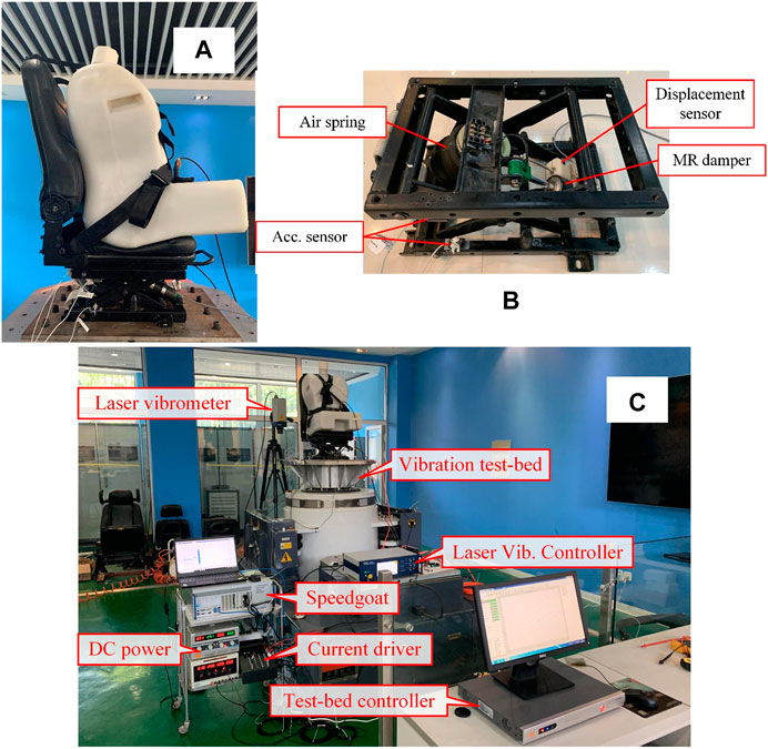
FIGURE 1. The structure of the scissors-linkage seat suspension and experiment setup: (A) seat photo; (B) the structure of the scissors-linkage seat suspension; (C) the experiment setup.
The paper is organized as follows: System Configuration and Modeling mainly introduces the system structure and system modeling; a new skyhook control is introduced in Vibration Isolation Control; the simulation results of sine displacement excitation and random displacement excitation are discussed in System Simulation; the signal processing of the sensor is given in Signal Processing; and the experimental results are shown in Experiment.
The structure of a scissors seat in this paper is given in Figure 1B. From Figure 1B, we can see that a scissors seat is mainly composed of a shear bar, an air spring, and an MR damper. The shear bar is mainly used to keep the seat mechanism stable, and the air spring is used to provide seat support rigidity. The MEMS (Micro-Electro-Mechanical System) acceleration sensor is used to measure the acceleration of the chair frame and the base, and MEMS has the advantages of long life, small size, and low price. The resistance ruler, whose accuracy can reach 0.01 mm, is used to measure the stroke of the MR damper. Also, compared to other types of displacement sensors, the resistance ruler is cheap and suitable for the market.
A coil current driver is used to provide a controlled current for the MR damper. The current driver used in this paper is composed of a power circuit, a microcontroller (MCU), a bootstrap circuit, and a H-bridge drive circuit. The microcontroller selects STM32F401 of ST Co., and its main frequency can reach up to 84 MHz. Figure 2A shows the PCB board of the current driver designed in this paper.
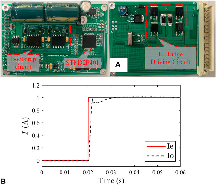
FIGURE 2. Current driver: (A) PCB board; (B) step response.
In simulation, the current driver of the MR damper is regarded as a typical 1-st system, and its transfer function is given as follows:
where,
In order to facilitate the discussion, an unified-format model is established for an MR damper.
In Eq. 2,
When the model takes the Bingham model (Zhu et al., 2019),
where,
When the model takes the normalized Bouc-Wen model (Zhu et al., 2019) and there is
In Eq. 4,
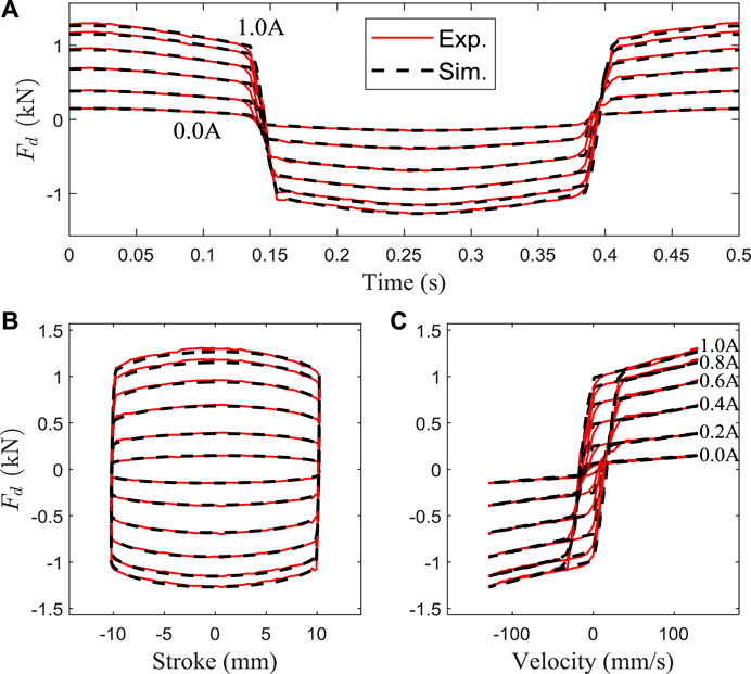
FIGURE 3. Comparison between the predicted and experimental data (normalized Bouc-Wen model): (A) the damping force vs. time; (B) the damping force vs. stroke; (C) the damping force vs. velocity.
The exponential function is used in the parameter fitting and the fitting results are shown Table 1.
where,

TABLE 1. Fitting results of MR damper parameters.
The fit curves of parameters (
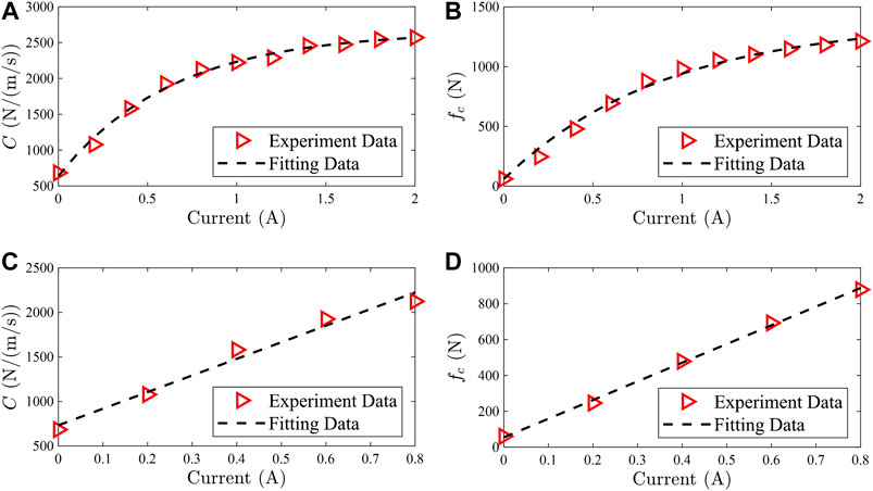
FIGURE 4. Parameter fit curve: (A) nonlinear fitting of parameter
When the current is small, the parameters (
The expected force of the MR damper is noted as
where,
At the same time, under the condition of a small current, the equivalent viscous damping coefficient
When the model takes the Bingham model,
where,
Due to the energy consumption characteristics of the MR damper, it is impossible to generate the active force, so the expected force of the MR damper is the viscous damping force, which is:
where,
Also, according to Eqs 8 and 9, the expected current form of the MR damper is:
When the model takes the Bingham model,
The Bouc-Wen model is used as the accurate model of the MR damper, and the viscous damping tracking simulation is carried out under different control frequencies (20, 50, and 100 Hz). The simulation results are shown in Figure 5, and when the current control frequency is small, the
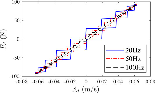
FIGURE 5. Simulation results of viscous damper tracking.
The schematic diagram of the seat suspension model is shown in Figure 6. In the schematic diagram, the seat suspension system is regarded as a 2-DOFs system.
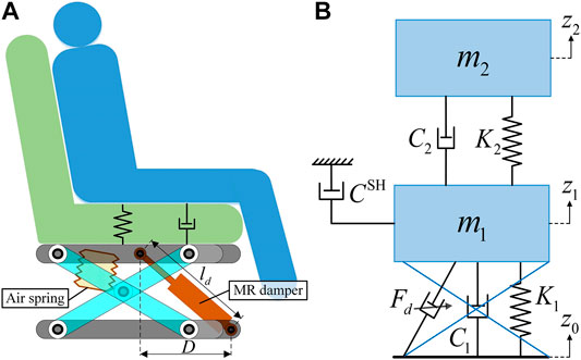
FIGURE 6. The schematic diagram of the seat system: (A) the structure of the scissors-linkage seat; (B) the schematic diagram of the skyhook control for the seat suspension.
According to the Newton formula, the dynamic equation of the seat suspension model is established as follows:
where
In Eq. 18,
The parameter value of the seat suspension system for the simulation is given in Table 2.
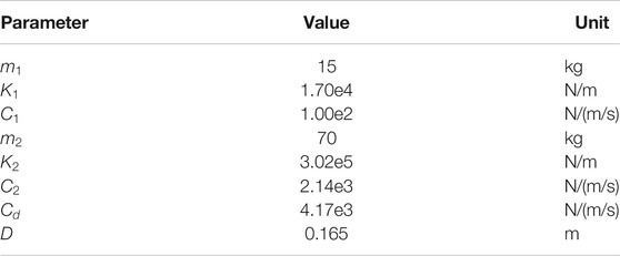
TABLE 2. Parameter value of the seat suspension system.
In the above table,
Skyhook control (SH) is one of the most widely used control strategies in suspension control. As shown in Figure 6B, a hypothetical ceiling damper is placed between the seat frame and the ideal ceiling, and its damping coefficient is
Considering the nonlinear dynamic characteristics of the MR damper, the expected current of the MR under continuous SH control is:
where,
When the skyhook damping coefficient
In order to avoid frequently switching the current output, the above formula is improved as follows:
Where, εa > 0 is the absolute velocity threshold constant; εr > 0 is the relative velocity threshold constant is the form of force-inverse model is given in Eq. (10). And, the larger the values of εa and εr, the smoother the current output.
Since
where,
According to Eq. 20, there is:
In Eq. 26,
Since the value of
where,
The value range of
Considering that the value of
Bringing the value range of Eq. 28 into Eq. 29, there is:
According to the seat geometry, the desired damping coefficient
According to Eq. 16, the expected current of the MR damper can be obtained as follows:
If an unidirectional current is applied to the iron core of the MR damper for a long time, the iron core will have residual magnetism. In order to avoid residual magnetism of the iron core, the current direction is continuously changed during current control in Eq. 33.
According to ISO2631–1, the sensitive frequency range of the human body is about 2–8 Hz. Therefore, sinusoidal base displacement (2, 4, 6, 8 Hz) is adopted to the seat displacement excitation. The simulation results of the sinusoidal displacement excitation at different frequencies is shown in Figure 7. In Figure 7, “HD” represents the passive hydraulic damper; “SH” represents the skyhook control; “On-Off” represents the on-off control; and “New-SH′ represents the skyhook control based on viscous damping tracking.
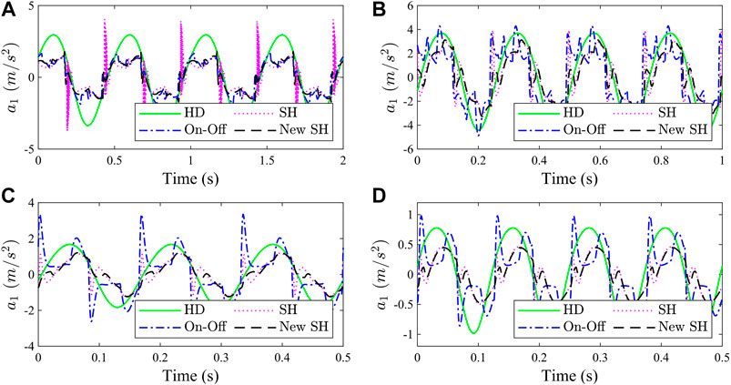
FIGURE 7. Simulation results of sinusoidal displacement excitation: (A) 2 Hz, (B) 4 Hz, (C) 6 Hz, and (D) 8 Hz.
Compared with seat suspension with passive hydraulic dampers, the acceleration of the seat suspension with the MR damper, is significantly reduced under different-frequency displacement base excitation. Compared with passive suspension, under 2 Hz-sinusoidal displacement excitation, the acceleration RMS of the MR damper seat suspension with different control methods (SH, On-Off, and New-SH) decreased by 52.0%, 56.9%, and 52.2%, respectively. Under 4 Hz-sinusoidal displacement excitation, it decreased by 30.0%, 14.0%, and 32.2%. Under 6 Hz-sinusoidal displacement excitation, it decreased by 38.6%, 5.2%, and 41.3%. Under 8 Hz-sinusoidal displacement excitation, it decreased by 48.2%, 22.6%, and 50.8%. The following conclusions can be drawn from Figure 7: 1) the acceleration RMS reduction effect of “SH” and “New-SH” is similar, but the acceleration peak of “New-SH” is smaller; 2) the improved on-off control in this paper performs better in the low frequency (near natural frequency), but poorly in the high frequency region.
The expected current of the MR damper under sinusoidal displacement excitation is shown in Figure 8. Compared with the traditional skyhook control and on-off control, the expected current of the skyhook control based on viscous damper tracking is smoother. This is because the SH control proposed in this paper converts the active force into the desired damping coefficient of the MR damper, and limits the value range of the desired viscosity coefficient within a reasonable range.
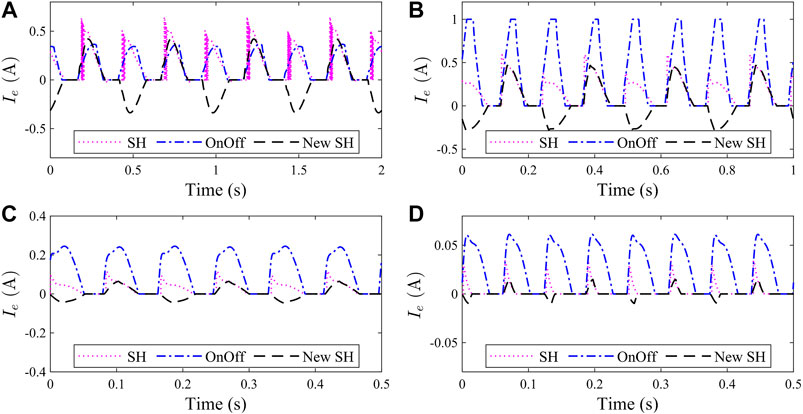
FIGURE 8. Expected current of MR damper: (A) 2 Hz, (B) 4 Hz, (C) 6 Hz, and (D) 8 Hz.
According to ISO-8608, the displacement PSD (power spectrum value) of road space surface is:
In Eq. 34,
The vehicle speed is recorded as
Then the displacement PSD of the road time unevenness is:
Using the sine superposition method, it is not difficult to get the time unevenness of the road surface
where,
The seat displacement excitation
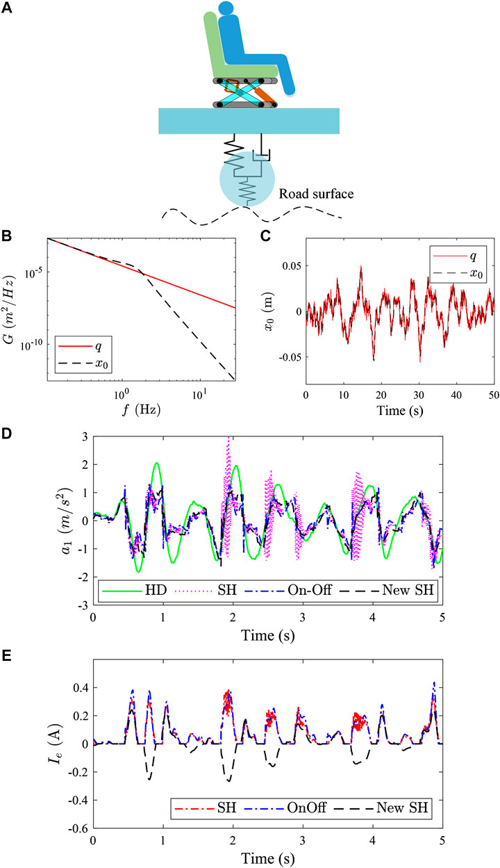
FIGURE 9. Random input for seat suspension (
The filtering effect of the vehicle body on the road excitation is regarded as a typical second-order filter, and its transfer function is:
In Eq. 38,
The displacement PSD of z0 is noted as
when the vehicle speed is 10 m/s and the road type is C. The displacement PSD curve and time-domain curve is shown in Figures 9B,C.
The seat suspension simulation results under the above displacement excitation is give in Figure 9D. It is not difficult to conclude from Figure 9D that, compared with the traditional passive seat suspension, the vibration isolation effect of the seat suspension using the MR damper is significantly improved. Under the random displacement excitation in Figure 9C, the acceleration RMS of the seat frame is reduced by 28.0%, 38.9%, and 34.6%, respectively for those three control strategies (SH, On-Off, and New-SH).
Figure 10A shows the block diagram of the signal processing in this paper. The seat frame acceleration signal passes through the low-pass filter (LP), high-pass filter (HP), and digital integrator in sequence to obtain the vibration velocity of the seat frame. The relative velocity of the piston of the MR damper is obtained through the extended Kalman filter (EKF).
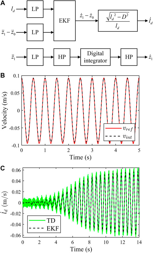
FIGURE 10. The signal processing diagram and results: (A) the signal processing diagram; (B) acceleration signal integration results; and (C) EKF signal fusion results.
The transfer function of the first-order high-pass filter is given as follows:
where,
Through bilinear transformation, it is not difficult to get the discrete transfer function of the high-pass filter:
In Eq. 41,
In signal integration, the following form of the digital integrator is used:
The vibration velocity signal measured by the laser vibrometer is used as a reference signal, and the acceleration signal integration experiment results are shown in Figure 10B. Figure 10B,
The state vector of EKF is noted as
The constant acceleration (CA) model is established and
In Eq. 44,
The steps of the EKF algorithm are given in the following equation:
In Eq. 49,
where,
The experimental results of the damper piston relative velocity is given in Figure 10C. In Figure 10C, “TD” represents the result of the tracking differentiator (Wang et al., 2003) and “EKF” represents the result obtained by EKF. The experimental results show that the noise of the damper piston relative speed is smaller and the signal has a good tracking performance. Figure 10C shows that, adopting EKF, the relative velocity of the damper piston has smaller noise and a good tracking performance.
As it is shown in Figure 1C, the experimental setup is mainly composed of DC power, a real-time control system (Speedgoat IO135 with MATLAB/Simulink, Switzerland), a laser Doppler vibrometer (LDV, type: OFV-505/OFV-5000, Polytec, Germany), a vibration test-bed, a scissors-seat with an MR damper, and a coil current driver. As a rapid control prototype, speedgoat is used to collect and store sensor signals, and output the desired current signal of the MR damper. The LDV is used to measure the vibration velocity of the chair surface as a velocity reference to verify the accuracy of the acceleration signal integration. The vibration test-bed is adopted to provide displacement excitation for the seat suspension. The current driver is used to provide controlled current for the coil of the MR damper.
The experimental results of sinusoidal displacement excitation are shown in Figure 11. Compared with passive suspension, under 2 Hz-sinusoidal displacement excitation, the acceleration RMS of the MR damper seat suspension with different control methods (SH, On-Off, and New-SH) decreased by 11.4%, 12.0%, and 11.2%, respectively. Under 4 Hz-sinusoidal displacement excitation, it decreased by 38.4%, −4.9%, and 41.2%. Under 6 Hz-sinusoidal displacement excitation, it decreased by 43.6%, 8.6%, and 45.8%. Under 8 Hz-sinusoidal displacement excitation, it decreased by 31.2%, 30.1%, and 31.5%.

FIGURE 11. Experimental results of sinusoidal displacement excitation: (A) 2 Hz, (B) 4 Hz, (C) 6 Hz, and (D) 8 Hz
The expected current of the different control strategies under sine displacement excitation are shown in Figure 12. Experimental results show that, compared to traditional skyhook control and on-off skyhook control, the desired current of new skyhook method based on the viscous damping tracking proposed in this paper is relatively smoother and smaller, which can reduce system power consumption to some extent.
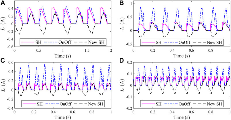
FIGURE 12. Expected current of the MR damper: (A) 2 Hz, (B) 4 Hz, (C) 6 Hz, and (D) 8 Hz
The 2–40 Hz sine wave sweep excitation put into the seat suspension, and the acceleration transmission rate in frequency-domain are defined as follows:
where,
Figure 13 shows the results of the 2–40 Hz frequency sweep experiment, in which “MRD-0A′ represents the MR damper with a 0 A current and “MRD-1A′ represents the MR damper with a 1A current. It can be seen from the Figure 13 that, compared with passive suspension, the seat suspension with the MR damper has good vibration isolation performance at different frequencies.
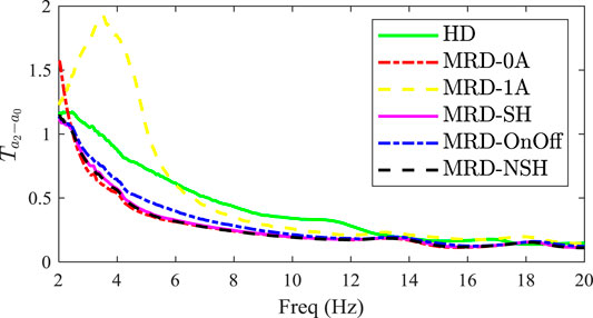
FIGURE 13. The results of the 2–40 Hz frequency sweep experiment.
In this work, a low-cost 3-sensor seat suspension structure with an MR damper was established, in which a digital integrator and an extended Kalman filter were adopted to enhance the signal quality in signal processing. A unified-format model for the MR damper and a viscous damping tracking model based on the Bingham model were proposed. Simulation results show that, compared to traditional skyhook control and on-off control, the new SH control with viscous damping tracking had a good performance in reducing acceleration jerk and smoothing the expected current output. However, in the experiment, the vibration isolation effect of “SH” and “New SH” was similar, and the difference between them was that the output current of “New SH” was small and smooth, which reduced the power consumption of the system to a certain extent.
The original contributions presented in the study are included in the article/supplementary material, further inquiries can be directed to the corresponding author/s.
As the first author of this paper, HZ have completed most of the work in this paper. XR, WZ, and JG funded this paper. FY assist to complete the experiment.
The authors declare that the research was conducted in the absence of any commercial or financial relationships that could be construed as a potential conflict of interest.
The authors wish to acknowledge the financial support of the National Natural Science Foundation of China (Grant No. 51975298), the National Natural Science Foundation of China (Grant No. 11902158), the Natural Science Foundation of Jiangsu Province, China (Grant No. BK20181301), and the Fundamental Research Funds for the Central Universities (No. 30919011240).
Bahar, A., Pozo, F., Acho, L., Rodellar, J., and Barbat, A. (2009). Parameter identification of large-scale magnetorheological dampers in a benchmark building. Comput. Struct. 88, 198–206. doi:10.1016/j.compstruc.2009.10.002
Bai, X. X., Jiang, P., Pan, H., and Qian, L. J. (2016). “Analysis and testing of an integrated semi-active seat suspension for both longitudinal and vertical vibration control,” in Active and passive smart structures and integrated systems 2016International Society for Optics and Photonics, Vol. 9799, 979921.
Bai, X.-X., Jiang, P., and Qian, L.-J. (2017). Integrated semi-active seat suspension for both longitudinal and vertical vibration isolation. J. Intell. Mater. Syst. Struct. 28(8), 1036-1049. doi:10.1177/1045389X16666179
Bhowmik, S., Høgsberg, J. B., and Weber, F. (2010). “Neural network modeling of forward and inverse behavior of rotary MR damper,” in Proceedings of NSCM-23. The 23rd Nordic seminar on computational mechanics, Stockholm, Sweden, October 21–22, 2010. Editor A Eriksson and G. Tibert (The Royal Institute of Technology), 169–172.
Choi, S.-B., and Han, Y.-M. (2007). Vibration control of electrorheological seat suspension with human-body model using sliding mode control, J. Sound Vib. 303, 391–404. doi:10.1016/j.jsv.2007.01.027.
Choi, S. B., Li, W., Yu, M., Du, H., and Do, P. X. (2016). State of the art of control schemes for smart systems featuring magneto-rheological materials. Smart Mater. Struct. 25, 043001. doi:10.1088/0964-1726/25/4/043001.
Dahl, P. R. (1976). Solid friction damping of mechanical vibrations. AIAA J. 14, 1675–1682. doi:10.2514/3.61511.
Fusi, L., Farina, A., and Rosso, F. (2014). Retrieving the Bingham model from a bi-viscous model: some explanatory remarks, Appl. Math. Lett. 27, 11–14. doi:10.1016/j.aml.2013.08.009.
Gao, M., and Wang, C. Z. (2008). Inverse modelling of MR damper based on ANFIS technique and its application. J. Vib. Shock 27(3), 140–141. doi:10.3901/CJME.2008.04.040
Hatwalane, S. (2016). “Review of driver seat suspension using MR fluid damper,” in AMET-2016 (Pune, India: MIT College of Engineering). doi:10.14741/Ijcet/22774106/Spl.4.2016.66
Ikhouane, F. A., and Rodellar, J. (2005). On the hysteretic bouc-wen model. Nonlinear Dynam. 42, 79–95. doi:10.1007/s11071-005-0070-x.
CrossRef Full Text |Karamodin, A., Kazemi, H. H., Rowhanimanesh, A., Totonchi, A., and Reza, H. (2007). Semiactive control of structures using neuro-inverse mode of MR dampers. Scientia Iranica, 16(3). doi:10.1243/09544097JRRT240
Lee, Y., and Jeon, D. (2002). A study on the vibration attenuation of a driver seat using an MR fluid damper, J. Intell. Mater. Syst. Struct. 13, 437–441. doi:10.1106/104538902028606.
Nishiyama, H., Fushimi, S., and Nakano, M. (2002). Numerical simulation of MR fluid damping characteristics using a modified Bingham model. J. Intell. Mater. Syst. Struct. 13, 647–653. doi:10.1177/1045389x02013010007.
Phu, D. X., Quoc Hung, N., and Choi, S.-B. (2017). A novel adaptive controller featuring inversely fuzzified values with application to vibration control of magneto-rheological seat suspension system. J. Vib. Contr. 24(21), 5000-5018. doi:10.1177/1077546317740479.
Phu, D. X., Hung Nguyen, Q., and Choi, S.-B. (2019). New hybrid optimal controller applied to a vibration control system subjected to severe disturbances, Mech. Syst. Signal Process. 124, 408–423. doi:10.1016/j.ymssp.2019.01.036.
Rabinow, J. (1951). The magnetic fluid clutch. J. Inst. Electr. Eng. 1952, 33–34. doi:10.1049/jiee-2.1952.0007
Rodríguez, A., Iwata, N., Ikhouane, F., and Rodellar, J. (2009). Model identification of a large-scale magnetorheological fluid damper, Smart Mater. Struct. 18, 015010. doi:10.1088/0964-1726/18/1/015010.
Spencer, B. F., Dyke, S. J., Sain, M. K., and Carlson, J. D. (1997). Phenomenological model for magnetorheological dampers, J. Eng. Mech. 123, 230–238. doi:10.1061/(asce)0733-9399(1997)123:3(230).
CrossRef Full Text |Sun, Y., Thomas, M., and Masounave, J. (2010). A quasi‐Bingham model for predicting electrorheological fluid behaviour, Multidiscip. Model. Mater. Struct. 6, 141–165. doi:10.1108/15736101011055301.
Tsang, H. H., Su, R. K. L., and Chandler, A. M. (2006). Simplified inverse dynamics models for MR fluid dampers. Eng. Struct. 28, 327–341. doi:10.1016/j.engstruct.2005.06.013.
Wang, X., Chen, Z., and Yuan, Z. (2003). Design and analysis for new discrete tracking-differentiators. Appl. Math. Chin. Univ. 18, 214–222. doi:10.1007/s11766-003-0027-0.
Xia, P.-Q. (2003). An inverse model of MR damper using optimal neural network and system identification. J. Sound Vib. 266, 1009–1023. doi:10.1016/s0022-460x(02)01408-6.
Xuan, P. D., An, J. H., and Seung-Bok, C. (2017). A novel adaptive PID controller with application to vibration control of a semi-active vehicle seat suspension. Appl. Sci. 7, 1055. doi:10.3390/app7101055
Yao, H. J., Fu, J., Yu, M., and Peng, Y. X. (2013). Semi-active control of seat suspension with MR damper. J. Phys. Conf. Ser. 412, 012054. doi:10.1088/1742-6596/412/1/012054
Keywords: magneto-rheological damper, semi-active seat suspension, skyhook control, Bingham model, Bouc-Wen model, viscous damping tracking
Citation: Zhu H, Rui X, Yang F, Zhu W and Gu J (2020) Semi-Active Scissors-Seat Suspension With Magneto-Rheological Damper. Front. Mater. 7:591283. doi: 10.3389/fmats.2020.591283
Received: 05 August 2020; Accepted: 14 September 2020;
Published: 23 November 2020.
Edited by:
Xian-Xu Bai, Hefei University of Technology, ChinaReviewed by:
Phu Xuan Do, Vietnamese-German University, VietnamCopyright © 2020 Zhu, Rui, Yang, Zhu and Gu. This is an open-access article distributed under the terms of the Creative Commons Attribution License (CC BY). The use, distribution or reproduction in other forums is permitted, provided the original author(s) and the copyright owner(s) are credited and that the original publication in this journal is cited, in accordance with accepted academic practice. No use, distribution or reproduction is permitted which does not comply with these terms.
*Correspondence: Xiaoting Rui, cnVpeHRAMTYzLm5ldA==
Disclaimer: All claims expressed in this article are solely those of the authors and do not necessarily represent those of their affiliated organizations, or those of the publisher, the editors and the reviewers. Any product that may be evaluated in this article or claim that may be made by its manufacturer is not guaranteed or endorsed by the publisher.
Research integrity at Frontiers
Learn more about the work of our research integrity team to safeguard the quality of each article we publish.