 Ruyue Song
 Anastasia Muliana
- Department Mechanical Engineering, Texas A&M University, College Station, TX, United States
This study presents a non-linear deformation analysis of a thin composite plate undergoing shape reconfigurations triggered by electric field inputs. The composite plate consists of electro-active and inactive (substrate) layers. Prescribing electric field inputs to the electro-active layer induces large curvatures in the composites, while the in-plane stretch is relatively small. This has a consequence that only shapes with zero (or nearly zero) Gaussian curvature can be attained by prescribing the electric field, which leads to snap-through shape reconfigurations in order to achieve developable surfaces. When the substrate is made of an elastic layer, the shape returns to its original planar configuration upon removal of the electric field. In order to fully or partially retain the reconfigured shape upon removing the electric field input, a substrate layer made of a shape memory polymer is considered. Shape reconfigurations and retentions of the composites having elastic substrate and shape memory substrate are simulated.
Introduction
Shape shifting or shape reconfigurable systems have the ability to reversibly change their configurations in response to external stimuli. These systems are usually found in many living organisms, e.g., opening and closing of pine cones due to moisture changes, nastic motion of plants, solar tracking sunflowers, etc. (Brown, 1916; Dawson et al., 1997; Vandenbrink et al., 2014). The main feature of the shape shifting mechanisms in biological materials is that they can undergo complex shape changes and large deformations with relatively small external stimuli. Such a feature is appealing for many engineering applications, ranging from morphing structures, actuators, soft robots, and biomedicine. Scientists have proposed numerous concepts using various materials in designing shape reconfiguration structures activated by non-mechanical stimuli. One of the common concepts is using multi-layers of materials, each with different physical properties, and upon prescribing external stimuli (thermal, chemical, electrical, etc.) the layers will experience different in-plane stretch and hence inducing shape changes (e.g., Hyer, 1982; Smela et al., 1995; Russell, 2002; Kuo et al., 2005; Stoychev et al., 2012; Ye et al., 2016).
The soft and compliant nature of polymers and elastomers makes them easily formed into various shapes. Additionally, the shape reconfigurable systems are typically formed out of thin plates, which due to their low bending and torsional rigidities allow for achieving complex three-dimensional shapes. Hence, multi-layer thin plates out of polymers or elastomers are commonly considered for shape reconfigurable systems. By integrating active polymers, such as shape memory polymers (SMPs), electro-active polymers, ionic polymers, etc., to the multi-layer systems, the complex three-dimensional shapes can be achieved by non-mechanical stimuli. Janbaz et al. (2016) used bilayers out of SMP and elastomer in forming self-rolling and self-twisting soft structures. Upon heating, the thermal responsive characteristic of the SMP leads to shape-shifting of the systems. Stoychev et al. (2012, 2013) have utilized swelling mechanisms in polymer bilayers in order to achieve various folding of bilayers. The two layers differ significantly in their swelling behaviors, i.e., hydrophobic polymer and thermo-responsive hydrogels. The slow diffusion process leads to non-uniform expansion or shrinking, and hence influences the folding paths. The geometrical aspect ratios of the bilayers, i.e., in-plane dimension and thickness of each layer, govern the folding patterns. Ma et al. (2013) discussed the use of water responsive polymer films that can generate continuous motions driven by water gradients, for potential soft robotic applications. The polymer film can lift and transport objects more than 10 times of its weight. Folding and unfolding of multi-layered polymers also find applications for encapsulation and delivery of drugs, as discussed by Fernandes and Gracias (2012). The authors presented folding and locking mechanisms in polymers by a water migration process in order to form complex polyhedral shapes. Review articles on various shape reconfiguration mechanisms and active polymers that promote self-reconfigurations can be found in Meng and Hu (2010) and Ko and Javey (2017).
Modeling and simulation of multi-layered systems subjected to non-mechanical stimuli have been a subject of interest for many decades. Timoshenko (1925) has presented a general theory of bending of a bilayer beam subjected to a uniform heating. He considered a rather slender strip out of a linear elastic material with a linear thermal expansion coefficient for each layer. Due to the slender nature of the bilayer, only the elongation/contraction along the longitudinal axis of the beam is being considered. Following this concept, several researchers have simulated bending in multi-layered beams subjected to spontaneous changes in solvent contents, electric field, or magnetic field (e.g., Crawley and De Luis, 1987; Henke et al., 2012; Sheridan et al., 2014; Muliana, 2015; Tajeddini and Muliana, 2015). Both linear and non-linear constitutive material responses have been incorporated, and various beam theories have been considered. There have been studies on modeling shape changes in multi-layered beams undergoing transient diffusion of fluid, ion, and/or heat conduction (e.g., Nemat-Nasser, 2002; Kuravi et al., 2012; Drozdov, 2016; Parthasarathy et al., 2016). Drozdov (2016) presented a constitutive model for bending of an ionic polymer membrane with thin electrode layers on its top and bottom surface due to the diffusion of ion upon prescribing electric fields. Using a micromechanics approach (Nemat-Nasser, 2002) developed a coupled electrical-chemical-mechanical model for ionic polymer composites, taking into account the effects of chemical compositions of the polymer, morphology of the electrodes, types of cations, and water hydration stage on the bending of the composites.
Theoretical and computational models have also been considered for describing shape reconfigurations in planar (two dimensional) composite sheets triggered by non-mechanical stimuli. Dimitriadis et al. (1991) presented analytical solutions of a composite plate with an elastic substrate with distributed piezoelectric patches. Xue et al. (2011) presented non-linear partial differential equations of large deformation in von Karman thin plate under magneto-elastic coupling. Alben et al. (2011) used Foppl - von-Karman plate theory to describe the edge effects in elastic bilayer folding. It is noted that the von-Karman theory can capture large bending of thin plates, but it is limited in capturing rolling of thin plates. Ye et al. (2016) used a lattice spring model in order to simulate self-rolling of 2D planar film triggered by a through thickness swelling gradient. The 2D medium is described by network of interconnected beads and each network is represented by a spring. The elasticity of the polymer sheets is incorporated through the stiffness of the springs. Swelling regions, which govern the folding shapes, are modeled by changing the length of the bond in the active networks (swelled regions). Finite element method has been used to simulate large deformation shape reconfigurable in multi-layered 2D planar surfaces activated with various stimuli (e.g., Mailen et al., 2015; Tajeddini and Muliana, 2017; Bartels et al., 2018). Bartels et al. (2018) also discussed the occurrence of corner folding (termed as dog ears) of planar surfaces instead of folding into desired cylindrical shapes, which is attributed to a slow diffusivity process. Shape reconfigurations can also be achieved through snap-through mechanisms in multi-stable layered systems (e.g., Guest and Pellegrino, 2006; Daynes et al., 2010; Chen et al., 2012; Jiang et al., 2018). Daynes et al. (2010) utilized thermal stimulus in order to achieve multiple shape changes in multi-stable laminated composite plates. Jiang et al. (2018) studied snapping of bistable pre-stressed disks comprising of electro-active polymer (EAP) layers. They determined the Gaussian curvature of the disks in order to identify the geometrical shapes that can be achieved by the snap-through mechanism via prescribing electric field to the EAP.
This study presents modeling and simulation of thin bilayer composites undergoing large deformation shape reconfigurations prescribed by a non-mechanical stimulus, e.g., electric field. The composites comprise of two layers (one active and one inactive layers). The electric field input causes expansion/contraction in the active layer. The simulation is also applicable when spontaneous thermal or moisture stimulus is considered. The thin layered nature allows us to ignore the transverse shear effect. As will be shown later, the axial stretching from prescribing non-mechanical stimuli is relatively small, and hence does not contribute significantly to the shape changes. In the thin layered system, axially stretching the active layer results in large through the thickness deformation gradients, and hence the shape changes are governed by large rotations. The spontaneous shape reconfigurations that can be achieved have the Gaussian curvature zero (or nearly zero). This study also considers shape shifting behaviors due to snap-through responses of the bilayer upon prescribing relatively large electric field. In most shape shifting systems that are activated by electric field, the shape returns to its original configuration upon removal of the electric field. By constructing a bilayer system comprising of an electro-active layer bonded with a shape memory layer, allows for retaining (either fully or partially) the shapes upon removal of the electric field. The outline of the paper is as follows. Section Mathematical Formulation of Thin-Multi-layered Active Composites presents the mathematical model of bilayer composites activated by a spontaneous application of external fields. Section Modeling Bilayers with Electro-Active and Shape Memory Layers discusses bilayer models comprising of electro-active and shape memory polymers. The analyses of the two systems are discussed in section Results. The summary of this study is given in section Summary.
Mathematical Formulation of Thin-Multi-Layered Active Composites
Typical thin multi-layered active composites comprise of three or two layers, see illustrations in Figure 1. In the three-layer system, active materials are usually placed on the top and bottom layers while the middle substrate is made of an inactive material. Prescribing a non-mechanical stimulus, e.g., electric or magnetic field, to the active layer(s), induces in-plane stretching or contraction. Different in-plane stretching/contraction in these two active layers generates axial stretching and curvature in the thin composite. The inactive substrate is added to increase the distance between the two active layers, and hence increasing the corresponding moment. However, adding an inactive substrate can also increase the overall rigidity of the composite, making the composite less compliant. An alternative arrangement is to consider bilayer systems, comprising of active and inactive layers or two active layers. This study considers attaining three-dimensional shape reconfigurations (or folding) out of a planar system, and hence it is necessary for the different layers in the multi-layer systems to have different in-plane stretching/contraction upon prescribing external stimuli. As will be discussed later, in a thin composite plate the out of plane deformations due to prescribing non-mechanical stimuli are governed by large rotations and the magnitude of the axial stretching is usually small (negligible with respect to the overall rotations). For this reason, it is convenient to map the neutral surface, which does not experience in-plane stretching and contraction, in order achieve shape reconfiguration. Therefore, the shape reconfigurations that can be achieved spontaneously by prescribing the non-mechanical stimuli are associated with zero Gaussian curvature. The corresponding surfaces are classified as developable surfaces. A brief discussion on the Gaussian curvature and developable surface is given in Appendix A (Supplementary Material).
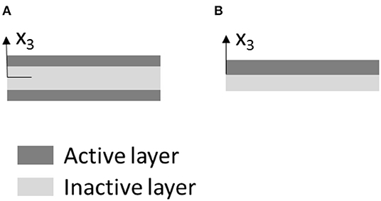
Figure 1. Multi-layered active composites of different arrangements: (A) sandwich system and (B) bilayer of active and inactive materials.
In this section a spontaneous application of an electric field input in the thin bilayer composite is considered. Other types of stimuli, i.e., uniform temperature or moisture change, can also be considered due to the similar shape reconfiguration mechanisms. Prescribing an electric potential difference along the thickness of the active layer generates a uniform electric field in the active layer and hence a uniform in-plane stretching/contraction along the layer. Out of plane deformations in a bilayer composite induced by a spontaneous temperature change can be mathematically modeled. Polymers generally have low thermal conductivity; thus, practically it might not be possible to achieve spontaneous shape changes by a thermal stimulus. In such situation, a transient diffusion process (thermal field various in space and time) is required in simulating shape reconfigurations in thin polymer bilayers. The transient process is also applicable for bilayers undergoing diffusion of fluid (e.g., experimental studies by Stoychev et al., 2012, 2013). Different shape reconfigurations can occur in the same polymers bilayers when subjected to spontaneous and transient thermal stimuli. Likewise, the transient process can be simulated for the electro-mechanical responses in composites by prescribing electric field that varies in time and space; however, this process might not be practical.
Consider a bilayer thin composite plate comprising of active and inactive layers (Figure 1B), and the thicknesses of the active and inactive layers are ta and ts, respectively. The surface of the composite is described along the plane x1-x2. The out of the plane is described by x3, measured from the interface between the active and inactive layers. This study concerns with thin active composites, in which the in-plane dimension (L1xL2) of the composite is much larger than its thickness (t), i.e., L1~L2; L1≫t. In this situation, the out of plane shape reconfiguration is governed by large rotation and the contribution of the in-plane stretch to the overall deformation is small. It is also assumed that an application of an external stimulus is considered to induce only free expansion/contraction, which is a normal (or axial) component of the deformation. In a thin composite, only the in-plane free expansion or contraction strain components, i.e., H11, H22, are considered when the non-mechanical stimuli are prescribed. The shape reconfiguration of the bilayer composite is defined by the following deformation vector {u1, u2, u3 = w}, where u1, u2 are the axial deformations of the interface along the x1 and x2 axes, respectively, and w is the out of plane deformation of the interface. The normal strains of the planar surface undergoing out of plane deformations are described by the following relations:
where ε11, ε22 are the axial strain components along the in-plane directions x1 and x2, respectively, are the axial strains of the interface (at x3 = 0) in the directions x1 and x2, respectively, and κ11, κ22 are the curvatures of the interface about the x1 and x2 axes, respectively.
Each layer in the composite plate is modeled as linear elastic and isotropic with regards to its mechanical properties. The non-zero stresses are the in-plane stress components, i.e., σ11, σ22, σ12. Thus, the constitutive relations for the inactive (substrate) and active layers are given as:
In the above equations Es, Ea are the elastic moduli of the substrate and active layers, respectively, and νs, νa are the Poisson's ratios of the substrate and active layers, respectively. Prescribing non-mechanical stimulus to the active layer induces free expansion/contraction . Finally, imposing the following equilibrium equations to the thin bilayer plate (in absence of any mechanical stimulus and ignoring twisting and shearing) leads to:
where A1 and A2 are the transverse cross-sectional areas of the bilayer plate with normal in the x1 and x2 axes, respectively.
Substituting Equations (1)–(3) into Equation (4), results in the following relations:
where
It can be seen from Equations (5) and (6) that prescribing non-mechanical stimulus to the active layer is comparable to the composite plate being subjected to the corresponding in-plane normal forces and bending moments.
In order to explore the magnitude of the in-plane strains in bilayer thin composites when subjected to spontaneous non-mechanical stimuli, several case studies utilizing electric field input and water diffusion input are presented.
Case 1: Prescribing Electric Field Input
Electric field is generated by prescribing an electric potential difference through the thickness of the active layer. Various electro-active materials can be considered for the active layer. When a piezoelectric material such as, lead zirconate titanate (PZT), polyvinylidene (PVDF), or active fiber composite (AFC), the in-plane deformation due to the electric field input (Ee) is obtained using the piezoelectric coupling (d), and thus . In this situation, positive and negative electric field inputs generate expansion and contraction, respectively, to the active layer. When an electrostrictive material, such as P(VDF-TrFE-CTFE) electrostrictive terpolymer (Celli et al., 2017), is considered, the coupling is obtained using the coefficient of electrostriction (β), and thus the in-plane strain is . In this case only free expansion is possible, and hence the out of plane shape change can be achieved for the composites with arrangements in Figures 1A,B. When the sandwich composite in Figure 1A is considered, only one of the active layers should be activated to induce out of plane shape changes.
This study considers a bilayer composite (Figure 1B) comprising of terpolymer active layer and PDMS substrate, following a previous study by Celli et al. (2017). The mechanical properties of the PDMS and terpolymer are Es = 2MPa;νs = 0.5; Ea = 200MPa; νs = 0.48, the thickness of the terpolymer is 0.01 mm, the coefficient of electrostriction β = 3x10⁻¹⁸m2/V2, and the maximum electric field that can be prescribed is Ee_max = 350MV/m. Different thickness of the substrate, i.e., 0.05, 0.1, and 0.2 mm, and an electric field input Ee = 100MV/m, which give free expansion of , are considered. From Equations (5) and (6), the axial strains and curvatures κ11 = κ22 of the interface of the bilayer can be obtained for the composite with different substrate thickness. The corresponding axial strains are 0.0261; 0.0272; 0.0276 for the substrate thickness 0.05, 0.1, and 0.2 mm, respectively. These values are relatively small, and the in-plane deformations resulting from the above axial strains are rather insignificant compared to the out of plane deformation. The corresponding curvatures for the above substrate thickness are −0.6989, −0.4041, and −0.2086 mm−1, which can result in large out of plane deformations, as will be shown later in the results. This analysis justifies that the large out of plane deformations are governed by large rotation and the in-plane stretch contributions are negligible. It is noted that the analyses of the active bilayers presented using the piezoelectric materials and electrostictive materials are also applicable to magnetostrictive materials.
Case 2: Prescribing Free Expansion From Water Sorption
As discussed in several references (e.g., Stoychev et al., 2012, 2013), shape reconfigurations of bilayers can be achieved via fluid sorption of the active layer. The same concept is also applicable for bilayers under fluid sorption. In this example, a bilayer comprising of PMMA for an inactive layer and P(NIPAM-AA-BA) hydrogel for the active layer, as studied by Stoychev et al. (2012), is considered. The hydrogel swells significantly when immersed in water while the PMMA does not show any significant swelling. The elastic properties of the PMMA and P(NIPAM-AA-BA) are Es = 1800MPa;νs = 0.35; Ea = 0.05MPa; νs = 0.48, the thickness of the active and substrate layers are ts = ta = 1200nm = 0.0012mm, and the hydrogel is considered to swell to 10% strain when fully saturated in water, hence . It is noted that hydrogels can swell to more than 100% strain, and in such situation the proper constitutive models should be derived for large strains (see Parthasarathy et al., 2016). Using Equations (5) and (6), the axial strains and curvatures κ11 = κ22 of the interface of the bilayer are determined for the bilayer under a spontaneous fluid sorption. The corresponding axial strain and curvature are 2.43 × 10⁻⁵ and −0.0347 mm−1, respectively. Again, it is concluded that the in-plane deformations in the above case are negligible.
From the above two case studies, it is seen that for a group of thin polymer bilayers, in-plane deformations of the interface due to prescribing spontaneous non-mechanical stimuli can be negligible and the out of plane shape reconfigurations are achieved due to large rotations. Alternatively, one can express the deformation of the neutral surface of the plate, where the in-plane stretching and/or contraction are absent. Mapping the neutral surface in determining the shape reconfiguration allows exploring developable surfaces that can be obtained from a planar bilayer through spontaneous applications of external stimuli.
When the deformation of the neutral surface is considered, the strain in Equation (1) can be written as:
where x3 is measured from the neutral surface of the plate. The neutral surface of the plate is determined by imposing only for the bending response, which yield to
The governing equations in Equation (6) reduce to:
where
where ẑ represents the distance between neutral surface of the plate and the interface of the bilayer. The value of ẑ can be found by solving (Equation 8).
In analyzing the deformations of the bilayer due to non-mechanical stimuli, the constitutive relation is implemented in shell elements within finite element (FE). For this purpose, a homogeneous planar surface out of the inactive layer (substrate) is considered and external moments to the planar surface are prescribed. A co-rotational (CR) finite element approach, which splits the large rotation from the in-plane deformations, following Felippa and Haugen (2005) and Tajeddini and Muliana (2017), is used in order to determine the shape reconfiguration of the substrate. This approach is considered since prescribing non-mechanical stimuli only cause free expansion/contraction in the active layer and the substrate does not undergo free expansion/contraction due to an application of the non-mechanical stimuli. However, the through thickness deformation gradient leads to curvature changes of the systems. The bending moments per unit length, m1 and m2 that are prescribed to the substrate surface induce normal stresses:
These moments are obtained from prescribing the external electric field to the active layer, which are:
Upon solving the integral in Equation (12), the moments are expressed as:
where and are given in Equation (10). Appendix B in Supplementary Material discusses the CR formulation for the thin plate. In this study, the shell elements are comprised of a homogeneous substrate material (inactive layer) and the external stimuli, i.e., electric field input or hygrothermal swelling, are incorporated as external (prescribed distributed and uniform moments)] given in Equation (13).
Modeling Bilayers With Electro-Active and Shape Memory Layers
This section presents a constitutive model for bilayers comprising of two different active materials, i.e., electro-active polymer and shape memory polymer. The shape reconfiguration in the bilayer is achieved by prescribing electric fields. The motivation of using shape memory polymer as a substrate is that the shape can be partially (or fully) retained upon removal of the electric field. This study uses a light activated shape memory polymer (LASMP), whose phase transformation is achieved by light irradiation. The discussion of LASMPs can be found in Lendlein et al. (2005), Scott et al. (2005), and Long et al. (2011). In this study, the constitutive model for the LASMP is based on the work of Yuan et al. (2017a,b).
Yuan et al. (2017a,b) used a multiple natural configuration approach to describe the deformations of LASMPs. In LASMPs, light irradiation induces microstructural changes from the original molecular network to a newly formed network due to radiation. In order to describe the deformations of LASMPs comprising of two phases, a model of a constrained mixture is adopted, which is given as:
where the subscripts o and n represent the original and newly formed networks, respectively, α is the volume fraction of the second network. The stress of the original network is expressed in terms of the deformation gradient associated with the original network Fo, i.e., σo(Fo), and the stress associated with the new configuration is expressed in terms of the deformation gradient that maps the original network to the newly formed network Fn, i.e., σn(Fn), where and is the deformation gradient associated with the original network when the radiation starts.
For a substrate made of LASMP, the axial stresses upon light irradiation from the multiple natural configuration approach are then written as follow:
where Es and are the elastic moduli of the original and newly generated networks, respectively, of the LASMP substrate. The stretches and curvatures of the neutral plane are , and , , respectively. In this study, the Poisson's ratios of the original and newly form networks are assumed the same, . The variables , and , are the axial stretches and curvatures of the neutral plane, associated with the original network, when the radiation starts, which in this study they are obtained from prescribing an electric field input. Since the stretch of the neutral plane is negligible, the axial stretches . The neutral plane was determined from prescribing the electric field input (Equation 8). After radiation, the stresses in Equation (2) is written as:
where
Consider a bilayer comprising of terpolymer electro-active layer and LASMP substrate. The thicknesses of the active and substrate layers are ta and ts, respectively. It is noted that the initial elastic properties of the active and substrate layers are Ea, νa, Es, νs. Substituting Equation (16) into the equilibrium equations (Equation 4), the equilibrium equations for the bilayer after the substrate irradiation are:
where
The curvatures and axial strains at the neutral plane can be solved from equilibrium (Equations 17–19). It is noted that in Equations (17)–(19), the deformations are obtained for the neutral surface, which was determined initially from prescribing the electric field input (Equation 8). Due to the irradiation of the substrate, the elastic modulus of the LASMP substrate changes, and thus the neutral surface also changes with irradiation. As mentioned above, in a thin composite the variation in the neutral surface due to irradiation is negligible. This has been shown by determining the axial strains in Equation (17), which are small1. As discussed above that the axial strains generated by the application of external stimuli are negligible, therefore the equilibrium equation can be reduced to:
Following the discussion in section Mathematical Formulation of Thin-Multi-Layered Active Composites, the shape reconfigurations of the LASMP substrate are simulated using shell elements in a CF-FE formulation, discussed in Appendix B (Supplementary Material). For this reason, distributed bending moments are prescribed to the substrate, which are:
where κ11, κ22 are determined from solving (Equation 20). Upon removal of the electric field input, the corresponding bending moments in Equation (20) are reduced to the following amounts:
Thus, the amount of curvature springs back upon the removal of the electric field are written as:
Recall from Equation (9), the curvature of neutral plane before radiation starts can now be written as:
Comparing Equation (24) with Equation (23), it can be seen that κ*>Δκ for α>0, which means the bilayer with LASMP substrate is still deformed after the removal of electric field input.
Results
Shape reconfigurations in the bilayer plane actuated by a uniform application of electric field input are first examined. The studied bilayer plates comprise of terpolymer active layer and PDMS substrate. The electro-mechanical properties of the terpolymer and PDMS are discussed above, which are summarized in Table 1. The non-linear electro-mechanical constitutive model is defined for the free expansion/contraction strains . The planar dimension of the plate is defined along the x1-x2 axes, while the out of plane direction is defined along the x3 axis. The thickness of the terpolymer and PDMS are 0.01 and 0.3 mm, respectively.
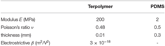
Table 1. Material and geometrical properties.
First study concerns with the shape reconfigurations of bilayer plates of a rectangular shape. Bilayer plates with three different planar dimensions, x1 × x2, 50 × 50 mm2, 50 × 25 mm2, and 50 × 5 mm2 are subjected to a continuous increase of electric field in the terpolymer layer. Figure 2 illustrates the corresponding shape reconfigurations in the square bilayer plate at different electric fields. It is noticed that in a square plate at low electric field inputs (Figures 2A,B) the deformations are seen by uniform folding of the four corners to achieve a dome-like shape. This is expected as the electric field input generates the same axial stretch in the terpolymer layer along the planar axes. The in-plane stretch gradient through the bilayer plate thickness generates the same curvatures along both planar axes. It is noted that the folded surface is the neutral surface of the bilayer plate, which is determined from Equation (8), as discussed in section Mathematical Formulation of Thin-Multi-Layered Active Composites. This has a consequence that only shapes with zero Gaussian curvature can be attained by prescribing the electric field input to the terpolymer layer. This is seen by snap-through shape reconfigurations when the electric field input is increased (Figures 2C–E) in order to achieve developable surfaces. The stable configuration with zero Gaussian curvature is associated with bending about a single planar axis. After the stable shape from the snap-through deformation is achieved, increasing electric field will lead to a rolling of the plate about the single planar axis. Figure 3 illustrates the corresponding Gaussian curvature of the square bilayer plate. It is seen that close to the snap-through state (Figures 3B–C), the Gaussian curvature has nearly zero magnitude. Once the stable configuration is achieved, the Gaussian curvature is zero (Figures 3D–E), except near the edges. Unlike the square plate, the rectangular plates immediately achieve a stable bending configuration about the axis with shorter dimension (Figures 4, 5). It is noted that the edge warping leads to a corkscrew-like shape, which can be clearly seen from a top view angle in all cases (Figure 6).

Figure 2. Bistable folding of square plate. (A) Electric field 9 MV/m; (B) electric field 15 MV/m; (C) electric field 18 MV/m; (D) electric field 68 MV/m; and (E) electric field 86 MV/m.
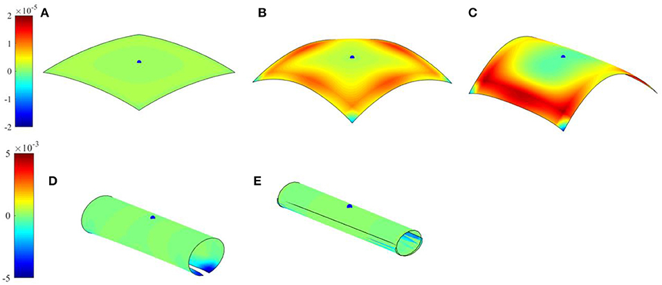
Figure 3. Gaussian curvature of folded square plate. (A) Electric field 9 MV/m; (B) electric field 15 MV/m; (C) electric field 18 MV/m; (D) electric field 68 MV/m; and (E) electric field 86 MV/m.
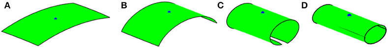
Figure 4. Folding of 50 × 25 rectangular plate. (A) Electric field 25 MV/m; (B) electric field 43 MV/m; (C) electric field 68 MV/m; and (D) electric field 86 MV/m.
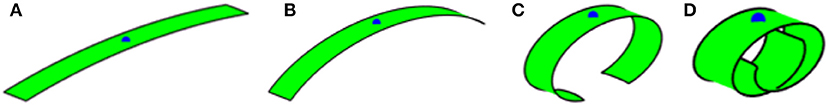
Figure 5. Folding of 50 × 5 rectangular plate. (A) Electric field 25 MV/m; (B) electric field 43 MV/m; (C) electric field 68 MV/m; and (D) electric field 86 MV/m.
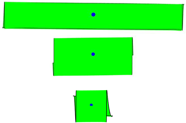
Figure 6. Top view of folded shapes of rectangular plates showing corkscrew shapes.
To further illustrate the influence of single or double curvature changes of bilayer plates, parametric studies on both square and rectangular plates are presented. Figure 7 shows the shape reconfigurations of square plates when the through thickness electric field input is assumed to only create an in-plane stretching about one planar axis. It is seen that the plate immediately bends about a single axis perpendicular to the in-plane stretching axis. The effect of Poisson's ratio on the shape reconfigurations is also examined, as shown in Figure 7. The Poisson's effect results in a slight edge outward bending, perpendicular to the global rotation axis, due to the contraction of the plate perpendicular to the stretching direction. Comparing the cases with and without Poisson's effect, the Poisson's effect results in more pronounced folding, as shown by the first principal curvature contours in Figure 8. The second principal curvatures are nearly zero and thus are not reported here. Figure 9 illustrates shape changes in a rectangular plate when the electric field input induces stretching only along the longitudinal axis of the plate. The influence of the Poisson's ratio is also studied. As expected a simple bending is seen in all cases. When the influence of the Poisson's ratio is removed, the response reduces to bending of a beam. Comparing the shape changes in Figures 4, 9, it is seen that the beam model can give a reasonable approximation of the deformation when the plate has a relatively large in-plane aspect ratio. Ignoring the influence of Poison's effect shows a negligible effect when the plate is under small curvatures (Figure 9A). Figure 10 presents the shape reconfigurations of a rectangular plate when the electric field input induces stretching only along the lateral axis of the plate. The influence of Poisson's ratio is also investigated. It is seen that in this example, the longitudinal contraction of the bilayer plate due to stretching of the terpolymer layer in the lateral direction induces an anticlastic shape with one axis of bending dominates the shape changes.

Figure 7. Folding of square plate, m2 = 0. Top: with poisson's effect; bottom: without poisson's effect. (A) Electric field 25 MV/m; (B) electric field 43 MV/m; (C) electric field 68 MV/m; and (D) electric field 86 MV/m.
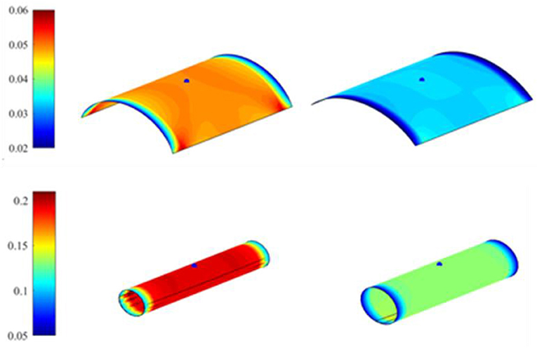
Figure 8. The corresponding first principal curvature with m2 = 0. Top: electric field 43 MV/m; bottom: electric field 86 MV/m. The figures on the left are responses with poisson's effect and figures on the right are responses without poisson's effect.
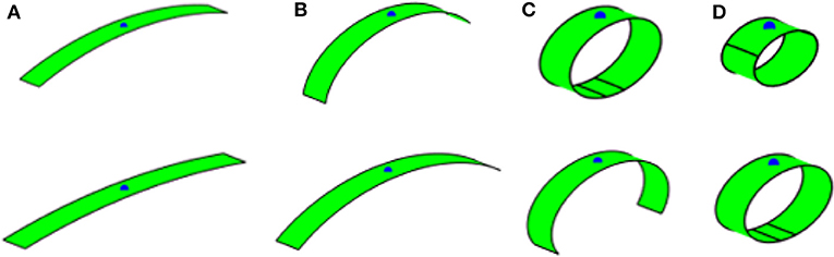
Figure 9. Folding of 50 × 5 rectangular plate, m1 = 0. Top: with poisson's effect; bottom: without poisson's effect. (A) Electric field 25 MV/m; (B) electric field 43 MV/m; (C) electric field 68 MV/m; and (D) electric field 86 MV/m.
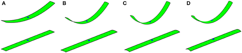
Figure 10. Folding of 50 × 5 rectangular plate, m2 = 0. Top: with poisson's effect; bottom: without poisson's effect. (A) Electric field 25 MV/m; (B) electric field 43 MV/m; (C) electric field 68 MV/m; and (D) electric field 86 MV/m.
Another case of folding of a triangular plate is shown in Figure 11. A snap-through behavior to form a rolling shape is also observed in order to maintain a stable shape with zero (or nearly zero) Gaussian curvature. Multi-stable shapes associated with snap-through mechanisms can also be achieved by prescribing different amplitude of electric field. For this purpose, a circular bilayer disk of a radius 25 mm is studied. Two different histories of prescribed electric field inputs are considered, referred as small and large increments. In the small increment input, a first stable shape configuration, which is associated with the lowest strain energy, can be achieved (see Figure 12 right). Once the stable configuration is achieved, increasing an electric field input will further fold the disk following this configuration. When a large increment input is considered, a different stable shape configuration is attained as the large increment input missed the electric field that drive the first mode, as shown in Figure 12 left. Further increasing the electric field yield to further folding of this stable shape. Figure 12D summaries the electric field inputs with small and large increments, and highlights the critical electric fields that induce snap-through mechanisms associated with the first and second stable configurations. The corresponding Gaussian curvatures of the disks, which indicate that the stable shapes have to attain zero Gaussian curvature, are depicted in Figure 13.
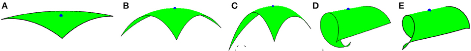
Figure 11. Folding of equilateral triangle plate. (A) Electric field 9 MV/m; (B) electric field 15 MV/m; (C) electric field 20 MV/m; (D) electric field 68 MV/m; and (E) electric field 86 MV/m.
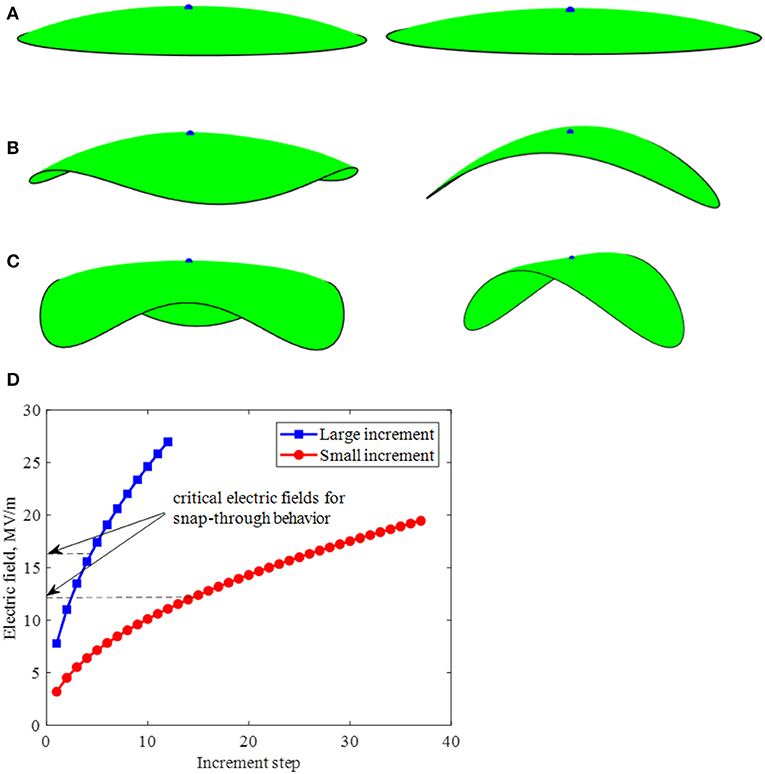
Figure 12. Folding of disk shape plate. Left: with large electric field increment; Right: with small electric field increment. (A) Electric field 11 MV/m; (B) electric field 17 MV/m; (C) electric field 19 MV/m; and (D) critical electric fields for the snap-through behavior under different increment.
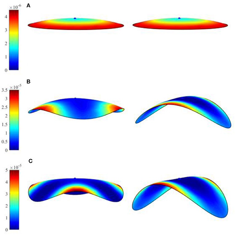
Figure 13. Gaussian curvature of folded disk shape plate. Left: with large electric field increment; Right: with small electric field increment. (A) Electric field 11 MV/m; (B) electric field 17 MV/m; and (C) electric field 19 MV/m.
The proposed approach is also capable in capturing an overall twisting shape reconfiguration of an active planar bilayer by arranging the placement of the active components in the bilayer. Figure 14 shows an example of a twisting of the active bilayer upon prescribing electric field input. It is seen that small magnitude of electric field induces initial bending deformations (Figures 14A–C), and increasing the non-uniform bending in the plate by increasing electric field in the active layers generates overall twisting shapes (Figures 14D–E). This twisting shape is attributed to the bending moments prescribed with off-axis angle from the longitudinal axis of the bilayer, which correspond to the placement of the active layer in the composite plate.

Figure 14. Twisting of 50 × 5 rectangular plate. (A) Electric field 25 MV/m; (B) electric field 43 MV/m; (C) electric field 68 MV/m; (D) electric field 86 MV/m; and (E) electric field 105 MV/m.
Finally, shape reconfigurations and retentions of bilayer plates comprising of terpolymer and LASMP layers are simulated. An electric field is first prescribed to the terpolymer layer to reconfigure the shapes of the bilayer, followed by radiating the LASMP layer. Upon radiation, the electric field input is removed and permanent shapes can be achieved. The properties of the terpolymer is given in Table 1. For the LASMP layer, the initial elastic properties are considered the same as the ones of PDMS layer, shown in Table 1. A parametric study is performed in order to investigate the effect of elastic modulus of the radiated LASMP on the overall shape retention behaviors. Figure 15 shows shape retentions of a 50 × 5 mm2 (rectangular) and 50 × 50 mm2 (square) bilayers from prescribing electric field 86 MV/m and complete irradiation (α = 1). It is seen that the shape retention depends strongly on the modulus of the LASMPs after irradiation. Stiffening the LASMPs by radiation will increase shape retention due to a minimal amount of spring back deformation. The shape retention can also be achieved in case of snap-through shape reconfiguration, as demonstrated for the square plate.
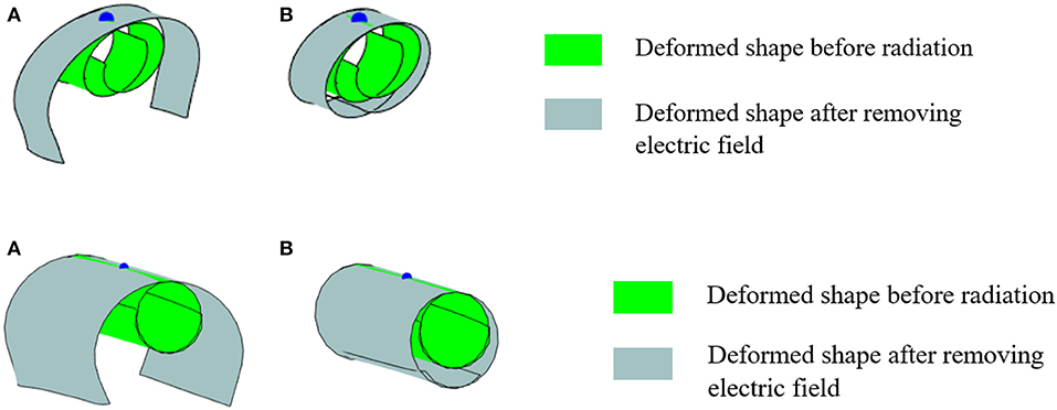
Figure 15. Deformed shapes of rectangular (top) and square (bottom) bilayers, comprising of LASMP substrate, after removing electric field. (A) and (B) .
Summary
This study discusses modeling and simulation of thin bilayer composites undergoing shape reconfigurations prescribed by an external electric field. The thin composites comprise of one active and one inactive (substrate) layers and the electric field input causes expansion/contraction in the active layer. The constitutive relation for the active material that describes the deformation due to external electric field only accounts for the in-plane normal components. Hence, the shape reconfiguration is achieved by rotations from high through thickness deformation gradients, which translate to corresponding bending moments. Furthermore, in a thin plate, the influence of transverse shear effect on the out of plane deformation is negligible. In analyzing the shape reconfigurations, a homogeneous planar surface out of the inactive layer (substrate) subjected to distributed bending moments, corresponding to the prescribed external electric field to the active layer, has been considered. The substrate is modeled as linear elastic and isotropic. A non-linear electro-mechanical coupling constitutive model is used for the electro-active layer. The co-rotational finite element method is then used to solve for the deformations of the planar surface.
In formulating the equations that govern the shape reconfigurations of an initially planar surface of a bilayer plate, two surfaces have been considered. In the first approach the shape reconfiguration is achieved by mapping the interface surface of the bilayer. For the considered polymer bilayers, the axial stretching or contraction of the interface surface from prescribing non-mechanical stimuli is relatively small, and hence does not contribute significantly to the shape changes. The shape changes are governed mainly by large rotations. In the second approach, the shape reconfiguration is achieved by mapping the neutral surface of the bilayer. Since the neutral surface does not experience stretching nor contraction, then the shape configurations that can be obtained from mapping the neutral surfaces are developable surfaces and the spontaneous shape reconfigurations have zero (or nearly zero) Gaussian curvature.
Several cases involving shape reconfigurations and snap-through behaviors of the planar surfaces of various geometries have been presented. It can be concluded that in all cases the reconfigured shapes have zero (or nearly zero) Gaussian curvature. When the prescribed electric field tends to deform the neutral surface to surfaces that are not developable, then snap-through behaviors occur since the constraints of the neutral surface do not allow forming such shapes. This has a consequence that the surfaces can be formed without inducing mechanical stresses, and thus surface damages due to shape reconfigurations are unlikely to occur. This study also shows that by controlling the placements of active layers in the bilayer systems, it is possible to create other shape reconfigurations that involve an overall out of plane twisting surface even though the prescribed electric field induces only local bending.
This study also considers a bilayer comprising of electro-active layer and light activated shape memory polymer (LASMP) layer. In case of the LASMP substrate is considered, a non-linear isotropic constitutive model based on a multiple natural configuration approach is used for the deformations of the substrate. It has been demonstrated that the shape retentions in the systems can be achieved upon removal of the electric field input by using a LASMP substrate.
Data Availability Statement
The datasets generated for this study are available on request to the corresponding author.
Author Contributions
RS was charged of analyzing bilayer with non-linear electro-mechanical activation and shape memory polymer, and performed analyses of shape reconfiguration. VT was charged of co-rotational finite element of shell element. AM was charged of developing constitutive material model for the polymer layers and directing this research topic.
Funding
This research was supported by the Air Force Office of Scientific Research (AFOSR) under grant FA9550-14-1-0234.
Conflict of Interest
The authors declare that the research was conducted in the absence of any commercial or financial relationships that could be construed as a potential conflict of interest.
Acknowledgments
The authors would like to also thank the Texas A&M Supercomputing Facility for access to the computing systems.
Supplementary Material
The Supplementary Material for this article can be found online at: https://www.frontiersin.org/articles/10.3389/fmats.2020.00097/full#supplementary-material
Footnote
1. ^When the elastic modulus of newly generated network is taken as , the curvatures and axial strains corresponding to electric field 100 MV/m are κ11 = κ22 = −0.1392 and , for a LASMP substrate with thickness 0.3 mm. The variation in neutral plane Δz = −2.31 × 10⁻⁴ mm, which is negligible compare to the thickness of substrate. Increasing will further reduce the values for , and Δz.
References
Alben, S., Balakrisnan, B., and Smela, E. (2011). Edge effects determine the direction of bilayer bending. Nano Lett. 11, 2280–2285. doi: 10.1021/nl200473p
Bartels, S., Bonito, A., Muliana, A. H., and Nochetto, R. H. (2018). Modeling and simulation of thermally actuated bilayer plates. J. Comput. Phys. 354, 512–528. doi: 10.1016/j.jcp.2017.10.044
Brown, W. H. (1916). The mechanism of movement and the duration of the effect of stimulation in the leaves of Dionaea. Am. J. Bot. 68–90. doi: 10.1002/j.1537-2197.1916.tb05404.x
Celli, P., Gonella, S., Tajeddini, V., Muliana, A., Ahmed, S., and Ounaies, Z. (2017). Wave control through soft microstructural curling: bandgap shifting, reconfigurable anisotropy and switchable chirality. Smart Mater. Struct. 26:035001. doi: 10.1088/1361-665X/aa59ea
Chen, Z., Guo, Q., Majidi, C., Chen, W., Srolovitz, D. J., and Haataja, M. P. (2012). Nonlinear geometric effects in mechanical bistable morphing structures. Phys. Rev. Lett. 109:114302. doi: 10.1103/PhysRevLett.109.114302
Crawley, E. F., and De Luis, J. (1987). Use of piezoelectric actuators as elements of intelligent structures. AIAA J. 25, 1373–1385. doi: 10.2514/3.9792
Dawson, C., Vincent, J. F., and Rocca, A.-M. (1997). How pine cones open. Nature 390:668. doi: 10.1038/37745
Daynes, S., Diaconu, C., Potter, K., and Weaver, P. (2010). Bistable prestressed symmetric laminates. J. Compos. Mater. 44, 1119–1137. doi: 10.1177/0021998309351603
Dimitriadis, E., Fuller, C., and Rogers, C. (1991). Piezoelectric actuators for distributed vibration excitation of thin plates. J. Vib. Acoust. 113, 100–107. doi: 10.1115/1.2930143
Drozdov, A. (2016). Modeling the response of polymer–ionic liquid electromechanical actuators. Acta Mech. 227, 437–465. doi: 10.1007/s00707-015-1471-7
Felippa, C. A., and Haugen, B. (2005). A unified formulation of small-strain corotational finite elements: I. Theory. Computer Methods in Appl. Mech. Eng. 194, 2285–2335. doi: 10.1016/j.cma.2004.07.035
Fernandes, R., and Gracias, D. H. (2012). Self-folding polymeric containers for encapsulation and delivery of drugs. Adv. Drug Deliv. Rev. 64, 1579–1589. doi: 10.1016/j.addr.2012.02.012
Guest, S., and Pellegrino, S. (2006). Analytical models for bistable cylindrical shells. Proc. R. Soc. A: Math, Phy. Eng. Sci. 462, 839–854. doi: 10.1098/rspa.2005.1598
Henke, M., Sorber, J., and Gerlach, G. (2012). Multi-layer beam with variable stiffness based on electroactive polymers. electroactive polymer actuators and devices (EAPAD) 2012. Int. Soc. Optics Photonics. 8340:83401P. doi: 10.1117/12.915138
Hyer, M. W. (1982). The room-temperature shapes of four-layer unsymmetric cross-ply laminates. J. Compos. Mater. 16, 318–340. doi: 10.1177/002199838201600406
Janbaz, S., Hedayati, R., and Zadpoor, A. (2016). Programming the shape-shifting of flat soft matter: from self-rolling/self-twisting materials to self-folding origami. Mater. Horiz. 3, 536–547. doi: 10.1039/C6MH00195E
Jiang, X., Pezzulla, M., Shao, H., Ghosh, T. K., and Holmes, D. P. (2018). Snapping of bistable, prestressed cylindrical shells. EPL (Europhysics Letters). 122:64003. doi: 10.1209/0295-5075/122/64003
Ko, H., and Javey, A. (2017). Smart actuators and adhesives for reconfigurable matter. Acc. Chem. Res. 50, 691–702. doi: 10.1021/acs.accounts.6b00612
Kuo, J.-N., Lee, G.-B., Pan, W.-F., and Lee, H.-H. (2005). Shape and thermal effects of metal films on stress-induced bending of micromachined bilayer cantilever. Jpn. J. Appl. Phys. 44:3180. doi: 10.1143/JJAP.44.3180
Kuravi, C., Muliana, A., and Rajagopal, K. R. (2012). Controlling the deformation in elastic and viscoelastic structures due to temperature and moisture changes using piezoelectric actuators. J. Intell. Mater. Syst. Struct. 23, 1949–1967. doi: 10.1177/1045389X12455721
Lendlein, A., Jiang, H., Jünger, O., and Langer, R. (2005). Light-induced shape-memory polymers. Nature. 434, 879–882. doi: 10.1038/nature03496
Long, K. N., Scott, T. F., Dunn, M. L., and Qi, H. J. (2011). Photo-induced deformation of active polymer films: single spot irradiation. Int. J. Solids Struct. 48, 2089–2101. doi: 10.1016/j.ijsolstr.2011.02.027
Ma, M., Guo, L., Anderson, D. G., and Langer, R. (2013). Bio-inspired polymer composite actuator and generator driven by water gradients. Science 339, 186–189. doi: 10.1126/science.1230262
Mailen, R. W., Liu, Y., Dickey, M. D., Zikry, M., and Genzer, J. (2015). Modelling of shape memory polymer sheets that self-fold in response to localized heating. Soft Matter. 11, 7827–7834. doi: 10.1039/C5SM01681A
Meng, H., and Hu, J. (2010). A brief review of stimulus-active polymers responsive to thermal, light, magnetic, electric, and water/solvent stimuli. J. Intell. Mater. Syst. Struct. 21, 859–885. doi: 10.1177/1045389X10369718
Muliana, A. (2015). Large deformations of nonlinear viscoelastic and multi-responsive beams. Int. J. Non Linear Mech. 71, 152–164. doi: 10.1016/j.ijnonlinmec.2014.12.001
Nemat-Nasser, S. (2002). Micromechanics of actuation of ionic polymer-metal composites. J. Appl. Phys. 92, 2899–2915. doi: 10.1063/1.1495888
Parthasarathy, S. S., Muliana, A., and Rajagopal, K. (2016). A fully coupled model for diffusion-induced deformation in polymers. Acta Mech. 227, 837–856. doi: 10.1007/s00707-015-1483-3
Russell, T. (2002). Surface-responsive materials. Science 297, 964–967. doi: 10.1126/science.1075997
Scott, T. F., Schneider, A. D., Cook, W. D., and Bowman, C. N. (2005). Photoinduced plasticity in cross-linked polymers. Science 308, 1615–1617. doi: 10.1126/science.1110505
Sheridan, R., Roche, J., and Lofland, S. E. (2014). Numerical simulation and experimental validation of the large deformation bending and folding behavior of magneto-active elastomer composites. Smart Mater. Struct. 23:094004. doi: 10.1088/0964-1726/23/9/094004
Smela, E., Inganäs, O., and Lundström, I. (1995). Controlled folding of micrometer-size structures. Science 268, 1735–1738. doi: 10.1126/science.268.5218.1735
Stoychev, G., Turcaud, S., Dunlop, J. W., and Ionov, L. (2013). Hierarchical multi-step folding of polymer bilayers. Adv. Funct. Mater. 23, 2295–2300. doi: 10.1002/adfm.201203245
Stoychev, G., Zakharchenko, S., Turcaud, S., Dunlop, J. W., and Ionov, L. (2012). Shape-programmed folding of stimuli-responsive polymer bilayers. ACS Nano. 6, 3925–3934. doi: 10.1021/nn300079f
Tajeddini, V., and Muliana, A. (2015). Nonlinear deformations of piezoelectric composite beams. Compos. Struct. 132, 1085–1093. doi: 10.1016/j.compstruct.2015.06.041
Tajeddini, V., and Muliana, A. (2017). Deformations of flexible and foldable electro-active composite structures. Compos. Struct. 160, 280–291. doi: 10.1016/j.compstruct.2016.09.069
Timoshenko, S. (1925). Analysis of bi-metal thermostats. Josa 11, 233–255. doi: 10.1364/JOSA.11.000233
Vandenbrink, J. P., Brown, E. A., Harmer, S. L., and Blackman, B. K. (2014). Turning heads: the biology of solar tracking in sunflower. Plant Sci. 224, 20–26. doi: 10.1016/j.plantsci.2014.04.006
Xue, C., Pan, E.-N., Zhang, S., and Chu, H. (2011). Large deflection of a rectangular magnetoelectroelastic thin plate. Mech. Res. Commun. 38, 518–523. doi: 10.1016/j.mechrescom.2011.07.003
Ye, C., Nikolov, S. V., Geryak, R. D., Calabrese, R., Ankner, J. F., Alexeev, A., et al. (2016). Bimorph silk microsheets with programmable actuating behavior: experimental analysis and computer simulations. ACS Appl. Mater. Interfaces 8, 17694–17706. doi: 10.1021/acsami.6b05156
Yuan, Z., Muliana, A., and Rajagopal, K. (2017a). Quasi-linear viscoelastic modeling of light-activated shape memory polymers. J. Intell. Mater. Syst. Struct. 28, 2500–2515. doi: 10.1177/1045389X17689936
Keywords: folding, polymer bilayer, electro-mechanical, shape memory polymer, snap-through, developable surface
Citation: Song R, Tajeddini V and Muliana A (2020) Modeling and Simulation of Thin Layered Composites Under Non-mechanical Stimuli. Front. Mater. 7:97. doi: 10.3389/fmats.2020.00097
Received: 12 November 2019; Accepted: 30 March 2020;
Published: 29 April 2020.
Edited by:
Rani Elhajjar, University of Wisconsin–Milwaukee, United StatesReviewed by:
Mirella Ramirez, National Autonomous University of Mexico, MexicoGhulam Hussain, Ghulam Ishaq Khan Institute of Engineering Sciences and Technology, Pakistan
Copyright © 2020 Song, Tajeddini and Muliana. This is an open-access article distributed under the terms of the Creative Commons Attribution License (CC BY). The use, distribution or reproduction in other forums is permitted, provided the original author(s) and the copyright owner(s) are credited and that the original publication in this journal is cited, in accordance with accepted academic practice. No use, distribution or reproduction is permitted which does not comply with these terms.
*Correspondence: Anastasia Muliana, YW11bGlhbmFAdGFtdS5lZHU=
†Present Address: Vahid Tajeddini, Ford Motor Company, Dearborn, MI, United States