- 1Science and Technology on Scramjet Laboratory, College of Aerospace Science and Engineering, National University of Defense Technology, Changsha, Hunan, China
- 2Science and Technology on Thermostructural Composite Materials Laboratory, Northwestern Polytechnical University, Xi'an, China
- 3NPU-SAS Joint Research Center of Advanced Ceramics, Northwestern Polytechnical University, Xi'an, China
- 4Department of Mechanical Engineering, Tsinghua University, Beijing, China
- 5State Key Laboratory of Tribology, Tsinghua University, Beijing, China
- 6Institute of Metal Research, Chinese Academy of Sciences, Shenyang, China
In this work, alumina ceramics were formed via stereolithography-based 3D printing technology in order to fabricate ceramic cores in a fast and cost-effective way. Effects of holding time during sintering on microstructure and properties of alumina ceramics were investigated. Sintered alumina ceramics were made up of layered structures due to layer-by-layer forming method. In addition, interlayer spacing decreased with the increase in holding time. Average particle size, shrinkage, crystallite size, flexural strength, and hardness increased with the increase in holding time due to strong interfacial bonding among alumina particles. Open porosity decreased slightly as holding time increased. Moreover, it was found that holding time had little influence on bulk density, phase composition, and chemical bonds of the ceramics. The shrinkage in Z direction was about 1.8 times higher than that in X or Y directions due to layered structure caused by 3D printing forming method. The optimum holding time was 90 min, which resulted in ceramics with interlayering spacing of 11.8 μm, shrinkage of 2.1% in X direction, 2.1% in Y direction, and 4.1% in Z direction, flexural strength of 20.7 MPa, nano-indentation hardness of 17.6 GPa, Vickers hardness of 114.3 HV, bulk density of 2.5 g/cm3, and open porosity of 39.0%.
Introduction
Alumina ceramic core is a complex part with fine structure, which can be used to manufacture high-temperature hollow turbine blades because it provides efficient cooling passage for the blades (Gromada et al., 2015). Alumina ceramic has excellent properties, such as low thermal expansion coefficient, high chemical stability, and good high-temperature performance (Ikeda et al., 2011). It is therefore extensively applied in the astronautics engineering and material engineering fields related to high-temperature environments (Chen et al., 2019). One of the most difficult and significant problems of preparing alumina ceramic core is its preparation method and prototyping precision. Traditionally, the ceramic core is prepared through investment casting method. As a result, limitations have occurred in the fabrication process, including long production cycle, high cost, and low precision (Wu et al., 2009; Li et al., 2019a,b,c).
The emergence and rapid development of stereolithography-based 3D printing technology offers a new method to solve the above-mentioned problems. 3D printing technology integrates computer-aided design, material processing, and molding, which are based on digital model files. Using this technique, special metallic materials, inorganic materials, and medical biomaterials are stacked layer-by-layer in accordance with extrusion, sintering, melting, light curing, jet, and other methods to create the desired physical objects (Bose et al., 2013; Sun et al., 2013; Gebler et al., 2014; Liu et al., 2020). 3D printing technology has been successfully applied in the field of metal materials and polymer materials. However, there are still many technical problems in the field of inorganic non-metallic ceramics (Shao et al., 2017). One of the most significant problems of 3D printing technology is the deformation and cracks generated during sintering process, especially for ceramic cores with complex structures (Scheithauer et al., 2015). Moreover, ceramic core needs to meet certain mechanical performance and physical property requirements, such as flexural strength >20 MPa and open porosity higher than 20% (Park et al., 2019). Therefore, the sintering process is a key factor, which influences the deformation, cracking, and mechanical properties of the ceramics.
At present, the studies on stereolithography-based 3D printing of ceramic cores are still at an early stage. Tang et al. (2018) applied 3D printing technology to fabricate alumina ceramic cores, which were sintered at 1,600°C for 180 min. The products exhibited high strength and could satisfy the requirements of ceramic cores in alloy casting. Yang et al. (2019) fabricated CaO-based ceramic mold by stereolithography, which was sintered at 1,400°C for 180 min and obtained a bending strength of 14.1 MPa. Halloran (2016) explored the depth, the width, and the profile during curing process, which related to the optical properties of monomer, slurry, and photo-active components in stereolithography. The preparation of ceramic cores involves the fabrication of green bodies, debinding, and sintering processes. The sintering process should be first optimized to achieve a number of key requirements, which including moderate flexural strength, low shrinkage, and moderate open porosity (Giordano et al., 1995). The holding time during sintering involves a process of mass transfer, grain boundary migration, and particle growth (Gao et al., 2000). Appropriate holding time can eliminate pores and promote densification, but a very long holding time would decrease the density, due to abnormal growth of particles and deformation of green bodies, and reduce the mechanical properties of materials (Cha and Hong, 2003; Liu et al., 2018; Cheng et al., 2019; Tangcharoen et al., 2019). Therefore, the holding time should not be blindly extended. In this research, the effect of holding time on the microstructure and properties of 3D printed alumina ceramics was investigated to optimize the sintering process. Several characterization and test methods were applied to analyze and evaluate the sintering effect. Finally, the flexural strength, shrinkage, and open porosity of the sintered alumina ceramics were measured to evaluate whether they could meet the requirements of ceramic core.
Experimental Procedure
Fabrication of Alumina Green Bodies
The alumina green bodies (Li et al., 2019a,b,c) (50 × 4 × 3 mm) were printed via a 3D printer (AutoceraM, Beijing Ten Dimensions Technology Co., Ltd.) with LED light source and 405 nm wavelength. During the printing process, the exposure energy, the single layer exposure time, and the layer thickness were 10 mW/cm2, 10 s and 0.1 mm, respectively. The alumina powder (AW-SF, purity ≥ 99.0%, Henan Hecheng Inorganic New Material Co., Ltd.) was dried at 200°C for 5 h in a blast air oven and then used for preparation of the ceramic slurry. The ceramic slurry was prepared by the following procedure: 495 g of Al2O3 powder was added to 100 g of photosensitive resin (Al100-1, Beijing Ten Dimensions Technology Co., Ltd.) slowly, and the mixture was stirred vigorously. After the slurry was mixed uniformly, it was ball-milled for 2 h with a planet-type grinding mill at the rate of 400 rpm. Then, the slurry was vacuum defoamed for 10 min and obtained the final alumina ceramic slurry.
Debinding and Sintering Processes
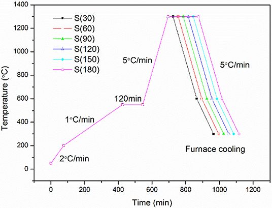
The green bodies were debinded and sintered in a muffle furnace (Hefei Ke Jing Materials Technology Co., Ltd. China). Firstly, the samples were heated to 200°C with a heating rate of 2°C/min. Secondly, the samples were heated to 550°C with a heating rate of 1°C/min and maintained for 2 h. Thirdly, the samples were heated to 1,300°C with a heating rate of 5°C/min and maintained for H minutes (H = 30, 60, 90, 120, 150, 180 min). Finally, the samples were cooled to 600°C with a heating rate of 5°C/min and subsequently cooled in a furnace. The samples were denoted as S(H), and H = 30, 60, 90, 120, 150, 180 min. The debinding and sintering profiles are illustrated in Figure 1.
Characterization
X-ray diffraction (XRD) curves were recorded on a Bruker D8 FOCUS (Bruker Corporation, Germany) X-ray diffractometer with Cu Kα radiation. Firstly, the diffraction angle of 2θ was scanned over the range from 10 to 90°. Secondly, the voltage was 40 kV, and the generator current was 30 mA. Thirdly, the scan rate was 0.02° s−1 per step. The crystallite size of Al2O3 was calculated using the following Scherrer's equation from the peak at 2θ = 35.3° (Mazloumi et al., 2006).
where, d is the average crystallite size of Al2O3 (nm), K is the Scherrer constant (0.89 in the present case), λ is the wavelength of X-ray (0.154056 nm), and B is the peak width at half-height of Al2O3.
Raman spectra of the samples were measured on a Confocal Raman Microscope System (Alpha300R, WITec) with a laser source of 532 nm, power of 50 mW, and slit width of 50 μm. X-ray photoelectron spectroscopy (XPS) was performed using an Axis Supra (Shimadzu) photoelectron spectrometer. Scanning electron microscope (SEM) images were obtained using a Helios G4 CX microscope (FEI Corporation). Transmission electron microscopy (TEM) images were obtained using a Tecnai G2 F20 system (FEI Corporation). Energy spectrum analysis (EDS) was also conducted to obtain the elemental composition of the samples.
Bulk densities of the alumina ceramics were measured with the Archimedes method. Accuracy of the balance was 0.0001 g (Mettler Toledo, Switzerland) (Sun et al., 2005).
Flexural strength of the sintered samples was tested with an electronic universal testing machine (CMT4304, SUNS, China) using the three-point bending method. The loading speed was 0.5 mm/min, and the span was 30 mm. The calculation formula for flexural strength is shown as follows (Liu et al., 2013):
where σf is the bending strength (MPa), F is the maximum load (N), L is the span of lower fixture (mm), b is the width of the sample (mm), and d is the thickness of the sample (mm).
Surface roughness of the sample was measured by atomic force microscope (AFM, Dimension Icon, Bruker, USA), and the spring constant was 0.40 N/m (Ersu et al., 2009).
Nano-indentation test was performed using a nano-test apparatus (TI980, Hysitron, USA). Static indentation test was conducted at room temperature. First, the head approaches the surface of the sample at the speed of 2 mN/s, and after contacting the sample, it is loaded to the maximum load 10 mN for 5 s and unloaded for 5 s after reaching the maximum load sustained for 2 s. The load-displacement curve was recorded by the connected computer during the whole test, and 5 points were tested for each sample (Gong et al., 2005).
Vickers hardness test was performed on a Micro/Macro Automatic Hardness Testing system (LM248AT, LECO, USA). The load was 1,000 g, the dwell time was 15 s, and 5 points were tested for each sample.
Results and Discussion
Microstructure and Composition
The sample microstructure observed by SEM is shown in Figure 2. The results showed that delamination phenomenon existed in all the samples, which were sintered with different holding times. Cracks were observed in the samples sintered for 30 min, and the size of cracks was 4.1 μm. However, no cracks were found in the samples when the holding time during sintering was increased to 60 min or longer. Before the debinding and sintering processes, the green bodies were composed of alumina powder and photosensitive resin. During the debinding process, photosensitive resin was heated and turned into gases, such as carbon dioxide and water vapor. These volatile components were removed from the green bodies, and only alumina powder was left in the samples after the debinding process (Choi and Jeong, 2009), Then, the sintering process was conducted to promote the alumina particles to stick together. Sintering is the densification process of alumina green bodies at high temperature. When the sintering temperature and holding time increase, the alumina particles bond with each other, the particles grow, and the pores and particle boundaries gradually decrease. Through material transfer, the total volume shrinks, the density increases, and the sample finally becomes a hard-polycrystalline sintered body with a certain microstructure (Bodišov et al., 2007). When the holding time was only 30 min, the particles did not grow large enough, and there were voids between particle boundaries. Therefore, cracks were found in the 30 min sintered samples. As the holding time increased to 60 min and above, the particles grew and the voids between particle boundaries decreased, so the cracks disappeared. This demonstrates that 30 min was too short for the sintering process, while 60 min and longer was suitable to decrease cracks in the alumina ceramic.
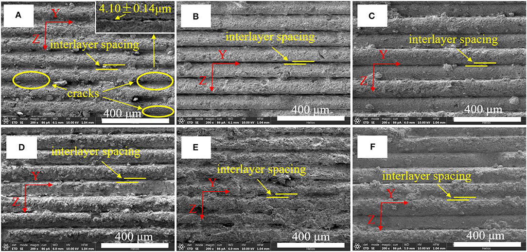
Figure 2. The layered structure of sintered samples observed by SEM: (A) 30 min; (B) 60 min; (C) 90 min; (D) 120 min; (E) 150 min; (F) 180 min.
Figure 2 also shows that all the samples were composed of layers, as the 3D printed alumina ceramics have lamination structure. The green bodies were printed layer-by-layer via 3D printer, the degree of curing reaction among Z direction are not uniform, so the binding force of the layers in the Z direction was relatively weak compared with that in X and Y directions. As the green bodies were debinded and sintered, the adhesion strength between particles in Z direction was weak, so interlayer spacing existed in the alumina ceramics. The layered structure common exists in 3D printed samples. For example, Schwentenwein and Homa (2015) observed layer-by-layer structure in dense alumina ceramics fabricated through stereolithography based 3D printing technology. Azarmi and Amiri (2019) studied the microstructural evolution during fabrication of alumina ceramic using stereolithography technique, and demonstrated the formation of layered structure for the samples as the 3D model of the parts was sliced to filmy sections, which were printed layer-by-layer on the printing platform. Hu et al. (2018) found that the force of separation during layer printing was the key influencing factor for achieving successful printing process. Firstly, the complex green bodies were printed layer-by-layer, followed secondly by the removal of binders, and thirdly, the ceramics were densified through high-temperature thermal treatment. The layered structures of the above ceramics were consistent with the layer-by-layer structure of the samples shown in Figure 2.
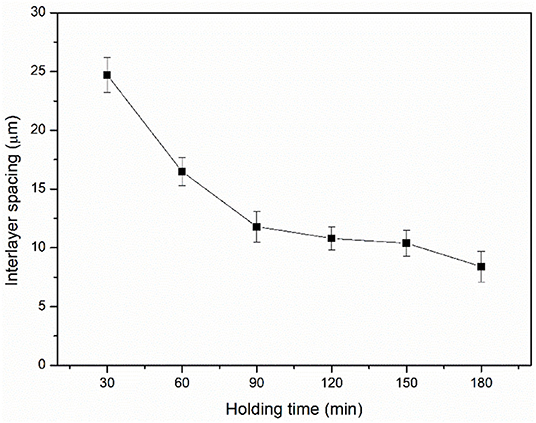
Interlayer spacing in the alumina ceramics shown in Figure 2 was measured and the results are shown in Figure 3. It was found that the interlayer spacing decreased as the holding time increased. The interlayer spacing was 24.7 μm when sintered for 30 min and 8.4 μm when sintered for 180 min. The interlayer spacing decreased significantly when the holding time increased to 60 and 90 min. When the holding time was higher than 90 min, the variation was relatively low. This means that the holding time is a key parameter that affects the interlayer spacing of alumina ceramics. Based on the above results, 90 min was considered as a suitable holding time during sintering process.
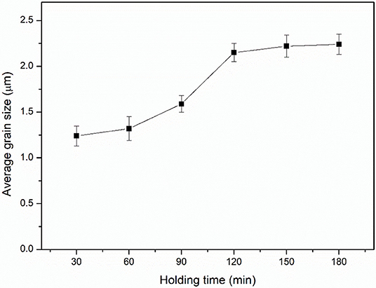
Figure 4 shows the microstructure of intergranular bonding of alumina ceramics sintered with different holding times. When sintered for 30 min, there were large pores in the samples with pore size of about 6.0 μm. As the holding time increased to 60 min, the size of pores decreased to about 4.1 μm. As the holding time during sintering was further increased to 90 min and more, the pores disappeared. This phenomenon indicates that increasing the holding time can promote the pores in the sample to decrease and gradually disappear. Some researchers have found that the microstructure could affect the mechanical properties and there are some relationships between microstructure and mechanical properties. For example, Li et al. (2019d) fabricated porous alumina ceramic with bimodal pore size distribution and found that the binding strength decreased as the porosity increased. Wang et al. (2009) researched fine alumina-zirconia ceramics and found that increase in holding time could increase the density of samples and the grain size of particles. Average grain size of the alumina ceramic was measured, and the results are shown in Figure 5. Average grain sizes of the samples were 1.2, 1.3, 1.6, 2.2, 2.2, and 2.2 μm when the holding times were 30, 60, 90, 120, 150, and 180 min, respectively. The average grain size increased as the holding time increased over the range of 30–120 min. Then the average grain size reached a constant value when the holding time was in the range of 120–180 min. This indicated that the grain size increased when the holding time was in a relatively small range (30~120 min), while the grain size did not increase further when the holding time was more than 120 min. Teng et al. (2007) researched the effect of alumina grain size on the flexural properties of alumina-based ceramics and found that nano-scale alumina ceramic with high density and flexural strength was comparable with micro-scale alumina ceramics due to the grain fining, grain boundary reinforcement, and transgranular fracture mode. Therefore, 120 min was considered a sufficient holding time, and longer holding time could not affect the grain size significantly.
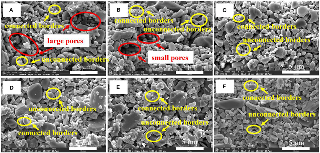
Figure 4. SEM images of sintered samples: (A) 30 min; (B) 60 min; (C) 90 min; (D) 120 min; (E) 150 min; (F) 180 min.
Micromorphology of the sample sintered for 90 min was observed by TEM, and the images are shown in Figure 6. The TEM images (Figures 6A,B) show that the particle size was uniform, and some of the particles were connected together. The size of particles may affect the mechanical properties of alumina ceramic. Some researchers observed alumina ceramics by TEM and found that nanostructures of the ceramics were related to their physical and mechanical properties. For example, Calvié et al. (2012) performed real-time TEM observation for alumina ceramic of nano-particles during compression and found that of small particles 40 nm in diameter could experience severe plastic deformation without failure, and brittle fracture was observed in the 120-nm-sized nano-particles. Nie et al. (2002) analyzed alumina coatings fabricated using plasma electrolysis and observed an inner layer with nanocrystalline (1.5 μm) and an intermediate layer with nanocrystalline (50–60 nm) in the coating by TEM. Then, the higher resistance to wear and corrosion could be partly attributed to the occurrence of these interlayers.
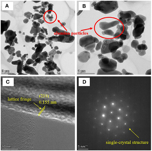
Figure 6. TEM images of 90 min sintered samples: (A) TEM image; (B) Further enlarged TEM image; (C) HRTEM image; (D) Selected area electron diffraction pattern.
Clear lattice fringe of the alumina ceramic was observed in HRTEM image (Figure 6C), and the lattice spacing was 0.155 nm, which represents the (211) crystallographic plane of α-alumina. Selected area electron diffraction pattern (Figure 6D) indicates that the sintered alumina ceramic was a single crystal structure. Single crystal structure was also observed by Perrie et al. (2005) who researched the femtosecond laser micro-structuring of alumina ceramic. They found that, according to the optimizing of the processing parameters, the residual surface roughness of the samples could be decreased below that of the pristine surface of Ra = 0.8 μm, and the debris produced consisted primarily of single crystal nanoparticles for alumina particles with diameters increased from 20 nm to 1 μm and with the average diameter of 300 nm.
The elemental distribution obtained from TEM images of 90 min sintered samples is shown in Figure 7. The elemental distribution images (Figures 7A,B) show the uniform distribution of Al and O elements. The distribution of C element (Figure 7C) represent the carbon film used to prepare the TEM samples. The EDS curve (Figure 7D) indicates that the main elements in samples were Al, O, and C.
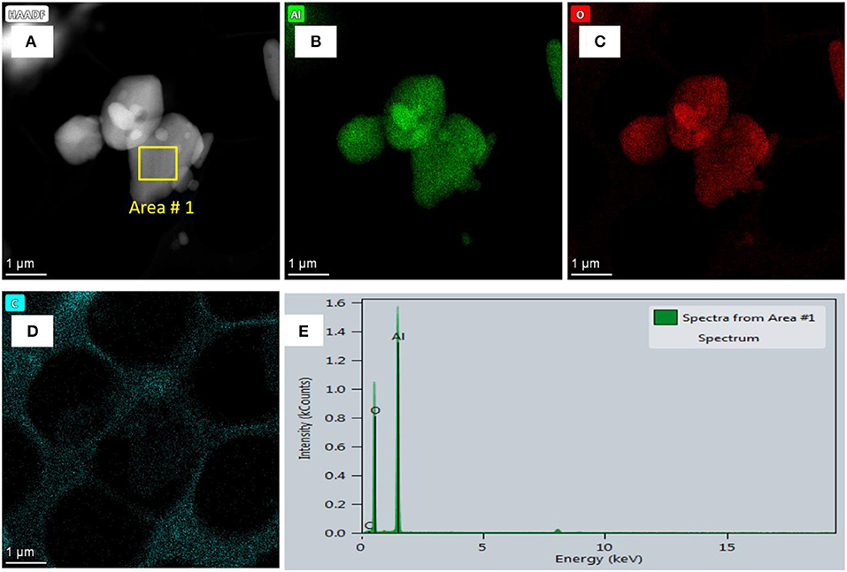
Figure 7. Elemental distribution obtained from TEM images of 90 min sintered samples: (A) HAADF image; (B) Distribution of Al element; (C) Distribution of O element; (D) Distribution of C element; (E) EDS curve.
Phase composition data obtained from XRD of the alumina ceramics sintered with different holding times are shown in Figure 8A. The XRD patterns indicate that all the samples were composed of α-alumina, and no phase transitions occurred during sintering in air for different holding times. The peaks in Figure 8A indicate the presence of α-alumina phase (Eklund et al., 2008). Figure 8B shows the change trend of crystallite size of alumina ceramics with sintering holding time. The results indicated that the crystallite size increased as the holding time increased, but the growth rate was different. In the range of 30–60 min, the crystallite size increased from 53.2 to 53.5 nm, with variation of only 0.3 nm. As the holding time increased from 90 to 120 min, the crystallite size increased from 67.0 to 76.2 nm, which shows a relatively fast growth rate. However, as the holding time was further extended, the growth rate began to slow. The crystallite size increased from 78.5 to 84.1 nm as the holding time increased from 150 to 180 min. This phenomenon indicates that relatively short holding time during the sintering process would lead to relatively small crystallite size, and extending the holding time of sintering process was beneficial to increase the crystallite size of alumina ceramics. Some researchers found that the crystallite size affects the microstructure of sintered ceramics. For example, Shojai and Mäntyl (2001) investigated the effect of holding time on the properties of 3Y-ZrO2 membranes and found that (1) the grain growth was controlled and hindered by a solute drag mechanism due to the segregation of yttria in the grain boundaries, (2) low grain growth of the samples indicated that the movability of pores was higher than that of grain boundaries, and (3) impurities influenced the grain growth of Y-TZP through their effects on diffusion rate and grain boundaries mobility. This means that the growth rate of particles is influenced by a number of factors.
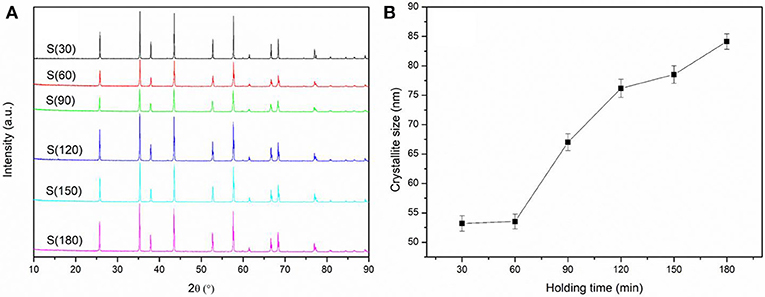
Figure 8. XRD results of alumina ceramic sintered with different holding times: (A) The XRD curves and (B) The crystallite size.
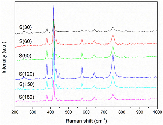
Raman spectra of the alumina ceramics sintered with different holding times are shown in Figure 9. The peaks of all of the samples were the same and located at 378, 418, 432, 451, 578, 645, and 751 cm−1, respectively. These data indicate that the samples consisted of α-alumina phase, in accordance with the results reported by (Kadleiková et al., 2001) on the Raman spectra of synthetic sapphire. The peak at 451 cm−1 represents the vibrations of Al-O bond (Mariotto et al., 1990; Reyes-López et al., 2013). Although the holding time during sintering process was different, the samples were sintered at the same temperature of 1,300°C at which the photosensitive resin was decomposed completely. Therefore, no C or O compounds were detected in the samples. The Raman results indicate that the holding time during sintering process did not affect the chemical composition of samples.
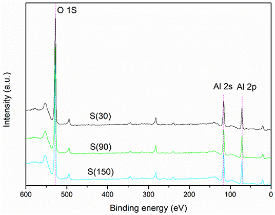
XPS curves of the alumina ceramic sintered with different holding times are shown in Figure 10. The peaks at 529, 117, and 72 eV represent O 1s, Al 2s, and Al 2p, respectively. The peaks of alumina ceramics sintered with different holding times were almost the same, indicating that the chemical bonds of different samples were similar. The holding time during the sintering process had little effect on the state of chemical bonds. The atomic ratio data obtained from XPS of alumina ceramic sintered with different holding times are shown in Table 1. It can be seen that the elemental content of different samples was basically consistent, and the holding time during sintering process did not affect the composition and content of each element. Klym (2017) applied XPS method to investigate the effect of holding time during sintering on MgO-Al2O3 nanoceramics and found that structural perfection of ceramics increased with holding time during sintering. This indicates that different sintering holding times would affect the chemical bonds in sample composed of various compounds. Since the object of this research was pure α-alumina, no change in chemical bonds was detected.
Physical Properties
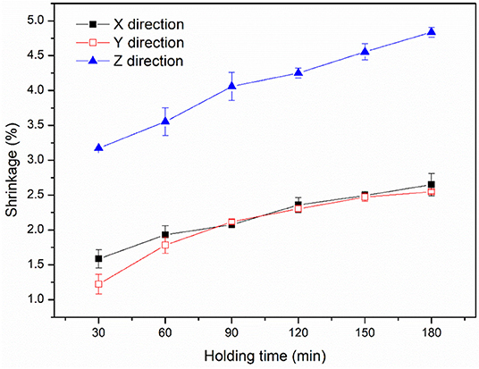
Shrinkage data of the alumina ceramic sintered with different holding times are shown in Figure 11. The results showed that the shrinkage in Z direction was different from that in X or Y directions. The shrinkage in Z direction was between 3.2 and 4.8%, the shrinkage in X direction was between 1.6 and 2.6%, and the shrinkage in Y direction was between 1.2 and 2.5%. The shrinkage in Z direction was about 1.8 times as much in X direction or Y direction. Moreover, the shrinkage increased as the holding time increased during sintering process. Chen et al. (2018) fabricated PZT ceramic with shrinkage of 30.8% and found that the shrinkage was induced by the combination and growth of the grains at high thermal temperature treatment. Guo et al. (2019) fabricated titanium dioxide ceramic with shrinkage of 51.1~70.4% and found that the shrinkage of X, Y, and Z directions of the sintered ceramics was anisotropic. Furthermore, the shrinkage in the Z direction was obviously greater than that in X direction or Y direction, which was mainly related to the reason of surface exposure.
The green bodies were fabricated by layer-by-layer forming method, which led to weak binding force in Z direction compared with X or Y direction. After the debinding and sintering processes, the weak binding force led to greater shrinkage. Therefore, the shrinkage in Z direction was about 1.8 times as much as that in X or Y directions. The low shrinkage would slowly decrease the deformation of the parts, especially for alumina ceramic core with complex structures. He et al. (2018) fabricated zirconia ceramic parts through stereolithography-based 3D printing technology and found that the sintered bodies displayed significant shrinkage of 35.26% after sintering. Brinckmann et al. (2018) fabricated SiC-based composite ceramics through stereolithography with shrinkage of 37%. Aduba et al. (2017) fabricated β-tricalcium phosphate through stereolithography with shrinkage of 7.14~12.91% and found that the shrinkage in Z direction was significantly greater than that in the other two build orientations. Thus, the shrinkage of sample fabricated through stereolithography method was relatively large due to the removal of photosensitive resin, which was introduced in the ceramic slurry for photopolymerization reaction.
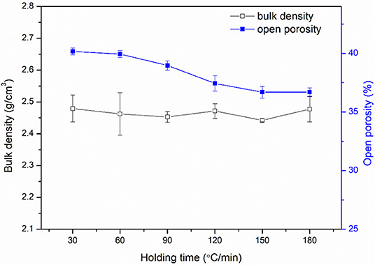
Bulk density, open porosity, growth rate, and variation tendency of growth rate of the sintered alumina ceramics with different holding times are shown in Figure 12. Bulk density was between 2.4 and 2.5 g/cm3, while the difference in bulk density among samples sintered with different holding times was very small, which indicated that the influence of holding time on bulk density was low. Open porosity of alumina ceramic sintered with different holding times was between 36.7 and 39.9%, which exhibited a slight variation. The slight variation was because the open porosity decreased as the holding time increased. During the sintering process, the main purpose of extending the holding time is to accelerate the densification of alumina ceramics, along with the migration of particles, rearrangement, and shrinkage. The increased holding time during sintering process promoted the particle growth, so the open porosity decreased slightly.
Mechanical Properties
Figure 13 shows the mechanical properties of samples, which include flexural strength, Vickers hardness, load-displacement curves, and nano-indentation derived hardness. As seen from Figure 13A, flexural strength increased from 15.6 to 22.2 MPa, Vickers hardness increased from 82.0 to 137.1 HV, and hardness obtained from nano-indentation test increased from 13.6 to 30.1 GPa as the holding time increased from 30 to 180 min. These results indicate that the flexural strength and hardness of alumina ceramics increased with the increase in holding time during the debinding process over the range of 30~180 min. According to Figures 2, 3, the interlayer spacing decreased as the holding time increased. According to Figure 4, increasing the holding time promoted the pores in the sample to decrease and gradually disappear. According to Figure 5, the average particle size increased as the holding time increased over the range of 30–120 min. The decreased interlayer spacing, decreased pores, and increased particle size may lead to the increase in flexural strength and hardness. Figure 12 shows that there was a slight decrease in open porosity as the holding time increased. According to Ryskewitsch equation (Yu et al., 2018), shown as follows, flexural strength of ceramic decreases as the porosity increases.
where σ is the strength (MPa), σ0 is the strength with porosity at 0 (MPa), p is the porosity (%), and α is a constant.
The hardness of alumina ceramic mainly depends on its crystal structure and microstructure. The variation tendency of hardness was similar to that of flexural strength. This may be because the interlayer spacing, pores, particle size, and open porosity had slight influence on the hardness. Wang (2013) fabricated alumina ceramic parts through stereolithography with a flexural strength of 327~472 MPa due to the high relative density of 98%. Tasaki et al. (2010) investigated the mechanical properties of alumina dental crowns fabricated through stereolithography, which exhibited the flexural strength of 587 MPa. Xing et al. (2017) investigated the mechanical properties of 3D printed ZrO2 ceramic through stereolithography, which showed a high flexural strength of 1,154 MPa. As the alumina ceramics prepared in this study are used in the field of ceramic core and need to be removed later, the strength cannot be too high. In order to evaluate the surface roughness of the alumina ceramics sintered with different holding times, the AFM was used to test the sample surface roughness. The results are shown in Figure 14. The results indicate that the surface roughness of different samples was similar and the holding time during sintering has little effect on the surface roughness.
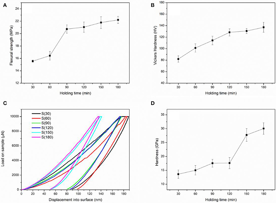
Figure 13. Mechanical properties of the samples sintered with different holding times: (A) Flexural strength; (B) Vickers hardness; (C) Load-displacement curves from nano-indentation tests; (D) Hardness obtained from nano-indentation tests.
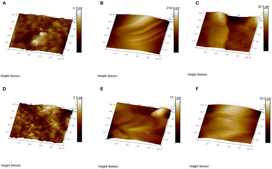
Figure 14. A three-dimensional diagram of the sample surface obtained from AFM with different holding times: (A) 30 min; (B) 60 min; (C) 90 min; (D) 120 min; (E) 150 min; (F) 180 min.
Conclusions
This paper investigated the influence of holding time during air debinding process on the microstructure, physical properties, and mechanical properties of 3D printed alumina ceramics. The conclusions can be summarized as follows:
(1) The interlayer spacing decreased as the holding time increased because the alumina green bodies were prepared by layer-by-layer forming method and extended sintering time. The average particle size, shrinkage, crystallite size, flexural strength, and hardness increased as the holding time increased due to the strong interfacial bonding among alumina particles.
(2) The open porosity decreased slightly as the holding time increased, and the holding time had little influence on the bulk density, phase composition, and chemical bonds of the ceramic sample. The shrinkage in Z direction was about 1.8 times greater than that in X or Y direction due to the layer structure formed by 3D printing preparation method.
(3) The optimum holding time was considered to be 90 min, which resulted in ceramic product with interlayering spacing of 11.8 μm, shrinkage of 2.1% in X direction, 2.1% in Y direction, and 4.1% in Z direction, flexural strength of 20.7 MPa, nano-indentation hardness of 17.6 GPa, Vickers hardness of 114.3 HV, bulk density of 2.5 g/cm3, and open porosity of 39.0%.
Data Availability Statement
All datasets generated for this study are included in the article/supplementary material.
Author Contributions
YP and HL wrote this paper. YoL revised this paper. YaL, KH, NW, ZL, JL, and SH helped to complete this paper.
Funding
This work was supported by National Key Research and Development Program of China (No. 2018YFB1106600) and the Chinese National Foundation for Natural Sciences under Contracts (Nos. 51672217 and 51572224).
Conflict of Interest
The authors declare that the research was conducted in the absence of any commercial or financial relationships that could be construed as a potential conflict of interest.
References
Aduba, D. C. J., Feller, K. D., and Williams, C. B. (2017). “An investigation of build orientation on shrinkage in sintered bioceramic parts fabricated by vat photopolymerization[C]//solid freeform fabrication 2017,” in Proceedings of the 28th Annual International Solid Freeform Fabrication Symposium - An Additive Manufacturing Conference (Austin).
Azarmi, F., and Amiri, A. (2019). Microstructural evolution during fabrication of alumina via laser stereolithography technique. Ceram. Int. 45, 271–278. doi: 10.1016/j.ceramint.2018.09.163
Bodišová K, Šajgalík, P., and Galusek D, Švančárek P. (2007). Two-stage sintering of alumina with submicrometer grain size. J Am. Ceram. Soc. 90, 330–332. doi: 10.1111/j.1551-2916.2006.01408.x
Bose, S., Vahabzadeh, S., and Bandyopadhyay, A. (2013). Bone tissue engineering using 3D printing. Mater. Today 16, 496–504. doi: 10.1016/j.mattod.2013.11.017
Brinckmann, S., Patra, N., Yao, J., Ware, T., Frick, C., and Fertig, I. I. I. R. (2018). Stereolithography of SiOC polymer-derived ceramics filled with SiC micronwhiskers. Adv. Eng. Mater. 20:1800593. doi: 10.1002/adem.201800593
Calvié, E, Joly-Pottuz, L., Esnouf, C., Clément, P., Garnier, V., Chevalier, J., et al. (2012). Real time TEM observation of alumina ceramic nano-particles during compression. J. Eur. Ceram. Soc. 32, 2067–2071. doi: 10.1016/j.jeurceramsoc.2012.02.029
Cha, S. I., and Hong, S. H. (2003). Microstructures of binderless tungsten carbides sintered by spark plasma sintering process. Mater. Sci. Eng. A. 356, 381–389. doi: 10.1016/S0921-5093(03)00151-5
Chen, Y., Bao, X., Wong, C., Cheng, J., Wu, H., Song, H., et al. (2018). PZT ceramics fabricated based on stereolithography for an ultrasound transducer array application. Ceram. Int. 44, 22725–22730. doi: 10.1016/j.ceramint.2018.09.055
Chen, Z., Li, J., Liu, C., Liu, Y., Zhu, J., and Lao, C. (2019). Preparation of high solid loading and low viscosity ceramic slurries for photopolymerization-based 3D printing. Ceram. Int. 45, 11549–11557. doi: 10.1016/j.ceramint.2019.03.024
Cheng, Z., Ye, F., Liu, Y., Qiao, T., Li, J., Qin, H., et al. (2019). Mechanical and dielectric properties of porous and wave-transparent Si3N4-Si3N4 composite ceramics fabricated by 3D printing combined with chemical vapor infiltration. J. Adv. Ceram. 8, 399–407. doi: 10.1007/s40145-019-0322-8
Choi, Y. C., and Jeong, M. S. (2009). Improvement of the field emission stability of carbon nanotube paste emitter by post-treatments. Carbon Lett. 10, 234–238. doi: 10.5714/CL.2009.10.3.234
Eklund, P., Sridharan, M., Sillassen, M., and Bøttiger, J. (2008). α-Cr2O3 template-texture effect on α-Al2O3 thin-film growth. Thin Solid Films. 516, 7447–7450. doi: 10.1016/j.tsf.2008.03.038
Ersu, B., Yuzugullu, B., Yazici, A., and Canay, S. (2009). Surface roughness and bond strengths of glass-infiltrated alumina-ceramics prepared using various surface treatments. J. Dentist. 37, 848–856. doi: 10.1016/j.jdent.2009.06.017
Gao, L., Hong, J. S., Miyamoto, H., and Rorre, S. (2000). Bending strength and microstructure of Al2O3 ceramics densified by spark plasma sintering. J. Eur. Ceram. Soc. 20, 2149–2152. doi: 10.1016/S0955-2219(00)00086-8
Gebler, M., Uiterkamp, A. J. M. S., and Visser, C. (2014). A global sustainability perspective on 3D printing technologies. Energy Policy. 74, 158–167. doi: 10.1016/j.enpol.2014.08.033
Giordano, I. I. R. A., Pelletier, L., Campbell, S., and Pober, R. (1995). Flexural strength of an infused ceramic, glass ceramic, and feldspathic porcelain. J. Prosthet. Dent. 73, 411–418. doi: 10.1016/S0022-3913(05)80067-8
Gong, J., Peng, Z., and Miao, H. (2005). Analysis of the nanoindentation load–displacement curves measured on high-purity fine-grained alumina. J. Eur. Ceram. Soc. 25, 649–654. doi: 10.1016/j.jeurceramsoc.2004.04.003
Gromada, M., Swieca, A., Kostecki, M, Olszyna, A., and Cygan, R. (2015). Ceramic cores for turbine blades via injection moulding. J. Mater. Proces. Technol. 220, 107–112. doi: 10.1016/j.jmatprotec.2015.01.010
Guo, J., Zeng, Y., Li, P., and Chen, J. (2019). Fine lattice structural titanium dioxide ceramic produced by DLP 3D printing. Ceram. Int. 45, 23007–23012. doi: 10.1016/j.ceramint.2019.07.346
Halloran, J. W. (2016). Ceramic stereolithography: additive manufacturing for ceramics by photopolymerization. Annu. Rev. Mater. Res. 46, 19–40. doi: 10.1146/annurev-matsci-070115-031841
He, R., Liu, W., Wu, Z., An, D., Huang, M., Wu, H., et al. (2018). Fabrication of complex-shaped zirconia ceramic parts via a DLP-stereolithography-based 3D printing method. Ceram. Int. 44, 3412–3416. doi: 10.1016/j.ceramint.2017.11.135
Hu, K., Wei, Y., Lu, Z., Wan, L., and Li, P. (2018). Design of a shaping system for stereolithography with high solid loading ceramic suspensions. 3D Print. Addit. Manufact. 5, 311–318. doi: 10.1089/3dp.2017.0065
Ikeda, H., Fujino, S., and Kajiwara, T. (2011). Fabrication of micropatterns on silica glass by a room-temperature imprinting method. J. Am. Ceram. Soc. 94, 2319–2322. doi: 10.1111/j.1551-2916.2010.04368.x
Kadleiková, M, Breza, J., and Veselý, M. (2001). Raman spectra of synthetic sapphire. Microelectronics J. 32, 955–958. doi: 10.1016/S0026-2692(01)00087-8
Klym, H. (2017). “Study of phase composition in the technologically modified MgO-Al2O3 nanoceramics using XRD and XPS mehods,” in IEEE First Ukraine Conference on Electrical and Computer Engineering (UKRCON) (IEEE) (Kyiv), 713–716. doi: 10.1109/UKRCON.2017.8100337
Li, H., Liu, Y., Liu, Y., Liu, Y., Hu, K., Lu, Z., et al. (2019c). Influence of sintering temperature on microstructure and mechanical properties of Al2O3 ceramic via 3D stereolithography. Acta Metal Sin. 33, 204–214. doi: 10.1007/s40195-019-00950-y
Li, H., Liu, Y., Liu, Y., Liu, Y., Zeng, Q., and Liang, J. (2019a). Thermal treatment of γ-Al2O3 for the preparation of stereolithography 3D printing ceramic slurries. Front. Mater. 6:295. doi: 10.3389/fmats.2019.00295
Li, H., Liu, Y., Liu, Y., Liu, Y., Zeng, Q., Wang, J., et al. (2019b). Evolution of the microstructure and mechanical properties of stereolithography formed alumina cores sintered in vacuum. J. Euro. Ceram. Soc. doi: 10.1016/j.jeurceramsoc.2019.11.047
Li, Y., Yang, X., Liu, D., Chen, J., Zhang, D., and Wu, Z. (2019d). Permeability of the porous Al2O3 ceramic with bimodal pore size distribution. Ceram. Int. 45, 5952–5957. doi: 10.1016/j.ceramint.2018.12.064
Liu, J., Huo, W., Zhang, X., Ren, B., Li, Y., Zhang, Z., et al. (2018). Optimal design on the high-temperature mechanical properties of porous alumina ceramics based on fractal dimension analysis. J. Adv. Ceram. 7, 89–98. doi: 10.1007/s40145-018-0260-x
Liu, J., Yan, H., and Jiang, K. (2013). Mechanical properties of graphene platelet-reinforced alumina ceramic composites. Ceram. Int. 39, 6215–6221. doi: 10.1016/j.ceramint.2013.01.041
Liu, X., Zou, B., Xing, H., and Huang, C. (2020). The preparation of ZrO2-Al2O3 composite ceramic by SLA-3D printing and sintering processing. Ceram. Int. 46, 937–944. doi: 10.1016/j.ceramint.2019.09.054
Mariotto, G., Cazzanelli, E., Carturan, G., Maggio, R., and Scardi, P. (1990). Raman and X-ray diffraction study of boehmite gels and their transformation to α-or β-alumina. J. Solid State Chem. 86, 263–274. doi: 10.1016/0022-4596(90)90142-K
Mazloumi, M., Khalifehzadeh, R., Sadrnezhaad, S., and Arami, H. (2006). Alumina nanopowder production from synthetic Bayer liquor. J. Am. Ceram. Soc. 89, 3654–3657. doi: 10.1111/j.1551-2916.2006.01285.x
Nie, X., Meletis, E. I., Jiang, J., Leyland, A., Yerokhin, A., and Matthews. (2002). Abrasive wear/corrosion properties and TEM analysis of Al2O3 coatings fabricated using plasma electrolysis. Surf. Coat. Technol. 149, 245–251. doi: 10.1016/S0257-8972(01)01453-0
Park, H., Kim, E., Cho, G., Jung, Y., and Zhang, J. (2019). Process development of fabricating ceramic core using 3D printing technique. Mater. Chem. Phys. 231, 382–387. doi: 10.1016/j.matchemphys.2019.04.039
Perrie, W., Rushton, A., Gill, M., Fox, P., and Neill, W. (2005). Femtosecond laser micro-structuring of alumina ceramic. Appl. Surf. Sci. 248, 213–217. doi: 10.1016/j.apsusc.2005.03.005
Reyes-López, S., Acuña, R., López-Juárez, R., and Rodríguez, J. (2013). Analysis of the phase transformation of aluminum formate Al (O2CH) 3 to α-alumina by Raman and infrared spectroscopy. J. Ceram. Proces. Res. 14, 627–631. Available online at: https://www.researchgate.net/publication/260943186_Analysis_of_the_phase_transformation_of_aluminum_formate_AlO2CH3_to_a-alumina_by_Raman_and_infrared_spectroscopy
Scheithauer, U., Schwarzer, E., Richter, H., and Moritz, T. (2015). Thermoplastic 3D printing—an additive manufacturing method for producing dense ceramics. Int. J. Appl. Ceram. Technol. 12, 26–31. doi: 10.1111/ijac.12306
Schwentenwein, M., and Homa, J. (2015). Additive manufacturing of dense alumina ceramics. Int. J. Appl. Ceram. Technol. 12, 1–7. doi: 10.1111/ijac.12319
Shao, H., Zhao, D., Lin, T., He, J., and Wu, J. (2017). 3D gel-printing of zirconia ceramic parts. Ceram. Int. 43, 13938–13942. doi: 10.1016/j.ceramint.2017.07.124
Shojai, F., and Mäntylä T. A. (2001). Effect of sintering temperature and holding time on the properties of 3Y-ZrO2 microfiltration membranes. J. Mater. Sci. 36, 3437–3446. doi: 10.1023/A:1017908011672
Sun, J., Gao, L., and Jin, X. (2005). Reinforcement of alumina matrix with multi-walled carbon nanotubes. Ceram. Int. 31, 893–896. doi: 10.1016/j.ceramint.2004.10.002
Sun, K., Wei, T., Ahn, B., Seo, J., Dillon, S., and Lewis, J. (2013). 3D printing of interdigitated Li-Ion microbattery architectures. Adv. Mater. 25, 4539–4543. doi: 10.1002/adma.201301036
Tang, S., Fan, Z., Zhao, H., Yang, L., Liu, F., and Liu, X. (2018). Layered extrusion forming—a simple and green method for additive manufacturing ceramic core. Int. J. Adv. Manufact. Technol. 96, 3809–3819. doi: 10.1007/s00170-018-1712-8
Tangcharoen, T., Jiraroj, T., and Kongmark, C. (2019). Effect of calcination temperature on structural and optical properties of MAl2 O4 (M= Ni, Cu, Zn) aluminate spinel nanoparticles. J. Adv. Ceram. 8, 352–366. doi: 10.1007/s40145-019-0317-5
Tasaki, S., Kirihara, S., and Sohmura, T. (2010). Visualization of mechanical properties in alumina dental crowns fabricated by using laser scanning stereolithography. Transact. JWRI. 39, 248–249. Available online at: https://ir.library.osaka-u.ac.jp/repo/ouka/all/7981/jwri39_02_248.pdf
Teng, X., Liu, H., and Huang, C. (2007). Effect of Al2O3 particle size on the mechanical properties of alumina-based ceramics. Mater. Sci. Eng. A. 452, 545–551. doi: 10.1016/j.msea.2006.10.073
Wang, C. J., Huang, C. Y., and Wu, Y. C. (2009). Two-step sintering of fine alumina–zirconia ceramics. Ceram. Int. 35, 1467–1472. doi: 10.1016/j.ceramint.2008.08.001
Wang, J. C. (2013). A novel fabrication method of high strength alumina ceramic parts based on solvent-based slurry stereolithography and sintering. Int. J. Prec. Eng. Manufact. 14, 485–491. doi: 10.1007/s12541-013-0065-3
Wu, H., Li, D., Tang, Y., Sun, B., and Xu, D. (2009). Rapid fabrication of alumina-based ceramic cores for gas turbine blades by stereolithography and gelcasting. J. Mater. Proces. Technol. 209, 5886–5891. doi: 10.1016/j.jmatprotec.2009.07.002
Xing, H., Zou, B., Li, S., and Fu, X. (2017). Study on surface quality, precision and mechanical properties of 3D printed ZrO2 ceramic components by laser scanning stereolithography. Ceram. Int. 43, 16340–16347. doi: 10.1016/j.ceramint.2017.09.007
Yang, Q., Zhu, W., Lu, Z., Li, D., Wang, Z., and Wang, F. (2019). Rapid fabrication of high-performance CaO-Based integral ceramic mould by stereolithography and non-aqueous gelcasting. Materials. 12:934. doi: 10.3390/ma12060934
Keywords: holding time, sintering, alumina ceramics, microstructure, stereolithography
Citation: Pan Y, Li H, Liu Y, Liu Y, Hu K, Wang N, Lu Z, Liang J and He S (2020) Effect of Holding Time During Sintering on Microstructure and Properties of 3D Printed Alumina Ceramics. Front. Mater. 7:54. doi: 10.3389/fmats.2020.00054
Received: 18 December 2019; Accepted: 18 February 2020;
Published: 02 April 2020.
Edited by:
Praveen Sekhar, Washington State University, United StatesReviewed by:
S. Ramesh, University of Malaya, MalaysiaTridib Kumar Sinha, Gyeongsang National University, South Korea
Copyright © 2020 Pan, Li, Liu, Liu, Hu, Wang, Lu, Liang and He. This is an open-access article distributed under the terms of the Creative Commons Attribution License (CC BY). The use, distribution or reproduction in other forums is permitted, provided the original author(s) and the copyright owner(s) are credited and that the original publication in this journal is cited, in accordance with accepted academic practice. No use, distribution or reproduction is permitted which does not comply with these terms.
*Correspondence: Yongsheng Liu, eW9uZ3NoZW5nbGl1QG53cHUuZWR1LmNu
 Yu Pan1
 He Li
He Li