- 1Institute of Advanced Structure Technology, Beijing Institute of Technology, Beijing, China
- 2Beijing Key Laboratory of Lightweight Multi-Functional Composite Materials and Structures, Beijing Institute of Technology, Beijing, China
- 3School of Materials Science and Engineering, Beijing Institute of Technology, Beijing, China
Bismuth ferrite (BFO) is considered as a significant (ABO3) perovskite ceramic in electronics and energy storage. Since the A site (Bi3+) presents electrochemical active feature, electrochemical performance of the perovskite bismuth ferrite as an electrode material is improved by proper calcium ion doping in the aqueous basic electrolyte environment. For substantially promoting the electronic transport capabilities, Ca2+ ions are used for substituting partial Bi3+ ions at A site via introducing oxygen vacancies. The electrochemical performance suggests that utilization of 10% Ca2+ doping (BFO-10%Ca) would offer 305.5 mAh g−1 at 1 A g−1. Specifically, the assembled BFO-10%Ca//graphene asymmetric energy storage devices could deliver a stable energy storage capability up to 3,000 cycles at a current density of 5 A g−1. The results indicate that heterogeneous ion doping would be an effective strategy for improving the electrochemical performance for energy storage application.
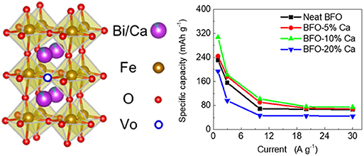
Graphical Abstract. Improving the intrinsic conductivity of perovskite BiFeO3 by doping with heterogeneous Ca2+ ions is an effective method for raising the electrochemical performance of energy storage devices.
Introduction
With the continuous consumption of non-renewable energy, renewable energy is constantly being explored by researchers. Solar energy, wind energy, tidal energy, etc., as valuable energy provided by nature to humans, are kinds of intermittent energy. To address this problem, energy storage devices have also been developed, such as lithium-ion batteries, sodium-ion batteries, aluminum-ion batteries, and supercapacitors (Kundu et al., 2015; Sun et al., 2015; Nayak et al., 2017; Ho and Lin, 2019). With the continuous development of science and technology, the requirements of 3C (Computers, Communication, and Consumer electronics) products for batteries are gradually increasing. Simultaneously, the energy storage equipment is required to have excellent performance, such as high energy density, small volume, and fast charge-discharge rates (Choi and Aurbach, 2016; Zhang et al., 2019).
Perovskite materials with a general formula of ABO3 are used in energy storage materials such as solar cells, lithium ion batteries, fuel cells, and supercapacitors (Mefford et al., 2014; Saliba et al., 2016; Zhang et al., 2016; Zhou et al., 2016). In the previous work, the B site was widely studied as an active site. However, there is a few electrochemical processes that are linked with the ions from the A site. In recent work, we have found that the A-site with the largest atomic radius of the perovskite BFO can also act as an electrochemically active site (Ma et al., 2019). The results indicate that A site with heterogeneous ion doping would be a new perspective for improving the electrochemical ability in energy storage.
The inherent conductivity of transition metal oxides is low, which restricts the rapid charge—discharge process for high-performance electrode materials (Xia and Alshareef, 2015; Lukatskaya et al., 2017). In order to solve this problem, various strategies have been proposed to improve conductivity of materials, such as using a conductive carbon-based composites (Wang et al., 2016a,b). The synergistic effects of hybrid materials are widely used to improve conductivity and electrochemical property of a single-phase material. In order to essentially enhance the conductivity of the material, a strategy of heterogeneous ion doping is proposed to increase the material conductivity. For instance, Park et al. reported that the electrical conductivity of the perovskite oxide Pr1−xSrxCoO3−δ for intermediate-temperature solid oxide fuel cells was enlarged with increasing strontium content (0.1 < x < 0.3). When the substitution amount x was >0.3, the conductivity of the material decreased. Thus, substitution of appropriate heterogeneous ions can improve the material conductivity. The electrochemical performance of Pr1−xSrxCoO3−δ//Ni-GDC cell demonstrates that the maximum power density at 973 K was 1.19 W cm−2 with x = 0.3 (Park et al., 2012). Li et al. found that a niobium and tantalum co-substituted perovskite SrCo0.8Nb0.1Ta0.1O3−δ exhibits high electroactivity. A symmetrical fuel cell consisting of SrCo0.8Nb0.1Ta0.1O3−δ positive electrode and Gd0.1Ce0.9O1.95 negative electrode has peak power densities of 1.2 Wcm−2 and 0.7 Wcm−2 at 500 and 450°C, respectively. The high performance is attributed to an optimal balance of oxygen vacancies (Li et al., 2017). The electrical conductivity of La0.5Ca0.5CoO3 was significantly increased and the specific capacitance reached 170 F g−1 at current density of 1 A g−1 (Mo et al., 2018).
As a typical ABO3 perovskite structure, bismuth ferrite also faces the problem of unexpected conductivity. The potential strategy is proposed to raise the intrinsic conductivity of BFO by ion doping. The introduction of oxygen vacancies can effectively improve material electronic transport capabilities. In this article, this strategy is used to enhance the conductivity of BFO through the doping of Ca2+ ions. By comparing the electrochemical performance of different Ca2+ ion doping amounts, it is found that 10% Ca2+ doping (BFO-10%Ca) can offer 305.5 mAh g−1 at 1 A g−1. The assembled BFO-10%Ca//graphene hybrid electrochemical energy storage devices exhibit excellent cycle stability at 5 A g−1 after 3,000 cycles.
Experimental Section
Materials
All the reagents were of analytical grade and were not purified prior to use. Bi(NO3)3·5H2O, Fe(NO3)3·9H2O, Ca(NO3)2·4H2O and ethylene glycol were bought from Shanghai Macklin Biochemical Co., Ltd, China. Graphene nanoplatelets were purchased from Strem Chemicals, Inc.
Synthesis of BFO and BFO-Ca
Synthesis of BFO was obtained by sol-gel method. The specific steps were as follows by three steps. In the first step, Bi(NO3)3·5H2O(5.822 g) and Fe(NO3)3·9H2O(4.040 g) were dissolved in a certain amount of ethylene glycol. This solution was stirred well and stirred at 50°C for 1 h. Then the temperature was raised to 90°C until the solvent was evaporated to obtain a dry gel. In the second step, the dry gel was treated at a high temperature for calcination to remove the solvent under air conditions. In the third step, the powder sample was once again calcined at 650°C to remove impurities and increase the crystal of BFO. Finally, the resulting BFO was washed with dilute nitric acid having a volume fraction of 10% and dried at 60°C for 12 h.
Three samples, BFO-x%Ca (x = 5, 10, and 20), were also synthesized in the same process at the mole ratio of 19:1, 9:1, and 8:2 between Bi(NO3)3·5H2O and Ca(NO3)3·4(H2O), respectively.
Fabrication of BFO and BFO-x%Ca Electrode
The electrode preparation process was prepared according to the following steps as follows. Specifically, the 80 wt% BFO, 10 wt% conductive carbon black and 10 wt% polytetrafluoroethylene (PTFE) were mixed to form a plasticine-like sheet and then pressed on the foamed nickel under a pressure of 5 MPa. The BFO-x%Ca (x = 5, 10, and 20) electrodes were fabricated according to the same method.
Three-Electrode System Electrochemical Measurements
In this experiment, the three-electrode system mainly consists of a working electrode, a reference electrode and a counter electrode. BFO and BFO-x%Ca (x = 5, 10, and 20) electrodes were used as working electrode, Hg/HgO electrode as reference electrode, and Pt foil as counter electrode. Electrochemical testing of electrodes was mainly completed in a three-electrode system, included cyclic voltammogram (CV), galvanostatic charge-discharge (GCD) and electrochemical impedance spectroscopy (EIS) by using a Biologic VMP3 electrochemical workstation in 6 mol L−1 KOH aqueous electrolyte. All the electrochemical testing procedures were performed at room temperature. The frequency range of EIS is set at 10−2-105 HZ.
Two-Electrode HEESDs
HEESDs were assembled with BFO-10%Ca as the positive electrode and graphene as the negative electrode. A cellulose separator was used as the separator to prevent direct contact between the positive and negative electrodes. In the two-electrode system, the positive and negative electrodes remain electrically neutral and should satisfy the relationship Q+ = Q−.
Material Characterizations
X-ray diffraction (XRD) testing of BFO and BFO-x% samples was performed by the Bruker D8 Advance (Germany) diffractometer operating in the reflection mode with Cu-Ka radiation. The angle range of 2 theta was set in the range of 15–90° at scan speed 2° min−1. The morphological analysis of the samples was performed using a field-emission scanning electron microscope (FESEM, S4800, Hitachi, Japan) and transmittance electron microscope (TEM) (Tecnai G2 F30, FEI, America). The TEM samples were prepared as follows. Firstly, ~1.5 mg of the sample, which was cleaned and dried in advance, was placed in a glass bottle. Then, 5–8 ml of absolute ethanol was added to the glass bottle and dispersed by ultra-sonication for 10 min. Finally, the uniform solution was dropped on a 300-mesh copper grid with a pipette to dry naturally at room temperature. X-ray photoelectron spectroscopy (XPS) was examined using an ESCALAB 250Xi instrument (Thermo Fisher Scientific).
Results and Discussion
A single-phase perovskite structure of BiFeO3 was synthesized by sol-gel method. As presented in Figures 1A,C, the XRD patterns of BFO are well consistent with the standard value reported in JCPDS card (no. 86-1518), which reveals the presence of a rhombohedral crystal structure (R3c space group). After calcium ions doping into BiFeO3, the single-phase BiFeO3 (R3c space group) gradually transforms into a new phase (P4mm space group), which is mainly attributed to the change of Bi-O bond and the Ca-O bond after the Bi3+ ions were partially replaced by the Ca2+ ions (Figure 1B). Ca2+ ion-doped BFO crystal structure introduces oxygen vacancies due to the substitution of divalent Ca2+ ions for trivalent Bi3+ ions. At the same time, the introduction of oxygen vacancies can improve the conductivity of the material. The XRD results of BFO and different Ca2+ ion doped BFO samples are shown in Figure 1C. The XRD of BFO is in good agreement with the standard spectrum JCPDS card (no. 86-1518), while the XRD patterns of three samples, BFO-5%Ca, BFO-10%Ca, and BFO-20%Ca, exhibit little difference in position and intensity from the shape. The partially magnified patterns at 2 theta (~32°) show that the diffraction peak shifted toward a higher angle with the increase of the doping amount of Ca2+ ions (Figure 1D). The lattice parameters (a and c) of the R3c phase decrease with increasing doping level (Figure 1D), which causes the structure of BFO distorts or changes from rhombohedral to tetragonal phase.
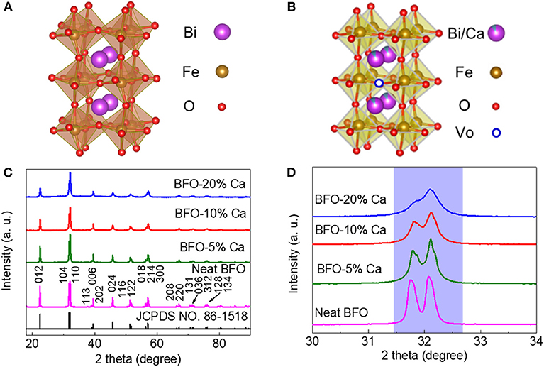
Figure 1. (A,B) Schematic diagram of the crystal structure of BFO and BFO-Ca; (C) XRD pattern of different Ca2+ ion doping; (D) Partial enlargement of the 2 theta (~32°) of BFO, BFO-5%Ca, BFO-10%Ca, and BFO-20%Ca.
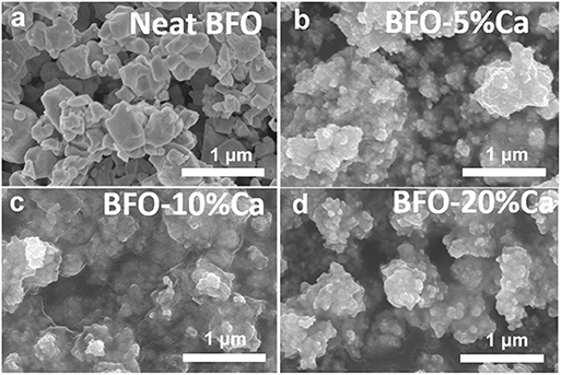
In order to compare the differences in the morphology of pure BFO and Ca2+ ion doped BFO samples, SEM was used to characterize the morphology of the particles. Figure 2a shows the SEM image of pure BFO. It can be seen that the size of BFO particles is different, and mainly distributed in the range of ~400–700 nm. As displayed in Figures 2b–d, the particle size of three samples (BFO-5%Ca, BFO-10%Ca, and BFO-20%Ca) is significantly smaller than that of the pure BFO, which exhibits a typical feature of nanoparticle cluster. The introduction of Ca2+ ions into BFO has a great influence on the size of the particles due to the smaller crystal unit cell volume of the tetragonal phase. The SEM images exhibit that the surface of the BFO sample after Ca2+ doping is smoother than that of pure BFO. This can be attributed to small nucleation cores aggregating together into big grains (Costa et al., 2014).
HRTEM was utilized to characterize the microstructure of the neat BFO, BFO-5%Ca, BFO-10%Ca, and BFO-20%Ca samples, as shown in Figures 3a–d. In particular, the spacing of the adjacent lattice fringes in the neat BFO is about 0.284 and 0.399 nm (Figure 3a), in accordance with the (104) and (012) planes of pure BFO (Li et al., 2016). The TEM images of high-resolution images along [110] zone axis are shown to confirm small changes in the crystal structure (Figures 3e–h) (Gao et al., 2018). As shown in the inset, the coexistence of rhombohedral and tetragonal phases in the calcium ion doped BFO samples are also found by the fast Fourier transform (FFT). The results of selected area electron diffraction (SAED) pattern show good single-crystal characteristics for pure BFO. The presence of 1/2{ooo} superlattice spots confirms the rhombohedral phase BFO using SAED pattern along the [110] zone axis direction (Figure 3i) (Cheng et al., 2009; Liu et al., 2018; Wang et al., 2018). This corresponds to the standard XRD card and demonstrates that a pure phase BFO sample can be obtained by sol-gel method (Figure 1C). Figures 3j–l shows that the new tetragonal phase is found in the BFO-5%Ca, BFO-10%Ca, and BFO-20%Ca three samples. 1/2{ooo} superlattice spots disappear gradually with increasing amount of calcium ions. This is attributed to the changes of value of c/a, when the Bi3+ ions are partially replaced by Ca2+ ions. The spacing of the adjacent lattice fringes is 0.279, 0.284, 0.296, and 0.396 nm in the BFO-5%Ca BFO-10%Ca and BFO-20%Ca responds to the [110], (104), and (012) crystal plane of rhombohedral BFO, [110] crystal plane of tetragonal phase BFO, respectively (Zeches et al., 2009; Han et al., 2016; Li et al., 2016). The tilt of the same plane for the two phases is about 3.8°, in agreement with the existence of two phases (Figure 3l) (Cheng et al., 2009; Guo et al., 2017).
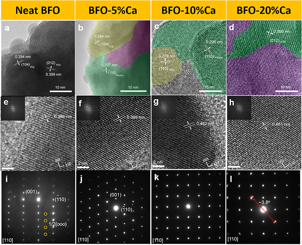
Figure 3. HRTEM images of (a–h) neat BFO and BFO with different doping amounts of Ca2+ ions (inset: FFT patterns); (i–l) SAED patterns along the [110] zone axis direction.
The chemical bonds of the elements can be monitored in BFO samples and three different Ca2+ ion doped BFO samples were used to track the valence state of each element by XPS spectrum analysis, as displayed in Figure 4. The wide XPS survey spectrum of the BFO samples with different calcium ion doping amounts is shown in Figure S1. As illustrated, the narrow-scan Bi4f spectrum of the neat BFO reveals two peaks located at 158.7 and 164.0 eV (Figure 4A), identified as Bi4f 7/2 and Bi4f 5/2, respectively. As reported in previous literature, this can be identified as Bi3+ (Bai et al., 2019). The bonding energy of the element Bi4f was shifted to the lower angle with increasing the amount of doped Ca2+ ions, because the introduction of Ca2+ ions changes the chemical environment around the Bi3+ ions. At the same time, this further proves that the change of Ca-O bond and Bi-O bond length formed by Ca2+ ions (radius: 1.12 Å) partially instead of Bi3+ ions (radius: 1.17 Å) causes structural change. For the Ca2p spectrum, the main Ca2p peaks were situated at 346.3 and 349.8eV (Figure 4B), corresponding to Ca2p3/2 and Ca2p1/2, respectively. This is one typical characteristic and demonstrate that Ca2+ ions were doped into BFO samples (Zhang et al., 2018). As an approximately quantitative analysis, the increased integrated area of the calcium 2p peak indicates that the content of calcium ions in the doped BFO sample gradually increases (Zhao et al., 2007; Wang et al., 2019). The difference electronegativity values of Ca and Bi elements results in slight shift of Bi4f peaks toward the lower binding energy side with increasing Ca2+ content in BFO samples. In this case, the Fe2p spectrum also shows different valence changes due to the surrounding environment changing. In the track of elemental Fe, two typical Fe2p 1/2 and Fe2p 3/2 peaks could be observed, at 724.6 and 710.8 eV, respectively. The Fe2p spectrum reveals one satellite peaks (“sat.”) at 718 eV, which is the characteristic peak of Fe3+, as reported in the literature (Ma et al., 2013). The Fe2p1/2 and Fe2p3/2 peaks split into two peaks with the introduction of Ca2+ ions. At the same time, the peaks appeared at 725.6, 723.4, 712.0, and 710.0 eV, which also indicates that Fe3+ and Fe2+ ions coexist in calcium-doped BFO samples (Ye et al., 2017; Spivakov et al., 2019). The formation of tetragonal BFO is accompanied by transformation of the FeO6 octahedra into FeO5 pyramids (Rossell et al., 2012). Thus, divalent and three irons coexist in three samples doped with Ca2+ ions. The high-resolution O1s spectrum can feed back the information including oxygen-metal bonding and oxygen vacancies. O1s spectra can be separated into three peaks three peaks at 529.3, 530.6, and 532.6 eV, which correspond to Fe-O, Bi-O bonds, and the surface-adsorbed water (Soltani and Lee, 2016; Gu et al., 2019). The bond energy was shifted from 530.6 to 530.2 eV, which indicates the presence of oxygen vacancies with different doping amounts of Ca2+ ions (Ibrahim et al., 2007; Jaafar et al., 2019). The formation of these oxygen vacancy defects may be attributed the Ca2+ ion substitution at Bi3+ ions of BFO to maintain charge neutrality (Ramachandran et al., 2012).
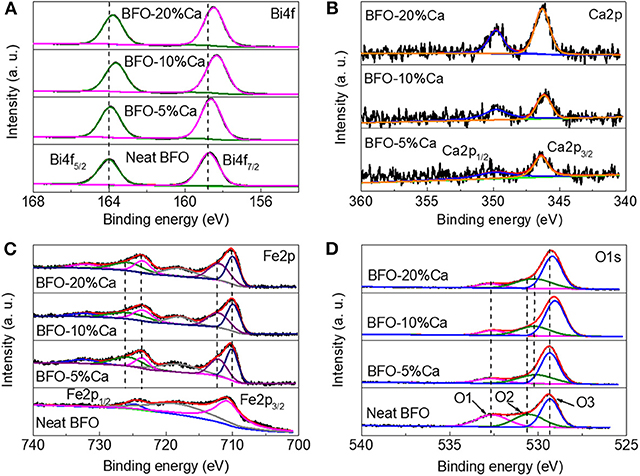
Figure 4. XPS spectra of BFO, BFO-5%Ca, BFO-10%Ca, and BFO-20%Ca, (A) Bi4f peak, (B) Ca2p peak, (C) Fe2p peak, and (D) O1s peak.
A three-electrode system was used to accurately characterize the electrochemical properties of the materials. Figure 5A displays the CV of BFO at various scan rates. A pair of obvious redox peaks exhibited in the CV diagram, which is mainly attributed to the redox reaction of Bi3+ ions located at the A site of the perovskite structure at different potentials. Due to the unexpected conductivity of pure BFO, the BFO (the inside electron conductance) does not match well with the external ions as the current increased, which will cause the distortion of the CV curves (Figure 5A). In order to improve the conductivity of the BFO material, calcium ions partially replace the Bi3+ ions to form more oxygen vacancies to improve the conductivity of the neat material (Mo et al., 2018). By measuring the electrochemical properties of different Ca2+ doping amounts, a suitable degree of substitution is finally selected. By comparing the CV plots of the different amounts of Ca2+ ion doping, it can be found that the degree of distortion in the CV curves is gradually reduced at the scanning rate 2, 5, 10, 20, 40, and 60 mV s−1 and finally the 10% calcium-doped BFO is determined to be a suitable degree of substitution (Figures 5B–D). This also shows that doping of heterogeneous ions is an effective way to improve the electrical conductivity of materials.
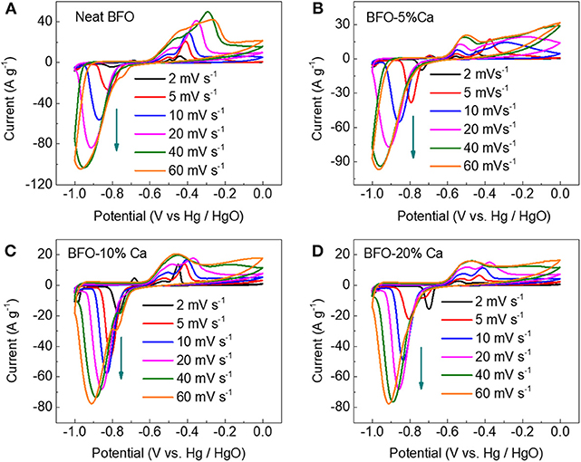
Figure 5. CV plots of (A) the neat BFO, (B) BFO-5%Ca, (C) BFO-10%Ca, and (D) BFO-20%Ca at various scan rates.
Testing of the electrode material was completed through a three-electrode test system. Figure 6A shows a neat BFO charge—discharge curves. The charge—discharge test line does not exhibit good symmetry due to the poor conductivity of the material. However, the charge—discharge curves of Ca2+ ion doped samples with different doping levels are almost symmetrical, indicating that these materials have good reversible capacity and excellent coulombic efficiency (Figures 6B–D). The charge-discharge diagrams of pure BFO and calcium-doped BFO samples can also correspond to the cyclic voltammogram obtained at different scan rates (Figure 5). The specific capacity calculated at different current densities is shown in Figure 6E. Comparing different doping amounts of Ca2+ ions, 10% of the samples (BFO-10%Ca) shows the best specific capacity 305.5, 182.0, 102.1, 76.2, and 74.8 mAh g−1 at diverse discharge current densities of 1, 3, 10, 20, and 30 A g−1, respectively. The performance improvement of BFO-10%Ca is mainly attributed to the better electrical conductivity with appropriate increasing calcium content and on the other hand the improved performance of calcium-modified BFO is higher than the capacity loss in the samples substituted by Ca2+ ions. This energy storage mechanism of BFO with different doping amount of Ca2+ ions can be expressed by the following equation (Ma et al., 2019):
The electrochemical impedance spectroscopy (EIS) spectra of pristine BFO, BFO-5%Ca, BFO-10%Ca, and BFO-20%Ca are shown in Figure 6F. In contrast to the neat BFO sample, three samples of Ca2+ ion doped electrodes shows smaller semicircle diameter, manifesting a lower electron transfer resistance at the electrode interface and higher electrochemical conductivity after the introduction of Ca2+ ions. Noticeably, the results of the ohmic impedance at higher frequency suggest that the values were measured to be 0.95, 1.02, and 1.06 Ohm in the BFO-5%Ca, BFO-10%Ca, and BFO-20%Ca, respectively. These values are apparently lower than that of the pristine BFO (1.17 Ohm), which also indicates that the doping strategy could reduce the ohmic impedance, favorable for boosting the charge and discharge capabilities.
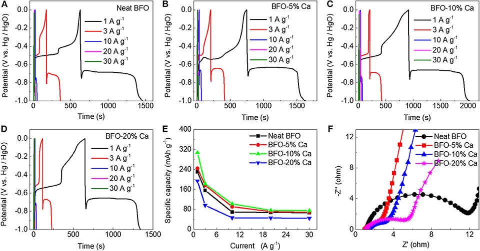
Figure 6. Electrochemical properties of the BFO, BFO-5%Ca, BFO-10%Ca, and BFO-20%Ca powders in a three-electrode system. (A–D) Charge-discharge curves of the four samples at various current densities; (E) the specific capacitance at various current densities; (F) Comparison of EIS curves of BFO, BFO-5%Ca, BFO-10%Ca, and BFO-20%Ca.
Calcium ions were doped at the A site in the BFO samples. The trivalent Bi3+ ions were replaced by the bivalent Ca2+ ions, which will cause the uneven charge distribution. Such doping effect would compensate Ca2+ ion acceptors in terms of generating oxygen vacancies as donor impurities (Masó and West, 2012). This conductor-insulator transition can be accepted in terms of the competition between a mobility edge and the Fermi energy through band-filling control. In a proper amount of calcium ion-doped BFO samples, the conductivity of the doped samples is enhanced by band filling (Park et al., 2012; Yang et al., 2012).
Assembled Hybrid Electrochemical Energy Storage Devices (HEESDs)
Figure 7 shows the electrochemical performance test using the three electrodes and two electrodes. A HEESD consists of BFO-10%Ca as the positive electrode and commercial graphene as the negative electrode. The cyclic voltammogram is obtained through a three-electrode system, which shows a rectangle with increasing scan rate. In order to characterize the electrochemical storage capacity of the graphene, a galvanostatic charge-discharge test was performed through a three-electrode system with graphene as the working electrode. This figure shows an isosceles triangle shape, indicating that graphene stores charges by means of an electric double layer (Figure 7B). The specific capacitances were 99.2, 74.6, 68.4, 60.8, 55.8, and 52 mAh g−1 at 1, 3, 5,10, 15, and 20 A g−1 (Figure 7C), respectively.
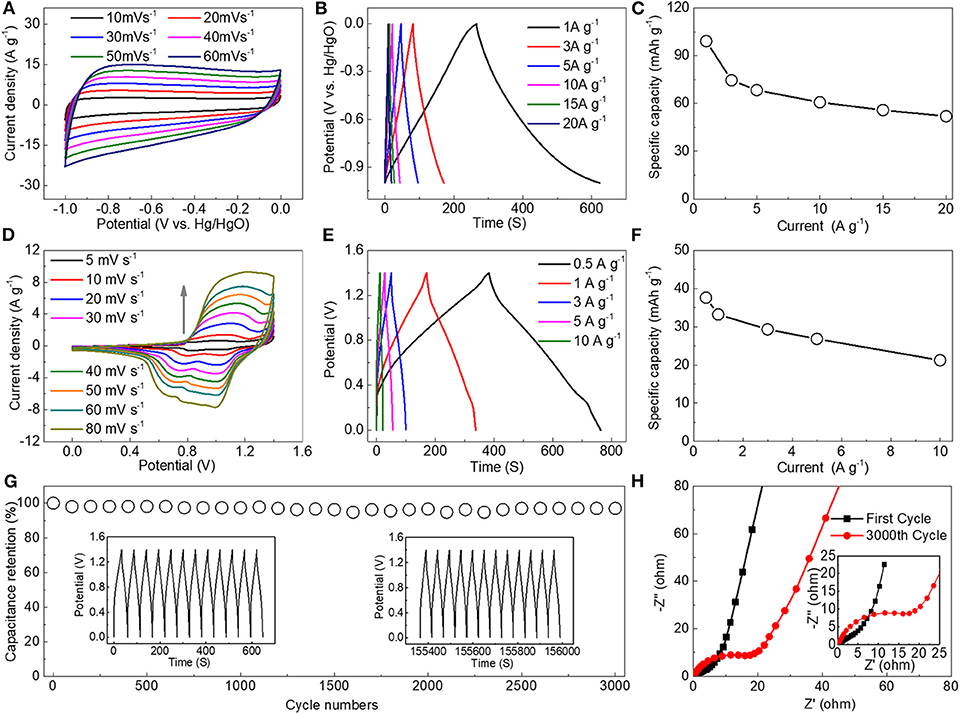
Figure 7. Electrochemical properties of HEESDs: (A) CV and (B) charge-discharge curves of the commercial graphene electrode at various scan rates and current densities; (C) Specific capacity at different current densities under a three-electrode test system with the commercial graphene; (D) CV and (E) charge-discharge curves of the BFO-10%Ca//commercial graphene HEESDs at various scan rates and current densities; (F) The relationship between current density and capacity; (G) Cycling performance of the HEESDs at a current density of 5 A g−1; (H) EIS comparison curves of the HEESDs for the first cycle and 3,000th cycle.
The HEESDs were fabricated using the BFO-10%Ca as the positive electrode and the graphene as the negative electrode. Electrochemical performance testing of the HEESDs was achieved using a two-electrode test system. The voltage range of 0–1.4 V was selected in accordance with the absence of polarization in the 6 mol L−1 KOH aqueous solution by test results of CV plots at various potential windows (Figure S2). The CV diagram shows two typical electrochemical storage mechanisms, that is, the electric double layer characteristics in the 0–0.5 V voltage range and the Faraday reaction in the 0.5–1.4 V range. The discharge curve of the HEESDs is almost symmetrical with the charging curve, showing an isosceles triangle, as exhibited in Figure 7E. The specific capacity at different current densities can be obtained by calculation of the discharge curve. The specific capacitances were calculated to be 37.7 and 21.3 mAh g−1 at 0.5 and 20 A g−1 (Figure 7F), respectively. Cyclic performance, as an important performance indicator, was performed through 3,000 consecutive charge—discharge tests. The assembled HEESDs exhibited excellent cycle stability at 5 Ag−1 after 3,000 cycles. Compared to the capacity after 3,000 cycles, very limited capacity loss was observed, showing that the assembled HEESDs presented good reversible capacity (Figure 7G). The capacity fading is related with carrier concentration loss and internal impedance growth in the HEESDs. This is mainly due to the charge transfer and diffusion resistances, caused by the formation of new phases after repeated charge and discharge cycles of BFO-10% Ca. It can be also proved by comparing the change of EIS diagrams before and after the different cycle numbers (Schmitt et al., 2017; Upadhyay et al., 2017; Yu et al., 2018). The EIS spectra of the HEESDs were shown in Figure 7H. The Nyquist diagram clearly includes the arc in the high frequency region and the straight line in the low frequency region. After 3,000 cycles, the semi-circular arc is larger in the high frequency region, indicating that the charge transfer resistance was significantly larger than that of the first cycle (Xu et al., 2017), which is in a good response to the decay of performance after multiple cycles.
Conclusions
In summary, the electrical conductivity is enhanced by introducing oxygen vacancies via partial replacement of Bi3+ ions by Ca2+ ions in the BFO perovskite materials. By tuning the doping amount, the electrochemical performance of BFO-10%Ca was significantly improved. The HEESDs were fabricated using the BFO-10%Ca as the positive electrode and the commercial graphene as the negative electrode, showing excellent cycle stability at 5 Ag−1 after 3,000 cycles. The strategy by improving the intrinsic conductivity of materials by doping with heterogeneous ions is an effective method for improving the electrochemical performance of energy storage devices.
Data Availability Statement
All datasets generated for this study are included in the article/Supplementary Material.
Author Contributions
NL conceived and supervised the project. C-JM performed the experiment, characterized the materials, and wrote the manuscript supervised. All the authors discussed the results of the paper. W-LS helps correct grammatical errors.
Funding
Financial support from Beijing Natural Science Foundation (Grant No. 2182065) and National Natural Science Foundation of China (Grant No. 11672341) was gratefully acknowledged.
Conflict of Interest
The authors declare that the research was conducted in the absence of any commercial or financial relationships that could be construed as a potential conflict of interest.
Supplementary Material
The Supplementary Material for this article can be found online at: https://www.frontiersin.org/articles/10.3389/fmats.2020.00015/full#supplementary-material
References
Bai, X., Ji, M., Xu, M., Su, N., Zhang, J., Wang, J., et al. (2019). Synthesis of M-doped (M = Ag, Cu, In) Bi2Te3 nanoplates via a solvothermal method and cation exchange reaction. Inorg. Chem. Front. 6, 1097–1102. doi: 10.1039/C9QI00116F
Cheng, C.-J., Kan, D., Lim, S.-H., McKenzie, W. R., Munroe, P. R., Salamanca-Riba, L. G., et al. (2009). Structural transitions and complex domain structures across a ferroelectric-to-antiferroelectric phase boundary in epitaxial Sm-doped BiFeO3 thin films. Phys. Rev. B 80:014109. doi: 10.1103/PhysRevB.80.014109
Choi, J. W., and Aurbach, D. (2016). Promise and reality of post-lithium-ion batteries with high energy densities. Nat. Rev. Mater. 1:16013. doi: 10.1038/natrevmats.2016.13
Costa, L. V., Deus, R. C., Foschini, C. R., Longo, E., Cilense, M., and Simões, A. Z. (2014). Experimental evidence of enhanced ferroelectricity in Ca doped BiFeO3. Mater. Chem. Phys. 144, 476–483. doi: 10.1016/j.matchemphys.2014.01.022
Gao, M., Viswan, R., Tang, X., Leung, C. M., Li, J., and Viehland, D. (2018). Magnetoelectricity of CoFe2O4 and tetragonal phase BiFeO3 nanocomposites prepared by pulsed laser deposition. Sci. Rep. 8:323. doi: 10.1038/s41598-017-18788-8
Gu, X., Jing, H., Mu, X., Yang, H., Zhou, Q., Yan, S., et al. (2019). La-triggered synthesis of oxygen vacancy-modified cobalt oxide nanosheets for highly efficient oxygen evolution in alkaline media. J. Alloys. Compd. 814:152274. doi: 10.1016/j.jallcom.2019.152274
Guo, Y., Liu, Y., Qi, Y., Wang, J., Liang, K., and Zhang, T. (2017). Microstructure and temperature stability of highly strained tetragonal-like BiFeO3 thin films. Appl. Surf. Sci. 425, 117–120. doi: 10.1016/j.apsusc.2017.06.287
Han, Y. L., Liu, W. F., Wu, P., Xu, X. L., Guo, M. C., Rao, G. H., et al. (2016). Effect of aliovalent Pd substitution on multiferroic properties in BiFeO3 nanoparticles. J. Alloys. Compd. 661, 115–121. doi: 10.1016/j.jallcom.2015.11.157
Ho, K.-C., and Lin, L.-Y. (2019). A review of electrode materials based on core–shell nanostructures for electrochemical supercapacitors. J. Mater. Chem. A 7, 3516–3530. doi: 10.1039/C8TA11599K
Ibrahim, Z., Othaman, Z., Karim, M. M. A., and Holland, D. (2007). X-ray photoemission spectroscopy (XPS) analysis on platinum doped stannic oxide ceramic. Solid State Sci. Technol. 15, 65–73. Available online at: http://jss.ecsdl.org/content/by/year
Jaafar, N. F., Najman, A. M. M., Marfur, A., and Jusoh, N. W. C. (2019). Strategies for the formation of oxygen vacancies in zinc oxide nanoparticles used for photocatalytic degradation of phenol under visible light irradiation. J. Photoch. Photobio. A 388:112202. doi: 10.1016/j.jphotochem.2019.112202
Kundu, D., Talaie, E., Duffort, V., and Nazar, L. F. (2015). The emerging chemistry of sodium ion batteries for electrochemical energy storage. Angew. Chem. Int. Ed. 54, 2–20. doi: 10.1002/anie.201410376
Li, M., Zhao, M., Li, F., Zhou, W., Peterson, V. K., Xu, X., et al. (2017). A niobium and tantalum co-doped perovskite cathode for solid oxide fuel cells operating below 500 °C. Nat. Commun. 8:13990. doi: 10.1038/ncomms13990
Li, Z.-J., Hou, Z.-L., Song, W.-L., Liu, X.-D., Cao, W.-Q., Shao, X.-H., et al. (2016). Unusual continuous dual absorption peaks in Ca-doped BiFeO3 nanostructures for broadened microwave absorption. Nanoscale 8, 10415–10424. doi: 10.1039/C6NR00223D
Liu, N., Liang, R., Zhang, G., Zhou, Z., Yan, S., Li, X., et al. (2018). Colossal negative electrocaloric effects in lead-free bismuth ferrite-based bulk ferroelectric perovskite for solid-state refrigeration. J. Mater. Chem. C 6, 10415–10421. doi: 10.1039/C8TC04125C
Lukatskaya, M. R., Kota, S., Lin, Z., Zhao, M.-Q., Shpigel, N., Levi, M. D., et al. (2017). Ultra-high-rate pseudocapacitive energy storage in two-dimensional transition metal carbides. Nat. Energy 2:17105. doi: 10.1038/nenergy.2017.105
Ma, C.-J., Chen, Y., Zhu, C., Chen, Q., Song, W.-L., Jiao, S., et al. (2019). Bismuth ferrite: an abnormal perovskite with electrochemical extraction of ions from A site. J. Mater. Chem. A 7, 12176–12190. doi: 10.1039/C9TA02569C
Ma, Y., Fang, C., Ding, B., Ji, G., and Lee, J. Y. (2013). Fe-doped MnxOy with hierarchical porosity as a high-performance lithium-ion battery anode. Adv. Mater. 25, 4646–4652. doi: 10.1002/adma.201301906
Masó, N., and West, A. R. (2012). Electrical properties of Ca-doped BiFeO3 ceramics: from p-type semiconduction to oxide-Ion conduction. Chem. Mater. 24, 2127–2132. doi: 10.1021/cm300683e
Mefford, J. T., Hardin, W. G., Dai, S., Johnston, K. P., and Stevenson, K. J. (2014). Anion charge storage through oxygen intercalation in LaMnO3 perovskite pseudocapacitor electrodes. Nat. Mater. 13, 726–732. doi: 10.1038/nmat4000
Mo, H., Nan, H., Lang, X., Liu, S., Qiao, L., Hu, X., et al. (2018). Influence of calcium doping on performance of LaMnO3 supercapacitors. Ceram. Int. 44, 9733–9741. doi: 10.1016/j.ceramint.2018.02.205
Nayak, P. K., Erickson, E. M., Schipper, F., Penki, T. R., Munichandraiah, N., Adelhelm, P., et al. (2017). Review on challenges and recent advances in the electrochemical performance of high capacity Li- and Mn-rich cathode materials for Li-ion batteries. Adv. Energy Mater. 8:1702397. doi: 10.1002/aenm.201702397
Park, S., Choi, S., Shin, J., and Kim, G. (2012). lectrochemical investigation of strontium doping effect on high performance Pr1−xSrxCoO3−δ (x = 0.1, 0.3, 0.5, and 0.7) cathode for intermediate-temperature. J. Power Sources 210, 172–177. doi: 10.1016/j.jpowsour.2012.03.018
Ramachandran, B., Dixit, A., Naik, R., Lawes, G., and Ramachandra Rao, M. S. (2012). Weak ferromagnetic ordering in Ca doped polycrystalline BiFeO3. J. Appl. Phys. 111:023910. doi: 10.1063/1.3678449
Rossell, M. D., Erni, R., Prange, M. P., Idrobo, J.-C., Luo, W., Zeches, R. J., et al. (2012). Atomic structure of highly strained BiFeO3 thin films. Phys. Rev. Lett. 108:047601. doi: 10.1103/PhysRevLett.108.047601
Saliba, M., Matsui, T., Domanski, K., Seo, J.-Y., Ummadisingu, A., Zakeeruddin, S. M., et al. (2016). Incorporation of rubidium cations into perovskite solar cells improves photovoltaic performance. Science 354, 206–209. doi: 10.1126/science.aah5557
Schmitt, J., Maheshwari, A., Heck, M., Lux, S., and Vetter, M. (2017). Impedance change and capacity fade of lithium nickel manganese cobalt oxide-based batteries during calendar aging. J. Power Sources 353, 183–194. doi: 10.1016/j.jpowsour.2017.03.090
Soltani, T., and Lee, B.-K. (2016). Sono-synthesis of nanocrystallized BiFeO3 /reduced graphene oxide composites for visible photocatalytic degradation improvement of bisphenol A. Chem. Eng. J. 306, 204–213. doi: 10.1016/j.cej.2016.07.051
Spivakov, A. A., Lin, C.-R., Jhang, C.-J., Tsai, Y.-J., and Tseng, Y.-T. (2019). Synthesis and characterization of carbon-coated wustite nanoparticles. Mater. Lett. 249, 147–150. doi: 10.1016/j.matlet.2019.04.070
Sun, H., Wang, W., Yu, Z., Yuan, Y., Wang, S., and Jiao, S. (2015). A new aluminium-ion battery with high voltage, high safety and low cost. Chem. Commun. 51, 11892–11895. doi: 10.1039/C5CC00542F
Upadhyay, K. K., Nguyen, T., Silva, T. M., Carmezim, M. J., and Montemor, M. F. (2017). Electrodeposited MoOx films as negative electrode materials for redox supercapacitors. Electrochim. Acta 225, 19–28. doi: 10.1016/j.electacta.2016.12.106
Wang, D., Fan, Z., Zhou, D., Khesro, A., Murakami, S., Feteira, A., et al. (2018). Bismuth ferrite-based lead-free ceramics and multilayers with high recoverable energy density. J. Mater. Chem. A 6, 4133–4144. doi: 10.1039/C7TA09857J
Wang, S., Jiao, S., Wang, J., Chen, H.-S., Tian, D., Lei, H., et al. (2016b). High-performance aluminum-ion battery with CuS@C microsphere composite cathode. ACS Nano 11, 469–477. doi: 10.1021/acsnano.6b06446
Wang, S., Yu, Z., Tu, J., Wang, J., Tian, D., Liu, Y., et al. (2016a). A Novel Aluminum-ion battery: Al/AlCl3-[EMIm]Cl/Ni3S2@graphene. Adv. Energy Mater. 6:1600137. doi: 10.1002/aenm.201600137
Wang, Z., Xie, Y., Lei, Z., Lu, Y., Wei, G., Liu, S., et al. (2019). Quantitative analysis of surface sites on carbon dots and their interaction with metal ions by potentiometric titration method. Anal. Chem. 91, 9690–9697. doi: 10.1021/acs.analchem.9b01225
Xia, C., and Alshareef, H. N. (2015). Self-templating scheme for the synthesis of nanostructured transition-metal chalcogenide electrodes for capacitive energy storage. Chem. Mater. 27, 4661–4668. doi: 10.1021/acs.chemmater.5b01128
Xu, J., Ma, C., Cao, J., and Chen, Z. (2017). Facile synthesis of core–shell nanostructured hollow carbon nanospheres@nickel cobalt double hydroxides as high-performance electrode materials for supercapacitors. Dalton Trans. 46, 3276–3283. doi: 10.1039/C6DT04759A
Yang, C.-H., Kan, D., Takeuchi, I., Nagarajan, V., and Seidel, J. (2012). Doping BiFeO3: approaches and enhanced functionality. Phys. Chem. Chem. Phys. 14, 15953–15962. doi: 10.1039/c2cp43082g
Ye, Y.-J., Zhang, N., and Liu, X.-X. (2017). Amorphous NiFe(oxy)hydroxide nanosheet integrated partially exfoliated graphite foil for high efficiency oxygen evolution reaction. J. Mater. Chem. A 5, 24208–24216. doi: 10.1039/C7TA06906E
Yu, Z., Jiao, S., Li, S., Chen, X., Song, W.-L., Teng, T., et al. (2018). Flexible stable solid-state Al-ion batteries. Adv. Funct. Mater. 29:1806799. doi: 10.1002/adfm.201806799
Zeches, R. J., Rossell, M. D., Zhang, J. X., Hatt, A. J., He, Q., Yang, C.-H., et al. (2009). A strain-driven morphotropic phase boundary in BiFeO3. Science 326, 977–980. doi: 10.1126/science.1177046
Zhang, H., Chen, H., Azat, S., Mansurov, Z. A., Liu, X., Wang, J., et al. (2018). Super adsorption capability of rhombic dodecahedral Ca-Al layered double oxides for Congo red removal. J. Alloys Compd. 768, 572–581. doi: 10.1016/j.jallcom.2018.07.241
Zhang, W., Eperon, G. E., and Snaith, H. J. (2016). Metal halide perovskites for energy applications. Nat. Energy 1:16048. doi: 10.1038/nenergy.2016.48
Zhang, X., Jiao, S., Tu, J., Song, W.-L., Xiao, X., Li, S., et al. (2019). Rechargeable ultrahigh-capacity tellurium-aluminum batteries. Energy Environ. Sci. 12, 1918–1927. doi: 10.1039/C9EE00862D
Zhao, K., Li, J., Wang, H., Zhuang, J., and Yang, W. (2007). Stoichiometric ratio dependent photoluminescence quantum yields of the thiol capping CdTe nanocrystals. J. Phys. Chem. C 111, 5618–5621. doi: 10.1021/jp0685636
Keywords: perovskite ceramic, BiFeO3, Ca ion doping, electrochemical performance, conductivity, rate capability
Citation: Ma C-J, Li N and Song W-L (2020) Tailoring the Electrochemical Behaviors of Bismuth Ferrite Using Ca Ion Doping. Front. Mater. 7:15. doi: 10.3389/fmats.2020.00015
Received: 08 December 2019; Accepted: 14 January 2020;
Published: 31 January 2020.
Edited by:
Dawei Wang, University of Sheffield, United KingdomReviewed by:
Weigang Yang, University of California, Santa Cruz, United StatesZhongming Fan, Pennsylvania State University (PSU), United States
Copyright © 2020 Ma, Li and Song. This is an open-access article distributed under the terms of the Creative Commons Attribution License (CC BY). The use, distribution or reproduction in other forums is permitted, provided the original author(s) and the copyright owner(s) are credited and that the original publication in this journal is cited, in accordance with accepted academic practice. No use, distribution or reproduction is permitted which does not comply with these terms.
*Correspondence: Na Li, MzEyMDE4NTU1MEBiaXQuZWR1LmNu
 Chao-Jie Ma1,2,3
 Wei-Li Song