 Vinicius de M. Schiefferdecker
 Guilherme M. O. Barra
 Silvia D. A. S. Ramôa
 Claudia Merlini
94% of researchers rate our articles as excellent or good
Learn more about the work of our research integrity team to safeguard the quality of each article we publish.
Find out more
ORIGINAL RESEARCH article
Front. Mater., 13 August 2019
Sec. Polymeric and Composite Materials
Volume 6 - 2019 | https://doi.org/10.3389/fmats.2019.00193
This article is part of the Research TopicRecent Advances in Intrinsically Conducting Polymers and CompositesView all 12 articles
In this work, non-woven mats of poly(vinylidene fluoride; PVDF) containing different weight fractions (2.5, 5, 10, and 12.5 wt%) of a nanostructured conductive additive based on montmorillonite—dodecylbenzenesulfonic acid—doped polypyrrole (Mt-PPy.DBSA) have been prepared by electrospinning. The effect of Mt-PPy.DBSA content on the properties of PVDF solution, mats morphology, thermo-mechanical, and electrical properties was investigated. Polymorphism of PVDF/Mt-PPy.DBSA mats was investigated by Fourier Transform Infrared (FTIR) spectroscopy. Moreover, the electromagnetic interference shielding effectiveness (EMI SE) and EMI attenuation mechanism was investigated. In order to perform a comparative study, nanocomposites with the same weight fraction of Mt-PPy.DBSA was also prepared by solution casting. The PVDF/Mt-PPy.DBSA mats display fibers with smaller diameters than neat PVDF, due to the increment in the ionic conductivity of the solution. The incorporation of the Mt-PPy.DBSA additive slightly improved electrical conductivity of the mats and they behave like as an electrically insulating material (10−14 S cm−1), due to their porosity, that prevents the formation of a conducting network. Furthermore, the EMI SE of electrospun mats is practically null, indicating that they are almost transparent to magnetic waves. On the other hand, nanocomposites fabricated by solution casting display superior electrical conductivity (10−2 S cm−1) and EMI SE reached values of −5 dB.
There is a strong scientific and technological interest for producing conductive polymer composites (CPC's) due to the wide design flexibility and properties that can be obtained by combining different materials. Moreover, CPC's can display both the advantages of organic polymers, such as lightweight, flexible and easily moldable, and functionality of conductive additives, especially the electrical conductivity (Kim et al., 2003; Das et al., 2009; Lakshmi et al., 2009; Pirvu et al., 2011; Qin and Brosseau, 2012; Yan et al., 2012; Luzio et al., 2014; Merlini et al., 2017; Ramoa et al., 2018; Ram et al., 2019).
Intrinsically conducting polymers (ICP's), such as polypyrrole (PPy) and polyaniline (PANI), have been used as conductive filler to produce CPC's (Moučka et al., 2011; Jin et al., 2016; Merlini et al., 2017; Ramoa et al., 2018). Considerable efforts have been made in order to improve the dispersion of ICP's into the matrix and to reduce the amount of the filler necessary to achieve high values of electrical conductivity. Works in literature have reported that the synthesis of PPy into layered inorganic host material, such as, montmorillonite (Mt), results in nanostructured conductive filler of Mt/PPy, with an intercalative or exfoliated structure, large surface area, and high electrical conductivity (Moučka et al., 2011; Jin et al., 2016; Merlini et al., 2017; Ramoa et al., 2018). The chemical in situ polymerization has been the most studied method for the production of Mt/PPy nanostructured conductive filler. This technique consists of inserting PPy into Mt layers through the chemical in situ polymerization of pyrrole (Py) in the presence of Mt suspension, using an oxidant. da Silva Ramôa et al. (2015) investigated the effect of the anionic and cationic surfactants used in the pyrrole polymerization, in the morphology and properties of Mt-PPy. The authors concluded that the Mt acts as a template for the Py polymerization, inducing a greater orientation of the PPy chains between the clay layers. Moreover, the anionic surfactants (as DBSA) promoted the intercalation and partial exfoliation of the clay. In this context, the use of nanostructured conductive filler based on Mt-PPy.DBSA can be a strategy to improve the filler dispersion and the electrical conductivity of CPCs, when compared to neat PPy (Ramoa et al., 2018).
Among possible applications of electrically conductive polymer composites containing nanostructured conductive filler, studies in the literature (da Silva Ramôa, 2015; Vargas et al., 2018) have demonstrated the potential for electromagnetic shielding applications (Ramoa et al., 2018). Nowadays, due to the increasing usability of electronic devices in commercial and military setting, electromagnetic interference has become a serious environmental problem (Idris et al., 2015; Liu et al., 2015; Ni et al., 2015; Ramoa et al., 2018). Most of CPC's used as attenuating materials have been processed from conventional manufacturing methods, such as, solution casting or polymer melting procedure, in order to form a conducting network of particles into the matrix (Al-Saleh et al., 2011; Ramoa et al., 2013; Merlini, 2014). However, recent works have been demonstrated the potential of using composite nanofibers for EMI (Im et al., 2009). Among the approaches reported to fabricate non-woven fibrous mat for EMI SE applications, electrospinning can be considered a simple, cheap, and versatile technique (Li and Xia, 2004; Greiner and Wendorff, 2007; Agarwal et al., 2009; Long et al., 2011; Luzio et al., 2014; Ni et al., 2015; Obaid et al., 2016; Liao et al., 2018; Qiao et al., 2018). Basically it is used a syringe filled with the desired polymeric solution where a high electric potential is applied to overcome the surface tension of the fluid, in order to expel it already as fiber (Agarwal et al., 2013; Luzio et al., 2014; Nthumbi et al., 2017; Ji et al., 2018). The nanofiber formation undergoes three stages: (i) stretching and development of a rectilinear jet; (ii) deformation jet with looping and spiraling trajectories, and (iii) fiber solidification with evaporation of solvents resulting fiber solidification deposited in a collector (Reneker and Fong, 2006; Liao et al., 2018).
The electrospinning of polymer composites using ICPs, such as, polypyrrole and polyaniline, is a approach extensively used, in order to provide new functionalities to the mats. The main challenge in the development of electrospun mats is to achieve a good dispersion of conductive additive in order to obtain defect-free fibers (Merlini et al., 2014, 2016). The use of conductive additive also increases the solution charge density and viscosity and usually makes difficult to prepare the electrospun mats. Moreover, great effort has been made to develop mats based on ICP with the good electrical conductivity, since the amount of filer, type of conductive filler, type of dopant and surfactant, chemical compatibility between the components, and porous structure affect the electrical behavior (Yanilmaz and Sarac, 2014). In this context, in our previous work (Merlini et al., 2018), it was investigated the effect Mt-PPy.DBSA, and neat PPy.DBSA on the properties of TPU mats. The TPU/MMT-PPy.DBSA mats exhibited more uniform fibers, and higher mechanical properties, and electrical conductivity than found for TPU/PPy.DBSA.
Relatively few publications on electrospun mats based on conductive nanocomposites for EMI SE applications have been reported in the literature. Jin et al. (2012) have studied the EMI SE of nanocomposites fibers made from polyacrylonitrile (PAN) containing carbon nanotubes (CNTs) and a magnetic nanoparticle of cobalt ferrite (CoFe2O4), fabricated by electrospinning. The mat with 5 wt% of CNTs and 10 wt% of CoFe2O4 (PAN/5CNT-10CoFe2O4) displayed an EMI SE varying from −0.4 to −0.5 dB over the frequency range of 8–12 GHz. In other work, reported by Im et al. (2009), electrospun fibers embedded fluorinated carbon black (CB) were heat-treated and the electrical conductivity of carbon composite reached ~38 S cm−1, and a high EMI shielding efficiency was obtained (−50 dB), over a frequency range from 800 MHz to 8.5 GHz. It is important to highlight that works reporting comparative analysis of the values of conductivity, morphology and EMI SE still limited, making it necessary to develop studies with this approach.
Considering this framework, in this study electrospun mats of PVDF/Mt-PPy.DBSA were fabricated and its structure, properties, and EMI SE were evaluated as a function of the conductive filler amount. The use of Mt.PPy.DBSA instead of neat PPy can be a strategy to ensure homogenous distribution of the conductive filler and to produce homogeneous fibers. The development of electrospun fibers can improve the surface area that could allow a better interaction with the electromagnetic wave, however, morphology, electrical conductivity, and thickness must to be evaluated. To the best of our knowledge, in the open scientific literature were not found studies that report the fabrication of electrospun mats containing nanostructured conductive additive of montmorillonite/polypyrrole (Mt-PPy), and evaluation of potential for EMI SE applications. For comparison purposes, membranes containing different concentration of Mt-PPy.DBSA were also produced by solution casting process. In this study, Poly(vinylidene fluoride) (PVDF) were used as a matrix because of its piezoelectric/pyroelectric (β crystal phase), coupled with superior mechanical properties and easy processability (Sarvi et al., 2013; Merlini et al., 2014).
In this study, the poly (vinylidene fluoride) (PVDF), Solef® 6,010 was provided by Solvay. According to the manufacturer, the PVDF displays density of 1.74 g.cm−3, glass transition temperature of −40°C and melting temperature ranging from 170 to 175°C. It was used pyrrole (Py) monomer (Aldrich 98%) with molar mass of 67.09 g.mol−1. The montmorillonite (Mt), Sodium bentonite (Na+Mt), (VULGEL CN 45) of high purity was produced by Aliança Latina Indústrias and Comércio Ltda, with pH of 5.5 and electrical conductivity of 10−6 S cm−1. The chemical composition of dry Mt is: SiO2 (64.75%), Al2O3 (17.90%), Fe2O3 (3.55%), MgO (3.00%), Na2O (2.35%), CaO (0.60%), TiO2 (0.40%), and K2O (0.15). Iron (III) chloride hexahydrate (FeCl3·6H2O) analytical grade (270.3 g.mol−1) (Vetec) Dodecilbenzenesulfonic acid (DBSA) (Aldrich) with molar mass of 326.54 g.mol−1, acetone and dimethylformamide (DMF), with analytical purity degree (P.A.), from VETEC, were used as provided.
The synthesis of nanostructured conductive additive (Mt-PPy.DBSA) was performed through in situ oxidative polymerization, following the procedure described by da Silva Ramôa (2015). Firstly 2.5 g of clay were mixed in 250 mL of distilled water containing 7.15 g of DBSA (0.0219 mol), which represents a molar ratio surfactant/pirrol (DBSA/Py) of 1:5. This suspension was stirred for 2 h under magnetic stirring at room temperature, further, it was scattered in an ultrasonic processor (Sonics VCX 750) with 35% power (263 W). Then, 125 mL of aqueous solution containing 0.2541 mol of FeCl3.6H2O were added in a oxidant/Py molar ratio of 2.3:1 to the dispersion of Mt, under stirring. After 15 min, 50 mL of aqueous solution containing Py (0.1103 mol) were dropwise into the dispersion. The reaction was carried out for 1 h under magnetic stirring at room temperature. At the end of 24 h resting, the nanostructured conductive additive was filtered and washed several times with distilled water and dried in a vacuum oven at 60°C, up to constant mass.
The preparation procedure for electrospun mats of PVDF/Mt-PPy.DBSA were based on the method described by Merlini et al. (2014, 2015). Firstly, a determined amount of PVDF was dissolved in DMF by magnetic stirring in a thermostatic bath for 2 h at 70°C. Once the temperature downs back to 25°C (room temperature), acetone was added under stirring in order to decrease the viscosity of the solution (proportion of DMF/acetone−3:1 by weight). The solution (with a PVDF concentration of 20 wt%) was magnetic stirred for 1 h. The nanostructured conductive additive at various weight concentrations (2.5, 5, 10, and 12.5 wt%) was added into the solution and maintained under magnetic stirring for 15 min, and after, sonicated with an ultrasonic probe for 5 min. The suspensions were electrospun through a 10 mL syringe, with a needle with an internal diameter of 0.66 mm, coupled with a syringe pump (Instor Apparatus). The metallic collector was covered with an aluminum sheet and grounded, while the positive pole was connected to the syringe. The power supply used to generate the electric field has direct current up to 30 kV (Instor Apparatus). The PVDF/Mt-PPy.DBSA solution was electrospun by using a flow rate of 2.5 mL h−1, a voltage of 17.5 kV and needle-to-collector distance of 30 cm, according to the process parameters used by Merlini (2014) to electrospun mats of PVDF/PPy.DBSA. The electrospinning was carried out in an environment with around 20°C and 50% of humidity. The samples have been named as PVDF/Mt-PPy.DBSA [x], where x represents weight amount of conductive additive in the mat.
In order to perform a comparative study, dense membranes with the same concentrations of additive were developed by casting process. The suspensions were prepared following the same procedure as the one for electrospinning process. The suspensions were deposited on a Petri dish and then they were placed in an oven under vacuum, at 70°C for 15 h. In the end of the process, the Petri dishes were withdrawals of the oven, and the membrane carefully removed.
To analyse the viscosity of the solutions used in both processes, a vertical laboratory rotating viscosimeter HAAKE™ VISCOTESTER™ 550—DC 10 was used. In each measure, the shear rate was of 0.46 s−1. Once the viscosity depends on the temperature, all measures were performed at 25°C.
The ionic conductivity of the solutions were performed with controlled temperature from 24 to 27°C in a conductivity meter model mCA150 by MS TECNOPON.
Micrographs of nanostructured conductive additive were obtained using a field emission scanning electron microscope (FESEM), Jeol JSM−6701F. The morphology of the electrospun mats and membranes produced by solution casting were analyzed using a Scanning Electron Microscope (SEM) (Jeol, model JSM-6390LV), with source of electrons of tungsten and secondary electron detector. Membranes produced by solution were previously fractured in nitrogen. The samples were fixed with double carbon tape in a sample holder, covered with gold and analyzed under an accelerating voltage of 10 or 15 kV. From the SEM images, the fiber average diameter was measured by using ImageJ free software.
Dynamic mechanical thermal analysis (DMTA) were carried out on a DMA Q-800 (TA Scientific) under the tensile mode on rectangular specimens with a 6.4 mm width and 30 mm length. The analysis were performed from −100 to 130°C at a heating rate of 3°C min−1, by using a frequency of 1 Hz, and a peak-to-peak displacement of 64 mm.
The Fourier Transform Infrared (FT-IR) spectra were obtained on a Bruker spectrometer (model TENSOR 27) equipped with an attenuated total reflectance probe (ATR). The spectra were obtained in wavenumbers from 1,600 to 600 cm−1, by accumulation of 32 scans, with a resolution of 4 cm−1.
The electrical conductivity of Mt-PPy.DBSA and high-conductivity membranes was measured using the four-probe standard method with a Keithley 6220 current source to apply the current and a Keithley Model 6517A electrometer to measure the potential difference. The electrical conductivity (σ) (S cm−1) was determined by Equation (1), where, I is the electric current (A), V is the electrical potential difference (V), and w is the sample thickness (cm).
The PVDF and low-conductivity mats measurements (with values from 10−7 to 10−17 S cm−1) were performed using a Keithley 6517A electrometer connected to a Keithley 8009 test fixture, on circular specimens of 90 mm of diameter, and the electrical resistivity was calculated by Equation (2):
where, d is the sample support's diameter (cm) and g is the distance between sample support and the security ring of the equipment (cm). The electrical conductivity (S cm−1) can be defined as the inverse of the resistivity.
Electromagnetic interference shielding effectiveness (EMI SE) characterization in the X-band frequency range (from 8.2 to 12.4 GHz) were carried out in an Agilent Technology PNA series network analyzer (N5230C Agi-lent PNA-L, Santa Clara, CA) and a standard rectangular waveguide. From complex scattering parameters that correspond to reflection () and transmission (), were calculated the EMI SE, reflected energy (SER), transmitted energy (SET), and absorbed energy (SEA) (Ramoa et al., 2018). EMI SE measurements were performed on rectangular samples with 10 mm width, 23 mm length, and thickness of 0.15 mm for electrospun mats and 0.15 and 0.25 mm for membranes by solution casting.
During electrospinning process, solution properties can affect the final morphology of fibers and the performance of the process. Viscosity parameter, affects the stretching of charged jet, wherein too high viscosity prevents polymer motion under the electric field (Yanilmaz and Sarac, 2014). The ionic conductivity has a significant influence on Taylor cone formation and on fiber diameter (Merlini, 2014). From Figure 1 it is possible to note that both properties—viscosity and ionic conductivity—increased with the nanostructured conductor additive loading. The Mt/PPy.DBSA is a nanoadditive, which presents a layered structure with nanometric thickness. When the Py is synthetized among Mt layers, a partial exfoliation occurs, and the PPy particles stand among the layers (micrograph shown in Figure 2), resulting in an additive with higher surface area (3.52 m2 g−1) (Vargas et al., 2018), if compared to the neat PPy, without the presence of the clay (2.06 m2 g−1) (Vargas et al., 2018). The large surface area of Mt-PPy.DBSA provides a better dispersion and interaction with the PVDF matrix, however resulting in greater restriction of the polymer chains mobility. As a result, lower amount of Mt-PPy.DBSA (12.5 wt%) can be incorporated into the solution when compared to neat PPy.DBSA (23 wt%) (Merlini et al., 2014). The increment in ionic conductivity can be related to the high electrical conductivity of the additive (8.16 ± 0.32) × 102 S cm−1, to the presence of organic modifier and ions Na+ located between Mt layers (Merlini et al., 2018) and the presence of DBSA surfactant used during in situ polymerization.
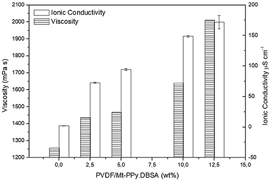
Figure 1. Viscosity (left axis) and ionic conductivity (right axis) of the solution containing different amount of Mt-PPy.DBSA.
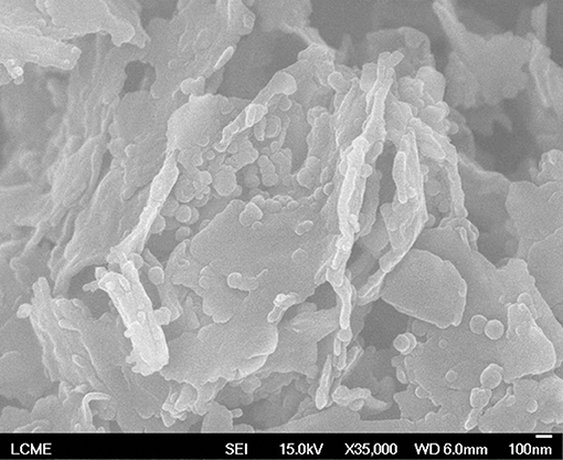
Figure 2. FESEM micrograph of nanostructured conductive additive of Mt-PPy.DBSA.
SEM micrographs of neat PVDF and PVDF/Mt-PPy.DBSA mats containing different amounts of Mt-PPy.DBSA fabricated by electrospinning and solution casting process are shown at Figure 3. Histograms with the diameter distribution of randomly oriented fibers measured by ImageJ free software are also presented. The electrospun PVDF mat (Figure 3A), as already reported by Merlini et al. (2015), has a three-dimensional network structure with randomly oriented fibers, with a mean diameter of 642 ± 153 nm. From the micrographs of mats containing different filler contents (Figures 3B–E), it is possible to notice that the morphology is quite similar, however, for all mats, fibers diameter were modified with addition of the additive. The fibers became thinner (seen by the graphics of diameter size distribution at the column on the left) and, as the concentration of filler increased (to 12.5 wt%). Usually, it has been reported in the literature that the increase of solution viscosity, result in fibers with larger diameters, due to the greater difficulty to eject the polymer solution from the needle (Merlini et al., 2015). However, in this work, the increase of the ionic conductivity also occurred, which may have strongly influenced the results, since the ionic transport is accelerated/reinforced by the electric current, inducing a greater stretching of the fibers during the process. As reported by Merlini et al. (2018) under the electrical field, by increasing the charge density, high elongation forces are imposed on the solution jet, resulting in thinner fibers and also, the production of beads-free fibers. Moreover, agglomerates outside of the fibers (highlighted at the image) can be seen in the mats with 12.5 wt% of filler, due to the higher amount of Mt-PPy.DBSA in the solution, which hampers the dispersion and distribution of the additive particles.
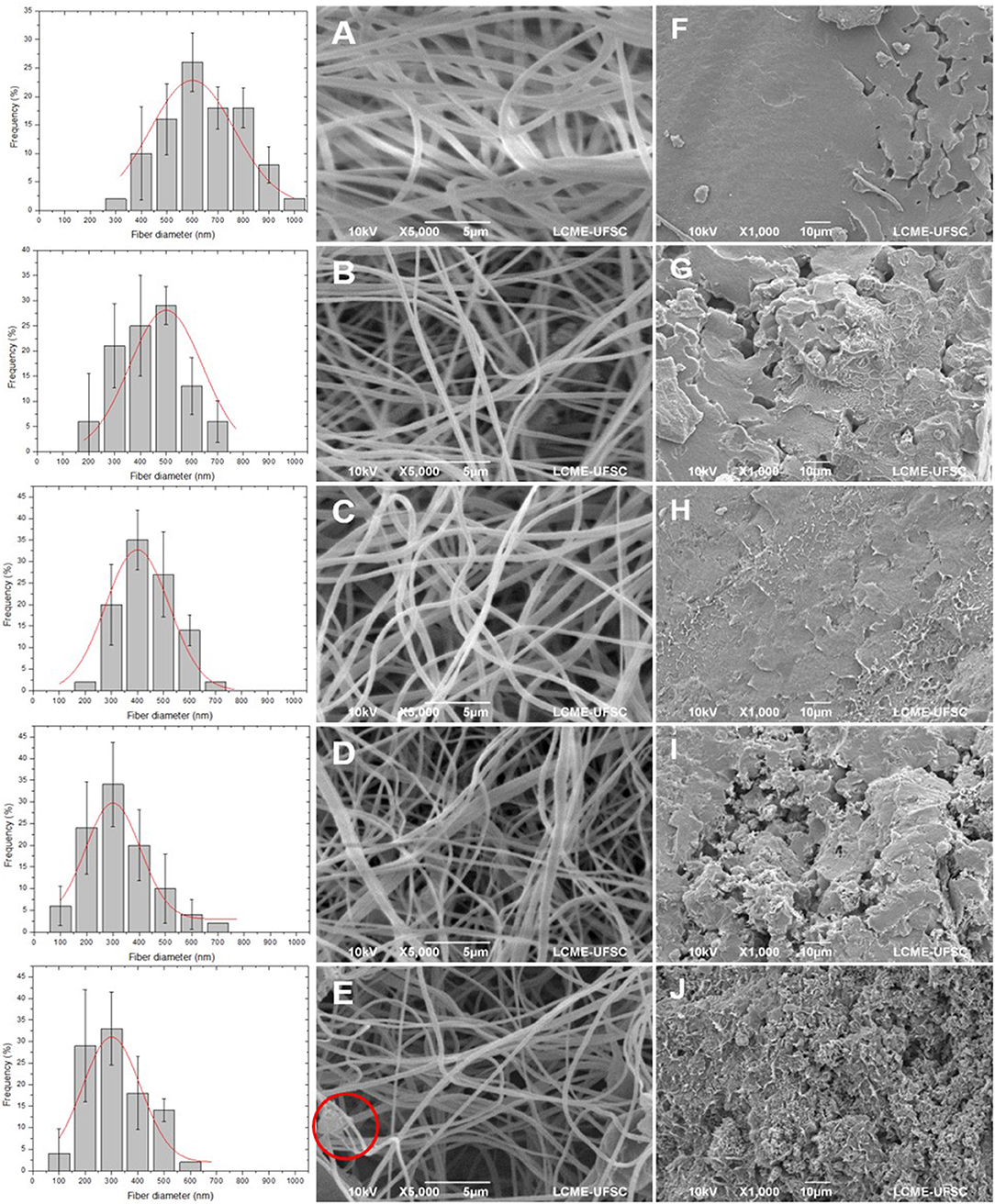
Figure 3. SEM micrographs of the electrospun mats (middle) and membranes fabricated by solution casting (right): (A,F) PVDF, (B,G) PVDF/Mt-PPy.DBSA [2.5], (C,H) PVDF/Mt-PPy.DBSA [5], (D,I) PVDF/Mt-PPy.DBSA [10], (E,J) PVDF/Mt-PPy.DBSA [12.5]. The histograms are also reported.
Figures 3F–J, show the micrographs of all nanocomposites containing 0.0, 2.5, 5.0, 10.0, and 12.5 wt% of Mt-PPy.DBSA developed by solution casting process. A completely different morphology is observed, if compared to electrospinning mats, with a dense structure and low pores density. It is evident that with the increase of additive concentration, the sample microstructure became rougher, generating more and more porosity due to the formation of agglomerates.
The storage modulus curves (E′) loss factor (Tan δ) as a function of the temperature for the electrospun mats and membranes fabricated by solution casting of neat PVDF and PVDF/Mt-PPy.DBSA are shown in Figures 4A–D. It is important to highlight the decrease of E′ (Figures 4A,B) with the increase of temperature, due to the softening of the polymeric chains. Virtually throughout the temperature range for electrospun mats (Figure 4A), E′ values of PVDF are slightly higher than those found to PVDF/Mt-PPy.DBSA mats. This effect can be attributed to the presence of Mt-PPy.DBSA agglomerates, in the electrospun fibers that induce defects in the structure, reducing the storage modulus. However, this variation, caused by the increase of the additive concentration, is very low comparing with the difference between the storage modulus values for the electrospun mats and dense membranes. The last one (Figure 4B) displays storage modulus from 2,000 MPa up to almost 3,000 MPa, which is around 100 times higher than the electrospun mats values. This behavior can be related to a denser microstructure of membranes prepared by solution casting (Figures 3F–J), when compared to those electrospun mats, which have high porosity, and flexibility. Furthermore, membranes fabricated by solution casting display an opposite behavior when compared to the electrospun mats, for which the modulus increases with the increase of the filler amount, over the entire temperature range. This performance can be explained due to the mechanical reinforcement caused by the conductive additive that display partially exfoliated layers. The behavior obtained in this work for PVDF/Mt-PPy.DBSA is consistent with those reported in the literature for TPU/Mt-PPy.DBSA. Merlini et al. (2018) reported very low mechanical properties for TPU/Mt-PPy.DBSA electrospun mats when compared to nanocomposites prepared by melting process, in the study reported by da Silva Ramôa (2015).
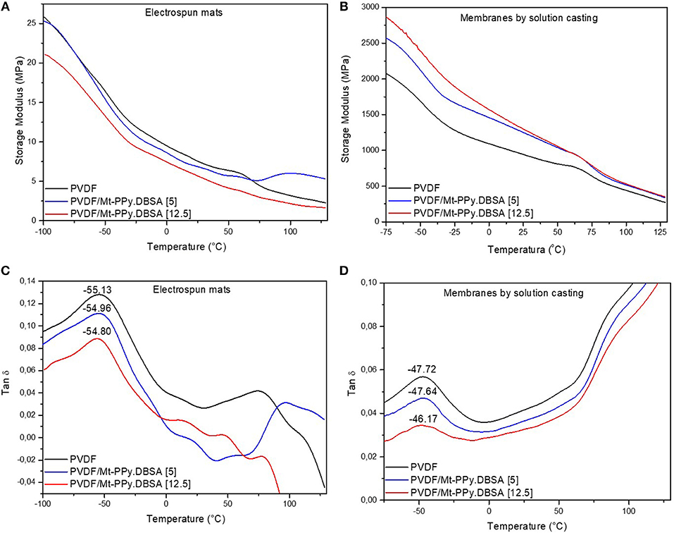
Figure 4. DMTA traces (A,B) storage modulus and loss factor (C,D) of electrospun mats and membranes fabricated by solution casting.
From the loss tangent curves (Tan δ) it is possible to see the peak related to the glass transition temperature (Tg) at around −55°C for electrospun mats (Figure 4C) and −46°C for membranes fabricated by solution casting (Figure 4D). The lower Tg values for electrospun mats indicates that the electrospinning can induce to a higher molecular organization, reducing the secondary bonds strength between polymer molecules. Therefore, lower energy is required to achieve molecular movement of amorphous phase. Moreover, Tg values are not influenced by the amount of the filler in both nanocomposites, but the intensity of the peak related to the glass transition temperature reduces significantly as the concentration of Mt-PPy.DBSA in the membrane increases. A second peak at superior temperatures to 70°C corresponds to the relaxation process associated with molecular motions of crystalline fraction (Merlini, 2014), and are affected by the presence of Mt-PPy.DBSA.
FTIR spectra of Mt-PPy.DBSA, PVDF, and PVDF/Mt-PPy.DBSA are shown at Figures 5A,B. According to previous studies of da Silva Ramôa (2015), Mt presents a broad band at 995 cm−1, which is assigned to the stretching of Si-O-Si groups (da Silva Ramôa, 2015). However, in the spectra of Mt-PPy.DBSA the intensity of the bands associated to the mode of vibration of Si-O-Si groups decreased, indicating the presence of PPy on Mt. The spectrum of Mt-PPy.DBSA exhibits absorption bands at 1,511 and 1,414 cm−1, that correspond to the stretching vibrations of C-C and C-N groups of the pyrrole ring. Absorption band at 1,264 cm−1 is assigned to the deformation in the plane of C-H or C-N bonds, while at 1,110 cm−1 represents deformation in the plane of C-H bonds. Furthermore, deformations at the vibrational plane of N+H2 (formed in doped PPy) entail absorption band at 1,080 cm−1 whereas, bands at 988 and 953 cm−1 are related to the vibrational deformation in and out of the C-H bonds plane of pyrrole ring.
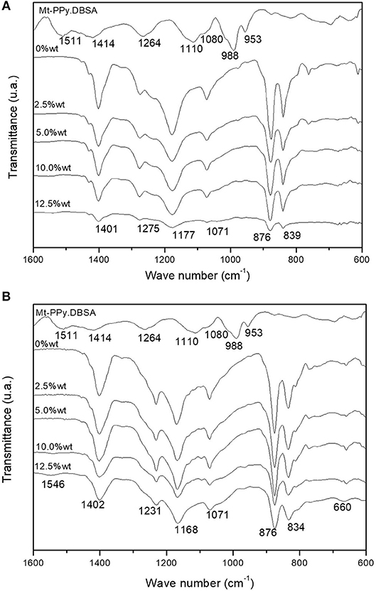
Figure 5. FTIR spectra of PVDF and PVDF/Mt-PPy.DBSA (2.5, 5.0, 10.0, and 12.5 wt%) for (A) electrospun mats and (B) membranes by solution casting.
PVDF has a polymorphic structure, and can present different crystalline structures depending on its processing conditions: as alpha (α), beta (β), gamma (γ), and delta (δ) (Zheng et al., 2007). From the PVDF spectra of electrospun mats and membranes fabricated by solution casting it is possible to note that they display bands assigned to various crystalline phases. Electrospun mats display bands at 1,401 and 876 cm−1 (amorphous phase bands) corresponding to the C-F vibrational stretching and the 1,177 cm−1 band is attributed to the C-C bonds (Kim et al., 2011; Merlini, 2014). In addition to, bands at 1,275, 1,071, and 839 cm−1 are associated to the β phase (Gregorio and Borges, 2008; Merlini, 2014). In membranes produced by solution casting, characteristic bands of amorphous phase were observed at 1,402, 876, and 1,168 cm−1 (and bands associated to the β phase at 1,071 and 834 cm−1, similar to those of the electrospun mats (Gregorio and Borges, 2008; Kim et al., 2011; Merlini et al., 2014). Moreover, bands at 660 and 1,231 cm−1 are related, respectively, to α and γ phase (Yu and Cebe, 2009; Wu et al., 2011). The electrospun fibers mats spectrum showed predominance of β phases (which offers the piezoelectric properties), if compared to the solution casting dense membranes spectrum. This result suggests that electrospinning could induced the formation of the β piezoelectric phase in the PVDF mats. The FTIR spectra of PVDF/Mt-PPy.DBSA shows absorption bands similar to those of neat PVDF, however, membranes produced by casting with 12.5 wt% of filler presents a stronger band at 1,546 cm−1, related to the pyrrole ring vibration.
Figure 6 shows the variation of electrical conductivity (σ) (Scm−1) as a function of Mt-PPy.DBSA concentration for membranes fabricated by solution casting and electrospun mats. It can be observed that the electrical conductivity of dense membranes increases sharply from 3.93 × 10⁻¹⁵ to 0.36 S cm−1 with Mt-PPy.DBSA contents from 0 to 12.5 wt%, respectively. However, the electrical conductivity obtained for electrospun mats did not show a significant growth with the increment of Mt-PPy.DBSA concentration, ranging from 7.06 × 10⁻¹⁸ S cm−1 (raw PVDF) up to 6.13 × 10⁻¹⁴ S cm−1 for the PVDF with 12.5 wt% of additive. This behavior can be explained by the morphology, that displays a fibrous and highly porous structure (shown at Figure 3) as well as the fact that the nanostructured conductive additive is encapsulated within the fibers, preventing conductive paths formation.
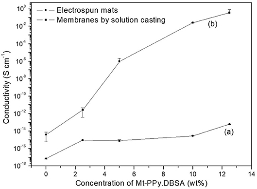
Figure 6. Electrical conductivity of (A) electrospun mats and (B) membranes fabricated by solution casting.
Table 1 shows electrical conductivity of electrospun mats with different composition. The electrical conductivity values obtained in this work are significantly lower than those reported in the literature, however, usually significantly high amount of conducting polymer are used to achieve these elevated values. As can be seen in Table 1, electrospun mats can display different ranges of conductivities depending on several factors, as for example, types of polymers, additives, and other chemicals (solvents, dopants, oxidizing agents, etc.), ratios between the components, compactness, and homogeneity of the mats. According to the review work reported by Yanilmaz and Sarac (2014), after investigating several studies, it was reported that the high porosity of fibrous mat structure limits the contact of conductive segments, and high level of conductivity required for many applications may not be achieved.
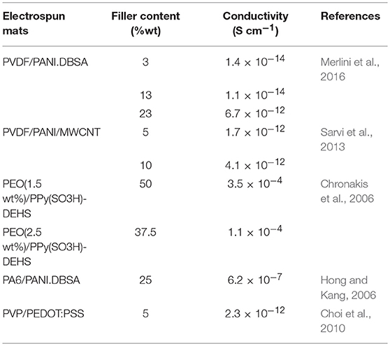
Table 1. Electrical conductivity for different conductive electrospun mats.
The EMI SE can be defined as the attenuation of electromagnetic waves performed by the shielding material (Merlini et al., 2017). The total EMI SE is described as a sum of three EMI attenuation mechanisms: reflection loss (SER); absorption (SEA) and multiple internal reflection loss at the material interface (SEM). According to Ramoa et al. (2018) SEM cannot be measured as separated factor; therefore, they were disregard in this study (Im et al., 2010; Al-Saleh et al., 2011).
In order to investigate the contribution of reflection and absorption to the total EMI SE of the composites, Transmittance (T) and Reflectance (R) powers were calculated through the scattering parameters. That represent the reflection S11 (S22) and transmission S12(S21) coefficients, from the vector network analyzer, as described by Equations (3) and (4) (Al-Saleh et al., 2011; Ramoa et al., 2013, 2018;Vargas et al., 2018).
The absorbed coefficient (A), as product of incident (I), transmitted (T) and reflected (R) waves, was calculated according to Equation (5), considering 1 (Merlini et al., 2017).
Herewith, the total EMI average, absorption loss (SEA) and reflection loss (SER) were calculated on the basis of transmittance (T) and reflectance (R) coefficients, according to Equations (6–8) (Al-Saleh et al., 2011; Ramoa et al., 2013, 2018; Vargas et al., 2018).
Figure 7 shows the EMI SE of investigated electrospun mats and dense membranes as a function of weight fraction of Mt-PPy.DBSA filler, over the frequency range of 8.2–12.4 GHz. It is possible to note that EMI SE of electrospun mats is practically null (lower than −2dB), indicating that they are almost transparent to magnetic waves, even with higher concentration of additive (12.5 wt%). This behavior was not expected since works in the literature have demonstrated the potential use of electrospun mats for electromagnetic shielding applications, especially due to the high surface area to interact with the radiation (Im et al., 2010). However, Im et al. (2010) reported a great EMI SE of −42 dB to MWCNT embedded PANI/PEO-based fibers, when a very high amount of fluorinated MWCNTs (120 wt%) were embedded in the PANI/PEO fibers. The low EMI SE of PVDF/Mt-PPy.DBSA electrospun mats can be explained by the low values of electrical conductivity of the mats, as reported previously, as well as the low amount of Mt-PPy.DBSA incorporated into the fibers. The electrical conductivity has been shown to be a critical factor in the development of electromagnetic radiation attenuating materials and required conductivity levels are >102 S m−1 for electromagnetic shielding applications (Sudha et al., 2009). Moreover, these mats display lower thickness (0.15 mm) when compared to conventional nanocomposites used for EMI SE (2 mm). According to the literature (Vargas et al., 2018), EMI SE is significantly influenced by the nanocomposites thickness. Vargas et al. (2018) reported that, by increasing thickness of PU/Mt-PPy.DBSA nanocomposites from 2 to 8 mm, the EMI SE increases from −20.8 to −60.3 dB, when 25 wt% of Mt-PPy.DBSA.
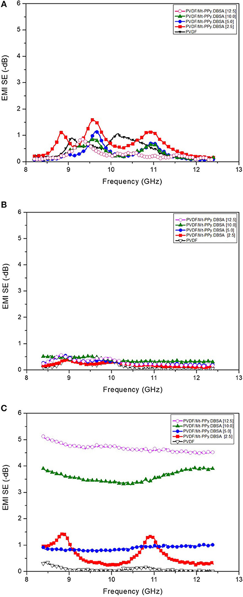
Figure 7. EMI SE in the X-band frequency range for (A) electrospun mats of PVDF/Mt-PPy.DBSA and (B,C) membranes of PVDF/Mt-PPy.DBSA fabricated by solution casting process with thickness of 0.15 mm and 0.25 mm, respectively.
It is possible to note that the EMI SE of membranes produced by solution casting (Figure 7B) is quite similar to those values reported for electrospun mats, even that the electrical conductivity of these membranes are superior to those of electrospun mats. This behavior can be associated to the low thickness (0.15 mm), which allows the transmission of the wave through the material. In order to analyze the effect of the thickness, thicker membranes (0.25 mm) were produced by solution casting. For these membranes (Figure 7C) the EMI SE increased with the Mt-PPy.DBSA loading, indicating that a better interaction of the conductive filler with the radiation. For membranes with lower filler content, the EMI SE values varied over the frequency range, but became almost independent of frequency with the increase of Mt-PPy.DBSA amount. This behavior can be explained due to the reduction of the material skin depth with increasing filler content into the nanocomposites (Al-Hartomy et al., 2011; Choudhary and Gupt, 2011; Ramoa et al., 2018). It is important to highlight that was not possible to fabricate electrospun mats with thickness higher than 0.15 mm.
The contribution of reflection and absorption in the total EMI SE for thicker membranes produced by solution casting is reported at Figure 8. The results are expressed as average values in the frequency range of 8.2–12.4 GHz. It is possible to note that the shielding by reflection and absorption contribute to the total electromagnetic shielding and the contribution of both mechanism increases with the filler loading, resulting in higher EMI SE. The SEA becomes the main EMI shielding mechanism, similar to the results reported by Vargas et al. (2018) for nanocomposites containing Mt-PPy.DBSA.
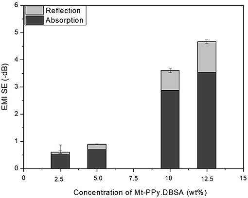
Figure 8. Effect of conductive filler content on the total EMI SE average, absorption loss (SEA) and reflection loss (SER) of PVDF/Mt-PPy.DBSA membranes by solution casting with a thickness average of 0.25 mm.
Non-woven mats of PVDF containing different weight fractions of Mt-PPy.DBSA were successfully obtained by electrospinning. The fibers diameter of electrospun mats decreased with the increase of additive loading, due to a higher elongation imposed to the solution caused by the higher ionic conductivity. Mats produced by electrospinning display the piezoelectric phase, indicating effectiveness of this process to produce β phase. Electrospun mats behave as insulating material with electrical conductivity ranging from 10−18 to 10−14 S cm−1 due to the highly porous structure and encapsulation of the filler. Moreover, they did not achieve a satisfactory EMI SE due to the low electrical conductivity and thickness. However, membranes produced by solution casting, showed superior mechanical properties, electrical conductivity (10−2 S cm−1) and those with higher thickness achieve to EMI SE of −5 dB with 12.5 wt% Mt-PPy.DBSA. The values obtained for both systems remains below to that required for commercial application (−20 dB), indicating that is necessary to expand the studies related to shielding efficiency, in order to conclude if these materials are feasible for this application.
All datasets generated for this study are included in the manuscript and/or the supplementary files.
SR performed the synthesis of the additives. VS fabricated the electrospun mats and dense membranes, performed the characterizations and wrote the article. CM assisted in writing of the manuscript and discussion of results. GB conducted the discussion of results. All authors reviewed the final manuscript.
The authors declare that the research was conducted in the absence of any commercial or financial relationships that could be construed as a potential conflict of interest.
The authors acknowledge the financial support of Conselho Nacional de Desenvolvimento Científico e Tecnológico (Process: 406286/2018-3), Coordenação de Aperfeiçoamento de Pessoal de Ensino Superior (CAPES), and Fundação de Amparo à Pesquisa e Inovação do Estado de Santa Catarina (FAPESC). In addition, we extend our sincere gratitude to the Central Electronic Microscopy Laboratory, Federal University of Santa Catarina (LCME-UFSC).
Agarwal, S., Greimer, A., and Wendorff, J. H. (2009). Electrospinning of manmade and biopolymer nanofibers - progress in techniques, materials, and applications. Adv. Funct. Mater. 19, 2863–2879. doi: 10.1002/adfm.200900591
Agarwal, S., Greiner, A., and Wendorff, J. H. (2013). Functional materials by electrospinning of polymers. Prog. Polym. Sci. 38, 963–991. doi: 10.1016/j.progpolymsci.2013.02.001
Al-Hartomy, O. A., Al-Salamy, F., Al-Ghamdi, A. A., Abdel Fatah, M., Dishovsky, N., and El-Tantawy, F. (2011). Influence of graphite nanosheets on the structure and properties of PVC-based nanocomposites. J. Appl. Polym. Sci. 120, 3628–3634. doi: 10.1002/app.33547
Al-Saleh, M. H., Gelves, G. A., and Sundararaj, U. (2011). Copper nanowire/polystyrene nanocomposites: lower percolation threshold and higher EMI shielding. Compos. Part A Appl. Sci. Manuf. 42, 92–97. doi: 10.1016/j.compositesa.2010.10.003
Choi, J., Lee, J., Choi, J., Jung, D., and Shim, S. E. (2010). Electrospun PEDOT:PSS/PVP nanofibers as the chemiresistor in chemical vapour sensing. Synth. Met. 160, 1415–1421. doi: 10.1016/j.synthmet.2010.04.021
Choudhary, V., and Gupt, A. (2011). “Polymer/carbon nanotube nanocomposites,” in Carbon Nanotubes - Polymer Nanocomposites, ed S. Yellampalli (Delhi: InTech), 65–90.
Chronakis, I. S., Grapenson, S., and Jakob, A. (2006). Conductive polypyrrole nanofibers via electrospinning: electrical and morphological properties. Polymer 47, 1597–1603. doi: 10.1016/j.polymer.2006.01.032
Das, N. C., Liu, Y., Yang, K., Peng, W., Maiti, S., and Wang, H. (2009). Single-walled carbon nanotube/poly(methyl methacrylate) composites for electromagnetic interference shielding. Polym. Eng. Sci. 49, 1627–1634. doi: 10.1002/pen.21384
da Silva Ramôa, S. D. A., Barra, G. M. O., Merlini, C., Schreiner, W. H., Livi, S., Soares, B. G., et al. (2015). Production of montmorillonite/polypyrrole nanocomposites through in situ oxidative polymerization of pyrrole: effect of anionic and cationic surfactants on structure and properties. Appl. Clay Sci. 104, 160–167. doi: 10.1016/j.clay.2014.11.026
da Silva Ramôa, S. D. A. (2015). Síntese, caracterização e avaliação da utilização de aditivo condutor nanoestruturado à base de montmorilonita/polipirrol em matriz de poliuretano termoplástico para aplicação em blindagem eletromagnética. (Doctoral's thesis). Federal University of Santa Catarina, Florianópolis, Brazil.
Gregorio, R., and Borges, D. S. (2008). Effect of crystallization rate on the formation of the polymorphs of solution cast poly(vinylidene fluoride). Polymer 49, 4009–4016. doi: 10.1016/j.polymer.2008.07.010
Greiner, A., and Wendorff, J. H. (2007). Electrospinning: a fascinating method for the preparation of ultrathin fibers. Angew. Chem. Int. Ed. 46, 5670–5703. doi: 10.1002/anie.200604646
Hong, K. H., and Kang, T. J. (2006). Polyaniline-nylon 6 composite nanowires prepared by emulsion polymerization and electrospinning process. J. Appl. Polym. Sci. 99, 1277–1286. doi: 10.1002/app.22654
Idris, F. M., Hashim, M., Ibrahim, I. R., Ismail, I., Abbas, Z., Nazlan, R., et al. (2015). Recent developments of smart electromagnetic absorbers based polymer-composites at gigahertz frequencies. J. Magn. Magn. Mater. 405, 197–208. doi: 10.1016/j.jmmm.2015.12.070
Im, J. S., Kim, J. G., Lee, S.-H., and Lee, Y.-S. (2010). Enhanced adhesion and dispersion of carbon nanotube in PANI/PEO electrospun fibers for shielding effectiveness of electromagnetic interference. Colloids Surfaces A Physicochem. Eng. Asp. 364, 151–157. doi: 10.1016/j.colsurfa.2010.05.015
Im, J. S., Kim, J. G., and Lee, Y.-S. (2009). Fluorination effects of carbon black additives for electrical properties and EMI shielding efficiency by improved dispersion and adhesion. Carbon 47, 2640–2647. doi: 10.1016/j.carbon.2009.05.017
Ji, H., Zhao, R., Zhang, N., Jin, C., Lu, X., and Wang, C. (2018). Lightweight and flexible electrospun polymer nanofiber/metal nanoparticle hybrid membrane for high-performance electromagnetic interference shielding. NPG Asia Mater. 10, 749–760. doi: 10.1038/s41427-018-0070-1
Jin, J., Song, J., Deng, S., and Li, G. (2016). Synthesis and microwave absorbing characteristics of flake-like polypyrrole filled composites in X-band. Polym. Compos. 37, 1137–1142. doi: 10.1002/pc.23209
Jin, X., Ni, Q.-Q., Fu, Y., Zhang, L., and Natsuki, T. (2012). Electrospun nanocomposite polyacrylonitrile fibers containing carbon nanotubes and cobalt ferrite. Polym. Compos. 33, 317–323. doi: 10.1002/pc.21251
Kim, H. K., Kim, M. S., Song, K., Park, Y. H., Kim, S. H., Joo, J., et al. (2003). EMI shielding intrinsically conducting polymer/PET textile composites. Synth. Met. 135–136, 105–106. doi: 10.1016/S0379-6779(02)00876-7
Kim, Y. J., Ahn, C. H., Lee, M. B., and Choi, M. S. (2011). Characteristics of electrospun PVDF/SiO2 composite nanofiber membranes as polymer electrolyte. Mater. Chem. Phys. 127, 137–142. doi: 10.1016/j.matchemphys.2011.01.046
Lakshmi, K., John, H., Mathew, K. T., Joseph, R., and George, K. E. (2009). Microwave absorption, reflection and EMI shielding of PU-PANI composite. Acta Mater. 57, 371–375. doi: 10.1016/j.actamat.2008.09.018
Li, D., and Xia, Y. (2004). Electrospinning of nanofibers: reinventing the wheel? Adv. Mater. 16, 1151–1170. doi: 10.1002/adma.200400719
Liao, Y., Loh, C. H., Tian, M., Wang, R., and Fane, A. G. (2018). Progress in electrospun polymeric nanofibrous membranes for water treatment: fabrication, modification and applications. Prog. Polym. Sci. 77, 69–94. doi: 10.1016/j.progpolymsci.2017.10.003
Liu, P., Huang, Y., and Zhang, X. (2015). Synthesis, characterization and excellent electromagnetic wave absorption properties of graphene@CoFe2O4@polyaniline nanocomposites. Synth. Met. 201, 76–81. doi: 10.1016/j.synthmet.2015.01.022
Long, Y. Z., Li, M. M., Gu, C., Wan, M., Duvail, J. L., Liu, Z., et al. (2011). Recent advances in synthesis, physical properties and applications of conducting polymer nanotubes and nanofibers. Prog. Polym. Sci. 36, 1415–1442. doi: 10.1016/j.progpolymsci.2011.04.001
Luzio, A., Canesi, E. V., Bertarelli, C., and Caironi, M. (2014). Electrospun polymer fibers for electronic applications. Materials 7, 906–947. doi: 10.3390/ma7020906
Merlini, C. (2014). Desenvolvimento de membranas eletrofiadas de poli (fluoreto de vinilideno) com polipirrol para aplicação em sensores de compressão (Doctoral's thesis). Federal University of Santa Catarina, Florianópolis, Brazil.
Merlini, C., Barra, G. M. O., Medeiros Araujo, T., and Pegoretti, A. (2014). Electrically pressure sensitive poly(vinylidene fluoride)/polypyrrole electrospun mats. RSC Adv. 4, 15749–15758. doi: 10.1039/C4RA01058B
Merlini, C., Contri, G., de Oliveira Barra, G. M., da Silva Ramôa, S. D. A., Soares, B. G., D'Ávila, M., et al. (2015). Electrically conductive polyaniline-coated electrospun poly(vinylidene fluoride) mats. Front. Mater. 2:14. doi: 10.3389/fmats.2015.00014
Merlini, C., Pegoretti, A., Araujo, T. M., Ramoa, S. D. A. S., Schreiner, W. H., and De Oliveira Barra, G. M. (2016). Electrospinning of doped and undoped-polyaniline/poly(vinylidene fluoride) blends. Synth. Met. 213, 34–41. doi: 10.1016/j.synthmet.2015.12.024
Merlini, C., Pegoretti, A., Vargas, P. C., Cunha, T. F., da Ramôa, S. D. A. S., Soares, B. G., et al. (2017). Electromagnetic interference shielding effectiveness of composites based on polyurethane derived from castor oil and nanostructured carbon fillers. Polym. Compos. 37, 1137–1142. doi: 10.1002/pc.24501
Merlini, C., Silveira, A., Ramôa, S. D. A. S., Soares, B. G., Alavarse, A. C., Bonvent, J. J., et al. (2018). A comparative study of aligned and random electrospun mats of thermoplastic polyurethane and conductive additives based on polypyrrole. Polym. Test. 70, 486–497. doi: 10.1016/j.polymertesting.2018.08.002
Moučka, R., Mravčáková, M., Vilčáková, J., Omastová, M., and Sáha, P. (2011). Electromagnetic absorption efficiency of polypropylene/montmorillonite/polypyrrole nanocomposites. Mater. Des. 32, 2006–2011. doi: 10.1016/j.matdes.2010.11.064
Ni, Q.-Q., Xia, H., Jin, X., and Liu, F. (2015). “Application of electrospun nanofibers in electromagnetic interference shielding,” in Electrospun Nanofibers for Energy and Environmental Applications, eds J. David, B. Lockwood, Ding, and J. Yu (Ueda: Springer), 518.
Nthumbi, R. M., Adelodun, A. A., and Ngila, J. C. (2017). Electrospun and functionalized PVDF/PAN composite for the removal of trace metals in contaminated water. Phys. Chem. Earth 100, 225–235. doi: 10.1016/j.pce.2016.08.007
Obaid, M., Mohamed, H. O., Yasin, A. S., Fadali, O. A., Khalil, K. A., Kim, T., et al. (2016). A novel strategy for enhancing the electrospun PVDF support layer of thin-film composite forward osmosis membranes. RSC Adv. 6, 102762–102772. doi: 10.1039/C6RA18153H
Pirvu, C., Manole, C. C., Stoian, A. B., and Demetrescu, I. (2011). Understanding of electrochemical and structural changes of polypyrrole/polyethylene glycol composite films in aqueous solution. Electrochim. Acta 56, 9893–9903. doi: 10.1016/j.electacta.2011.08.061
Qiao, J., Liu, J., Liu, W., Wang, F., Zhang, X., Xu, D., et al. (2018). Self-assembled ZnO/Co hybrid nanotubes prepared by electrospinning for lightweight and high-performance electromagnetic wave absorption. ACS Appl. Nano Mater. 1, 5297–5306. doi: 10.1021/acsanm.8b01303
Qin, F., and Brosseau, C. (2012). A review and analysis of microwave absorption in polymer composites filled with carbonaceous particles. J. Appl. Phys. 111:061301. doi: 10.1063/1.3688435
Ram, R., Rahaman, M., and Khastgir, D. (2019). “Electromagnetic interference (EMI) shielding effectiveness (SE) of polymer-carbon composites,” in Carbon-Containing Polymer Composites, eds M. Rahaman, D. Khastgir, and A. Aldalbahi (Singapore: Springer), 339–368. doi: 10.1007/978-981-13-2688-2_10
Ramoa, S. D. A. S., Merlini, C., Soares, B. G., Barra, G. M. O., Pegoretti, A., and Livi, S. (2018). Electromagnetic interference shielding effectiveness and microwave absorption properties of thermoplastic polyurethane/montmorillonite-polypyrrole nanocomposites. Polym. Adv. Technol. 29, 1377–1384. doi: 10.1002/pat.4249
Ramoa, S. D. A. S., Soares, B. G., Oliveira, R. V., de Oliveira, M. G., Cossa, M., and Barra, G. M. O. (2013). Electrical, rheological and electromagnetic interference shielding properties of thermoplastic polyurethane/carbon nanotube composites. Polym. Int. 62, 1477–1484. doi: 10.1002/pi.4446
Reneker, D. H., and Fong, H. (2006). “Polymeric nanofibers: introduction,” in Polymeric Nanofibers (Washington, DC: American Chemical Society), 1–6. doi: 10.1021/bk-2006-0918.ch001
Sarvi, A., Chimello, V., Silva, A. B., Bretas, R. E. S., and Sundararaj, U. (2013). Coaxial electrospun nanofibers of poly(vinylidene fluoride)/polyaniline filled with multi-walled carbon nanotubes. Polym. Compos. 35, 1198–1203. doi: 10.1002/pc.22768
Sudha, J. D., Radhakrishnan Nair, P., Reena, V. L., Prasanth, R., and Sivakala, S. (2009). Development of electromagnetic shielding materials from the conductive blends of polyaniline and polyaniline-clay nanocomposite-EVA: preparation and properties. Compos. Sci. Technol. 69, 358–364. doi: 10.1016/j.compscitech.2008.10.026
Vargas, P. C., Merlinia, C., Ramôaa, S. D. A., da, S., Arenharta, R., Barra, G. M. de, O., et al. (2018). Conductive composites based on polyurethane and nanostructured conductive filler of montmorillonite/polypyrrole for electromagnetic shielding applications. Mater. Res. 21:e20180014. doi: 10.1590/1980-5373-mr-2018-0014
Wu, N., Cao, Q., Wang, X., and Chen, Q. (2011). Study of a novel porous gel polymer electrolyte based on TPU/PVdF by electrospinning technique. Solid State Ionics 203, 42–46. doi: 10.1016/j.ssi.2011.08.020
Yan, D.-X., Ren, P.-G., Pang, H., Li, Z.-M., Fu, Q., and Yang, M.-B. (2012). Efficient electromagnetic interference shielding of lightweight graphene/polystyrene composite. J. Mater. Chem. 22:18772. doi: 10.1039/c2jm32692b
Yanilmaz, M., and Sarac, A. S. (2014). A review: effect of conductive polymers on the conductivities of electrospun mats. Text. Res. J. 84, 1325–1342. doi: 10.1177/0040517513495943
Yu, L., and Cebe, P. (2009). Crystal polymorphism in electrospun composite nanofibers of poly(vinylidene fluoride) with nanoclay. Polymer 50, 2133–2141. doi: 10.1016/j.polymer.2009.03.003
Keywords: conductive nanocomposites, intrinsically conductive polymers, polypyrrole, montmorillonite, electrospun mats, shielding effectiveness
Citation: Schiefferdecker VM, Barra GMO, Ramôa SDAS and Merlini C (2019) Comparative Study of the Structure and Properties of Poly(Vinylidene Fluoride)/Montmorillonite-Polypyrrole Nanocomposites Prepared by Electrospinning and Solution Casting. Front. Mater. 6:193. doi: 10.3389/fmats.2019.00193
Received: 19 March 2019; Accepted: 25 July 2019;
Published: 13 August 2019.
Edited by:
Yu Dong, Curtin University, AustraliaReviewed by:
Xiaowen Qi, Yanshan University, ChinaCopyright © 2019 Schiefferdecker, Barra, Ramôa and Merlini. This is an open-access article distributed under the terms of the Creative Commons Attribution License (CC BY). The use, distribution or reproduction in other forums is permitted, provided the original author(s) and the copyright owner(s) are credited and that the original publication in this journal is cited, in accordance with accepted academic practice. No use, distribution or reproduction is permitted which does not comply with these terms.
*Correspondence: Claudia Merlini, Y2xhdWRpYS5tZXJsaW5pQHVmc2MuYnI=
Disclaimer: All claims expressed in this article are solely those of the authors and do not necessarily represent those of their affiliated organizations, or those of the publisher, the editors and the reviewers. Any product that may be evaluated in this article or claim that may be made by its manufacturer is not guaranteed or endorsed by the publisher.
Research integrity at Frontiers
Learn more about the work of our research integrity team to safeguard the quality of each article we publish.