 Tao Wang
 Fengli Yang1
 Yao Cui
- 1Key Laboratory of Earthquake Engineering and Engineering Vibration, Institute of Engineering Mechanics, China Earthquake Administration (CEA), Harbin, China
- 2State Key Laboratory of Coastal and Offshore Engineering, School of Civil Engineering, Faculty of Infrastructure Engineering, Dalian University of Technology, Dalian, China
RC coupling beams have been reported to have had serious damages during the 2008 Wenchuan earthquake. Beams are very difficult to repair once cracks occur. To improve the ductility and reparability of the traditional RC coupling beam, a damage-controllable hybrid coupling beam is proposed in this study. The hybrid coupling beam couples the wall limbs by a friction damper connected through steel beam segments. The strength and stiffness of the friction damper are carefully designed to concentrate more deformation on the damper. The friction mechanism could dissipate more energy than the traditional RC coupling beam. The uncertainties introduced by the design process and the inherent characteristics of traditional RC coupling beams or other types of dampers are significantly reduced. High-strength bolts are used for all connections so that it could be quickly replaced once any damage is observed after an earthquake. In this study, a friction damper using semi-metallic friction plates and stainless-steel shims as the contact pair was tested at different loading rates. The temperature was measured. A thermal–mechanical model was then developed to correlate the dissipated energy with the friction coefficient or friction force, which can be easily incorporated into the structural design process. Finally, the hybrid coupling beam was designed and tested quasi-statically. The force, deformation, and energy dissipation capacity were compared with the traditional RC coupling beam, which also demonstrated damage controllability by using the proposed hybrid coupling beam.
Introduction
High-rise buildings often adopt the reinforced concrete (RC) shear wall system as the lateral force resistance member. The dual seismic defense mechanism, i.e., the coupling beams and the shear walls, is particularly suitable to balance comfort living and earthquake safety. During an earthquake, the coupling beams are damaged first, and the entire structure becomes more flexible, thus preventing high-frequency dominated energy entering the structure. Therefore, the coupling beam is often expected to be ductile, as suggested by many seismic design codes (International Code Council (ICC), 2015; MOHURD, 2016a,b). However, more ductility of RC members implies more damage, because the ductility relies on the crack of concrete and yielding of steel rebars. Once the RC coupling beam cracks, it is very difficult to repair, as reported in the 2008 Wenchuan earthquake (Wang, 2008).
The coupling beam, once combined with dampers, also called hybrid coupling beams, is appealing because of its damage controllability that is superior to traditional RC coupling beams. Recent studies (Fortney et al., 2007; Xu, 2007; Teng et al., 2010; Lu et al., 2013; Xu et al., 2016) have demonstrated that the ductility is greatly improved by use of dampers in the coupling beam. A viscoelastic coupling damper was employed by Montgomery and Christopoulos (2015) to enhance the seismic performance of high-rise buildings. The performance of two wall limbs coupled by the viscoelastic link under the wind and the earthquake loads was also validated experimentally. A self-centering damper using SMA wires for the RC coupling beam has been developed to render the system a re-centering capability, which has been demonstrated effective by experiments (Mao et al., 2012). More recently, Ji et al. (2017) proposed a short steel shear link to replace the entire RC coupling beam. Both energy dissipation capacity and quick replaceability have been verified through quasi-static cyclic tests. A 1/2 scaled four-story specimen was constructed, which was installed with low-yield steel coupling beams (Cheng et al., 2015). The connection between the steel coupling beam and the RC shear wall worked well during the entire test. However, most of the configurations mentioned above lack replacement mechansim. The dampers are found difficult to be replaced once damaged. Moreover, some metallic dampers, although connected through bolts, performed significant over-strength, making the connection damaged at large deformations.
To solve these problems, the friction damper is often employed. Theoretically, the friction damper has infinite initial stiffness, and a stable post-sliding force, which is superior to other types of dampers in the coupling beam application, as demonstrated by Ahn et al. (2013) and Ye et al. (2018). Most friction dampers are featured with a line type working in axial direction, such as the Pall friction damper (Pall and Marsh, 1982) and the Sumitomo damper (Aiken et al., 1993). They are often combined with other mechanisms to realize more sophisticated behavior, such as the self-centering damper (Filiatrault et al., 2000) and the semi-actively controlled damper (Xu and Ng, 2008). The energy can also be dissipated by the friction torqued (Mualla and Belev, 2002) or by the bolted connections (Loo et al., 2014). The key to realizing a stable friction behavior is the materials of contact pair. Several types of friction materials have been examined extensively in the past two decades, including the semi-metallic friction material, metallic alloy material, iron-based ceramic material, carbon-based composite material, and so on (Jang et al., 2004; Gurunath and Bijwe, 2007; Yun et al., 2010; Latour et al., 2014; Lee et al., 2016). These studies examined the microscopic behavior of contact surface, such as adhesion, abrasion, fatigue, corrosion, and so on, by using scanning electron microscopy. In engineering practice, it could be difficult to measure such behavior during an earthquake. Instead, displacement, velocity, and force could be obtained from the available design process. Therefore, relating friction behavior to displacement, velocity, or the dissipated energy could be very helpful for the design application.
To this end, this study proposes a friction damper using semi-metallic friction plates and stainless-steel shims as the contact pair. The dampers were tested at different loading rates, and the temperature was measured. A thermal–mechanical model was then developed to correlate the dissipated energy with the friction coefficient or friction force, which can be easily incorporated into the structural design process. Finally, the hybrid coupling beam was designed and tested quasi-statically. The force, deformation, and energy dissipation capacity were compared with the traditional RC coupling beam, and conclusions are given to provide design guidance.
Mechanical Behavior of Friction Damper
Friction dampers are featured with an infinite initial stiffness and almost constant slip force, which are very appealing because the larger stiffness is helpful to resist the wind load and small or moderate earthquakes, while the constant slip force prevents unpredictable force transferred into the primary structural member due to the over-strength effect. This study developed a friction damper that works in the shear direction to adapt to the deformation of coupling beams. Although it works in the shear deformation mode, the configuration is similar to those working the axial direction.
Configuration of the Friction Damper
The proposed shear-type friction damper is configured as in Figure 1. It is primarily composed of five parts, i.e., one T-shaped inner steel plate pasted with one piece of 2-mm-thick stainless-steel shim on each surface, two pieces of friction plates made of semi-steel friction material commonly used as the brakes, and two pieces of L-shaped outer steel plates having two restrainers at both sides to confine the friction plates from movement. The friction material contains steel fibers, resin-based material, adhesives, rubber, and asbestos. Preliminary tests on the material showed a stable friction coefficient, high-pressure resistance, small abrasion, and low friction noise. Bolt holes are placed on the flanges of the inner and outer plates through which the damper can be connected to the main structures. Two friction pairs are formed between the friction plates and the stainless-steel shims. It should be noted that although the outer plate is also contacted with the friction plate, there is no relative movement on the interface because of the restrainers. Two high-strength bolts of Grade 10.9 penetrating all plates are used to provide the contact pressure. The diameter of the high-strength bolts is 20 mm. In order to reduce the stress relaxation, six pieces of disc springs are used as the washers for each high-strength bolt, three pieces for each side. The three pieces of disc springs work in a parallel mode. There is a slot for the bolts on the web of the inner plates and the associated stainless-steel shims, because of which, the inner plate can move smoothly in the shear direction. The dampers are usually installed after the construction of the primary structure. When installing the damper, the components are first assembled by the high-strength bolts with 10–30% of the expected load. At this moment, the height of the damper shall be smaller than the installation space. After positioning the damper, the bolts on the flanges of the inner and outer plates are securely tightened. A slight sliding in the vertical direction is allowed. Therefore, the holes in the friction plates and the slot in the inner plate shall be large enough to accommodate such slippage. Once the bolts on the flanges of the inner and outer plates are tightened, the two high-strength bolts are screwed by the torque wrench to the designed value. Two ways could be employed to achieve the design contact pressure. One is to calibrate the relationship of the pressure with respect to the torque of high-strength bolts (Cavallaro et al., 2018). The other is to relate the deformation of disc springs to the pressure, and the stiffness of the disc spring shall be verified experimentally.
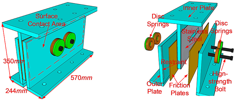
Figure 1. Configuration of proposed friction damper.
Loading Setup and Measurement Scheme
In order to demonstrate the mechanical behavior of the proposed friction damper and develop an equation to predict the behavior for the design, cyclic tests were conducted. The test setup is given in Figure 2, where the friction damper is installed within a pin-connected loading frame. The flanges of the damper are connected to the upper and lower connectors, respectively, which are further connected to the upper and lower jigs. The upper jig is securely fixed on the bottom flange of the loading beam. To the left end of the loading beam is attached a dynamic actuator. The maximum force of the actuator is 50 tons, the stroke is 0.5 m, and the largest loading rate is 0.6 m/s. The lower jig is attached to an adapter with free adjustability in the vertical direction. With this mechanism of adapter, the high-strength bolts can be completely screwed to the design value before the installation. The adapter is fixed on the top of the foundation beam, which is securely fixed on the strong floor by eight anchor rebars with a diameter of 70 mm. The loading beam and the foundation beam are connected by two columns through four hinges. The inherent friction force provided by the loading frame can be ignored. The distance between the hinges at both ends of a column is 2.07 m. Considering the limited design stroke of the damper, 40 mm in this study, the vertical deformation introduced by the second-order effect is 0.4 mm, whose influence on the lateral behavior of the damper can be ignored.
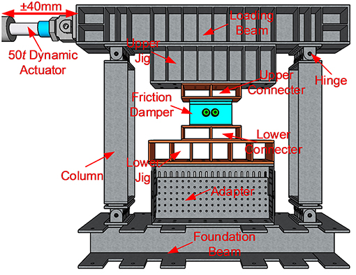
Figure 2. Loading setup for the friction damper.
The loading profile adopts 100 cycles of a sine wave with an amplitude of 40 mm in the actuator. The real deformation applied on the damper might be smaller due to the deformation of the loading frame and slippage on connecting surfaces. Different loading frequencies, denoted as f , are adopted, i.e., 0.02, 0.1, 0.5, and 1.0 Hz. The design tensile force of M20 Grade 10.9 high-strength bolt is 155 kN. Three levels of tightening force, denoted as P, are designed for each high-strength bolt, i.e., 80, 120, and 140 kN. Three specimens were tested, each with different tightening forces. The loading sequence can be found in Table 1, where the averaged tightening force directly measured at the beginning of each test is also given.
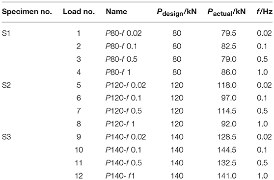
Table 1. Loading sequence and parameters.
The measurement scheme is relatively simple, as shown in Figure 3, where two displacement transducers are employed to measure the relative displacement between inner and outer plates, with two load cells to measure the tightening forces of high-strength bolts and one Pt100 platinum resistance thermometer to measure temperature on the contact surface. The thermometer is pasted on the back of one of the stainless-steel shims, and there is a groove cut in the web of the inner plate to host the thermometer. The force of the actuator is also synchronically measured in this measuring system.
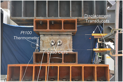
Figure 3. Measurement scheme.
Results
The three specimens, 12 tests in total, were loaded cyclically. Between two tests, there was a 2-h period to wait for the contact surface cooling down automatically to the room temperature.
Time Histories of Friction Forces for S2
The friction force histories, F, of the four tests for specimen S2 with the tightening force of 120 kN are shown in Figures 4A–D corresponding to the loading frequencies 0.02, 0.1, 0.5, and 1 Hz, respectively. At the smaller loading frequencies, 0.02 and 0.1 Hz, there is a small variation in the skeleton curves. After 100 cycles, the maximum force changed by 16.8 and 18.6%, respectively, for the two cases in the positive direction and 20.4 and 5.3% in the negative direction. When the loading frequency increased to 0.5 and 1 Hz, pronounced variation can be observed in the skeleton curves. For the test of 0.5 Hz, it is 50.2% in the positive direction and 49.1% in the negative direction. For the test of 1.0 Hz, they are 52.8 and 50.4% in the positive and negative directions, respectively. A similar phenomenon can be observed for the specimens S1 and S2. The reason behind this will be discussed in the section Friction Coefficient.
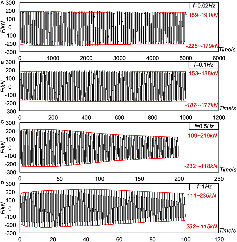
Figure 4. Time histories of friction forces for S2.
Hysteretic Curves
The hysteretic curves for all tests are listed in Figure 5, where the pictures in each row have identical frequency but different tightening forces, while those in each column have the same tightening force but different frequencies. For some tests, the connection bolts were not well fastened, and slippage occurred, such as the four tests of S3 and the test of S1 with a frequency of 0.02 Hz. From the comparison, we can also observe that the force degradation occurred if the loading frequency increased or the tightening force increased. For the tests with a loading frequency of 1 Hz, significant vibration was observed after each unloading–slipping action. One of the possible reasons is that the stuck of the contact surface was suddenly changed and the energy was released abruptly. However, details shall be examined more closely on the microscopy mechanism, which depends on the microscopic real contact area (Ar) and the compatibility of the two sliding materials (Rabinowicz, 1995; Williams, 2005; Khoo et al., 2016). When the loading direction changes, the microscopic real contact area changes, and so does the friction coefficient. Therefore, a large oscillation would occur when unloading. From these curves, the initial stiffness was also measured from each test. Generally, the initial stiffness did not change too much. The averaged initial stiffness is 286 kN/mm and the standard deviation is 11 kN/mm.
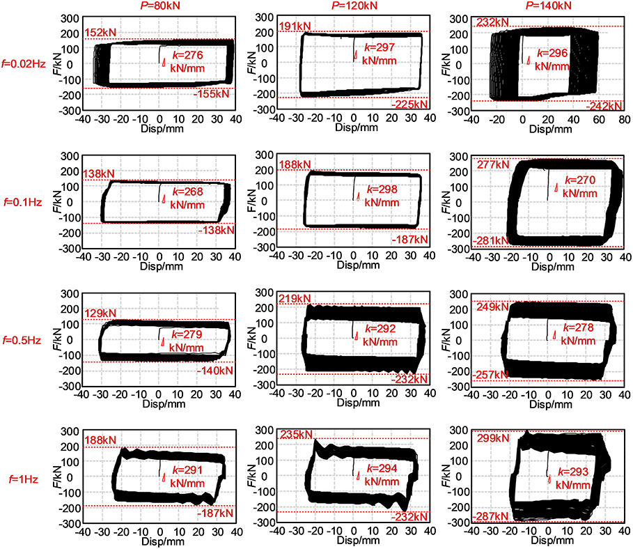
Figure 5. Comparison of hysteretic curves.
Friction Coefficient
To examine the variation of friction coefficient, the friction force corresponding to the maximum velocity or zero displacement is selected and drawn in Figure 6. Generally, the friction coefficients were relatively stable for the smaller loading frequencies such as 0.02 and 0.1 Hz, and significantly degraded for larger frequencies of 0.5 and 1.0 Hz. The temperature histories are also given in Figure 6. The degradation of friction coefficient is correlated with the increase in temperature.
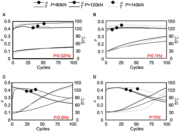
Figure 6. Variation of friction coefficients: (A) f = 0.02 Hz; (B) f = 0.1 Hz; (C) f = 0.5 Hz; (D) f = 1 Hz.
Thermal–Mechanical Model
The friction coefficient is first examined at the room temperature. To avoid potential loading instability in the first cycle, the data obtained from the first three cycles are used. As shown in Figure 7, the friction coefficients for the 12 tests are plotted with respect to the total tightening force. The friction coefficient did not change significantly with the total tightening force. They varied between 0.361 and 0.447, and the averaged value is 0.408. Therefore, at the particular study, the contact pressure dependency can be ignored.
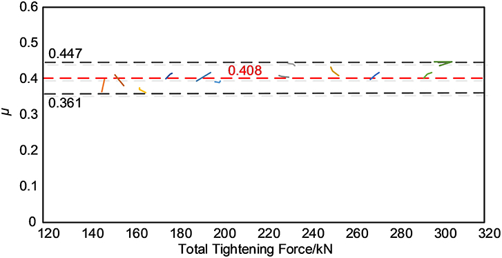
Figure 7. Variation of friction coefficient with respect to total tightening force.
Several studies have regressed the friction coefficient with respect to the pressure, temperature, and the dissipated energy (Kato, 2001; Latour et al., 2014). It is found that the dissipated energy, to some extent, can reflect such micro-mechanism of contact surfaces as progressive wearing and material degradation. The correlation of the friction coefficient with the velocity and the dissipated energy is very appealing because these variables can be easily obtained from the dynamic time history analysis and thus can be directly used in the design procedure.
The force of the friction damper, F, is first written as Equation (1) where P0 is the nominal surface pressure force, and μeff is the effective friction coefficient, which is a function of dissipated energy, Eaccu, and the nominal velocity, v0, defined in Equation (2) where A is the nominal amplitude.
Since the surface pressure or the tightening force has limited influence on the friction coefficient, it is reasonable to take the results of S2 for the recursive analysis and use the results of S1 and S3 for the demonstration. As shown in Figure 8A, the friction coefficient can be expressed as a function of temperature, and the fitting function is adopted as Equation (3), where a, b, c, and d are fitting parameters and T is the measured temperature.
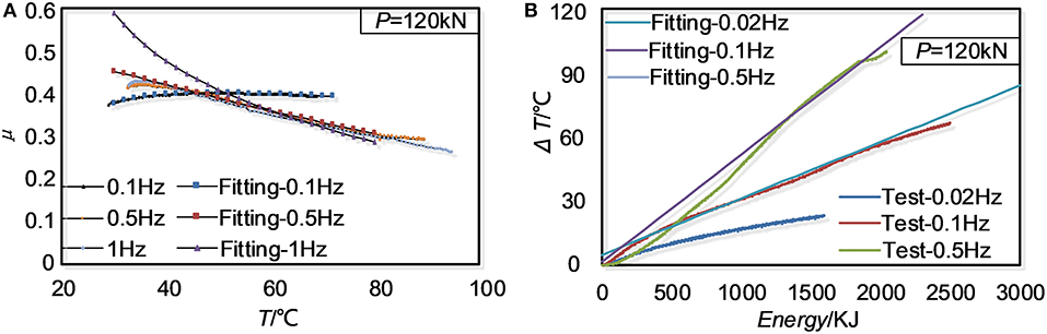
Figure 8. Regression of friction coefficient using S2 data: (A) Friction coefficient related temperature; (B) Temperature incremental related to accumulated energy.
Four sets of parameters [a, b, c, d] can be obtained at different loading frequencies. These parameters, again, can be fitted as the functions of nominal velocity, expressed as Equations (4–7):
where p1 = 0.002518, p2 = 0.3979, p3 = −0.00001, and p4 = 0.000255. According to the thermodyanmics, the increase of temperature ΔT is related to the energy G, as shown in Figure 8B. Similar as the above procedure, Equation (8) can be recursed as:
k and l can be also expressed as the functions of the nominal velocity, as Equations (9, 10):
where q1 = 0.01329, q2 = −0.00555, q3 = −4.984, and q4 = 12.19. Note that the units used during the above regression procedure are kilojoule, centigrade, millimeter, and second.
To demonstrate the effectiveness of the proposed thermo-mechanical model, the above equations are applied for the cases with different tightening forces; the results are shown in Figure 9, and the fitting curve agrees well with the measured data for the S1 case, with all differences <5%. For S3, however, the difference is much larger. The maximum difference is 31%. The reason is that the tightening force was too big for the friction plate, and the plate was damaged during the test. The recommended pressure design value by the “Manual of design and construction for passive-controlled structure” (The Japan Society of Seismic Isolation, 2008) is 5–15 MPa. In the following hybrid coupling beam, the pressure was pre-loaded to 5 MPa.
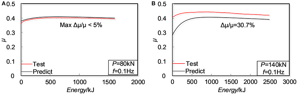
Figure 9. Validation of recursive formula: (A) S1 at loading frequency of 0.1 Hz; (B) S3 at loading frequency of 0.1 Hz.
Hybrid Coupling Beam Installed With Friction Damper
Design of Specimens
The effectiveness of the friction damper is examined experimentally by a substructure test of the coupling beam. Two 2/3 scaled coupling beam specimens were designed: one being a traditional RC coupling beam and the other being a hybrid coupling beam with similar dimensions, as shown in Figures 10A,B, respectively. The span-to-height ratio of the RC specimen is 2, and the thickness of the slab is 70 mm. The scaled coupling beam is 240 mm thick and 675 mm high, with a span of 1,350 mm. The demands of the shear force and bending moment for the scaled model are 425.8 and 134.8 kN, respectively. The design satisfied the concrete design code and the seismic design code of China (MOHURD, 2016a,b). All longitudinal rebars in the coupling beam, boundary elements, wall limbs, slab, diagonal strut, and connection beams were HRB400, while the rest were HRB335. The concrete was C30. When fabricating the specimen, each diagonal strut was replaced by a pair of rebars because of the limited space of the scaled model, and the cover thickness was chosen as 20 mm. The anchorage length was not scaled to avoid bond slippage failure, which was 600 mm. The stiffness was calculated as 420 kN/mm.
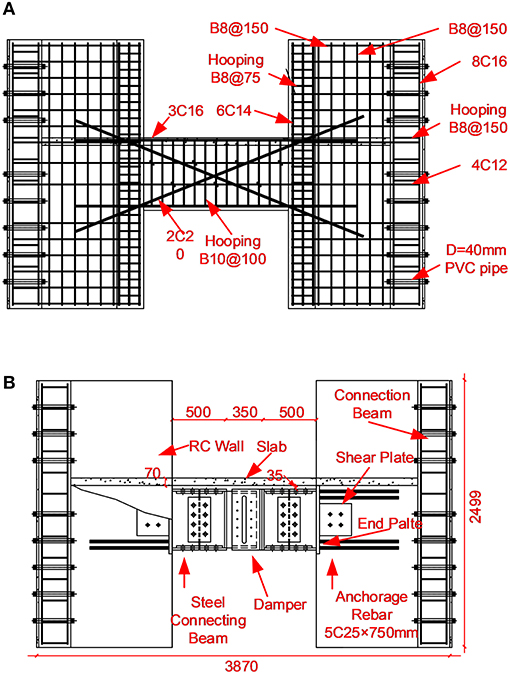
Figure 10. Design of specimen: (A) RC coupling beam; (B) Hybrid coupling beam.
The RC part of the hybrid coupling beam has the same design as the RC coupling beam. The friction damper was placed at the mid-span of the beam. The flanges of the friction damper were modified as the wide flange steel beams and connected the connecting beams with the same cross-section of W570 × 240 × 20 × 20 mm. Grade 10.9 high-strength bolts with a diameter of 20 mm were used to connect the damper to the connecting beams at both flanges and the web. It was supposed that a rigid connection could be realized. The steel connecting beam was welded to an end plate with a thickness of 30 mm. The end plate was embedded into the RC wall through with a 25-mm-thick steel plate to sustain the shear force and five pairs of anchorage rebars to take the bending moment. The anchorage rebars were 25 mm in diameter and 740 mm in length. The damper slip force was taken as 80% of the design value of the RC coupling beam to avoid concrete damage introduced by uncertainties of friction behavior. The connecting beam and the bolt connection were designed using 1.4 times of the damper slip force and the associated bending moment, considering the difference between static and dynamic friction coefficients. The anchor design took 2.0 times the slip force of the damper. All the steel used for the hybrid coupling beam were Q345. The design satisfied the design code of steel structures of China (MOHURD, 2017). It should be noted that the friction damper would concentrate more deformation within a much smaller span than the RC coupling beam. To avoid serious slab damage, the RC slab was separated from the steel coupling beam, and the 35-mm gap was inserted between them. However, to maintain the same architectural requirement of space, the total height of the hybrid coupling beam including the slab was not changed, and the calculated stiffness was similar to the RC coupling beam, with the difference being <5%.
Loading Setup and Measurement Scheme
The loading frame as shown in Figure 11 was used to load the coupling beams. There are four columns and one set of beams to form the loading frame. The specimen was turned 90° for the convenience of loading, and it was securely fastened to the foundation beam, which was further fixed on the strong floor. On the top of the specimen an L-shaped loading beam was attached. The specimen was connected to the foundation beam and the loading beam by high-strength bolts, and the holes of concrete part were filled by high-strength CSV cement. This was specially designed to reduce the potential slippage of the specimen. The right bottom end of the L-shaped loading beam was attached to a 100-ton static actuator. The actuator was displacement controlled following a typical steadily increasing load profile. Several amplitudes were selected as 1/2,000, 1/1,000, 1/800, 1/500, 1/200, 1/120, 1/75, 1/50, and 1/30 of the span of the coupling beam. Two cycles were conducted at each amplitude. On the top of the loading beam, there is a parallelogram mechanism to restrain the rotation on the top of the specimen. Note that the center line of the actuator is through the mid-span of the coupling beam. This will reduce the overturning moment of the entire specimen and the idealized shear-type loading can be achieved.
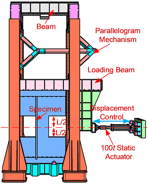
Figure 11. Loading setup.
Similar measurement schemes were adopted for both specimens, as shown in Figure 12. Horizontally, there were six displacement transducers to measure the relative deformations of the overall coupling beam, the connecting beams, and the friction damper. Vertically, there are two displacement transducers to measure the relative rotation between the wall limbs. Diagonally, there are two pairs of diagonal transducers to measure the shear deformation of steel connecting beams and the RC coupling beam. For the hybrid coupling beam, the bending deformations of steel connecting beams were also measured. Together with the transducers, the actuator force was also synchronically measured by using the same data acquisition system.
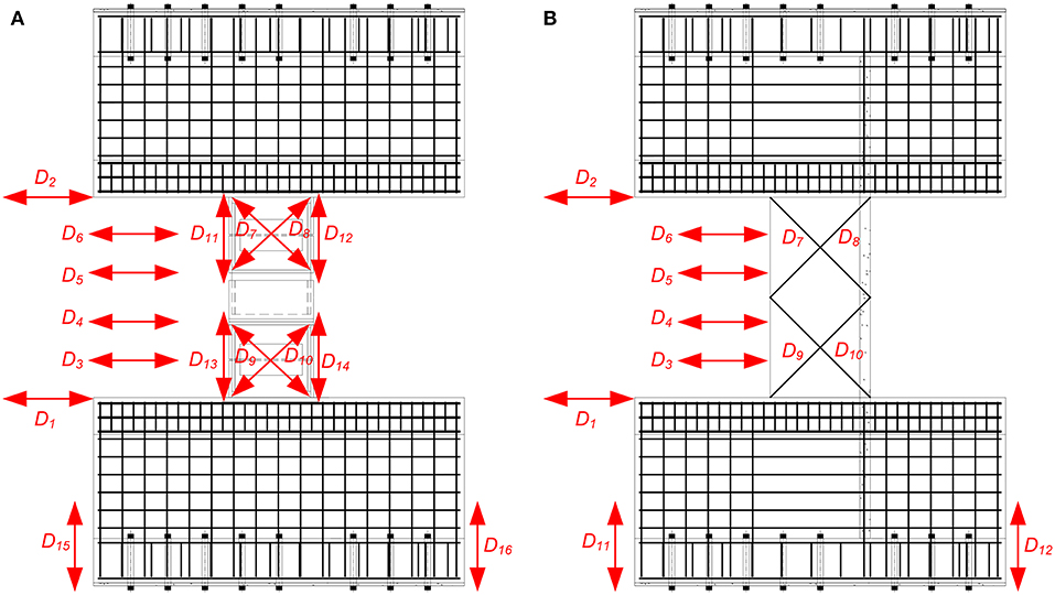
Figure 12. Measurement scheme: (A) RC coupling beam; (B) Hybrid coupling beam.
Discussion of Experimental Results
The RC coupling beam was loaded to an amplitude of 1/30. When loading in the negative direction of the first cycle, the lateral force dropped quickly from 659 to 400 kN. Because a large crack occurred in the RC wall, the loading was stopped. The hybrid coupling beam was also loaded to an amplitude of 1/30. Different from the RC coupling beam, the hybrid coupling beam survived after two cycle loadings, and the bearing force was observed to be quite stable. The loading was stopped because it almost reached the stroke of the actuator.
The hysteretic curves are shown in Figures 13A,B for the RC coupling beam and the hybrid coupling beam, respectively. The peak forces of the RC coupling beam are 648 and −659 kN, respectively, in the positive and negative directions. However, the design force was 426 kN. The over-strength ratio is about 1.5, which cannot be predicted without real loading. The hybrid coupling beam performed very stably. The maximum forces are 348 and −298 kN in the positive and negative direction, respectively. Due to the asymmetry of the loading device, the forces in the positive and negative directions are inconsistent, and the curve is asymmetrical. Considering the design value, 341 kN, the maximum difference is 12.6%. The hysteretic curve of the friction damper is also given in Figure 13B. It can be observed that most energy was dissipated by the damper.
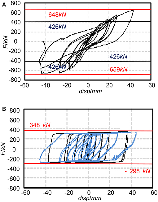
Figure 13. Hysteretic curves: (A) RC coupling beam; (B) Hybrid coupling beam.
As plotted in Figure 14, the deformation of coupling beam (D2 – D1) is compared with the deformation of damper (D5 – D4). At an amplitude smaller than 1/120, the friction damper almost did not move. At this stage, a large stiffness is helpful to limit the horizontal deformation of a building. With the loading increasing, at an amplitude of 1/120, the damper took larger than 50% of the overall deformation, and it took more than 80% deformation at an amplitude of 1/30. On the one hand, the damper dissipated more energy and the lateral response would be reduced. On the other hand, the deformation of the primary structure decreased, and the damage would be mitigated. As shown in Figure 15, the RC coupling beam suffered significant damage in the coupling beam and the wall. The longest crack was over 1 m and the maximum width was larger than 20 mm. It is very difficult to repair. The RC part of the hybrid coupling beam, however, was damaged slightly. The width of the largest crack was <0.2 mm. Upon unloading, the crack closed. It almost did not have any effect and was thus deemed repair-free or seismic-resilient.
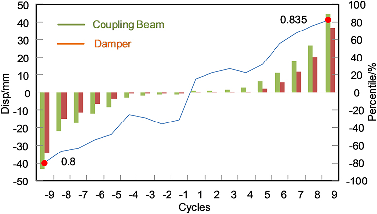
Figure 14. Proportional deformation of dampers over the total lateral deformation.
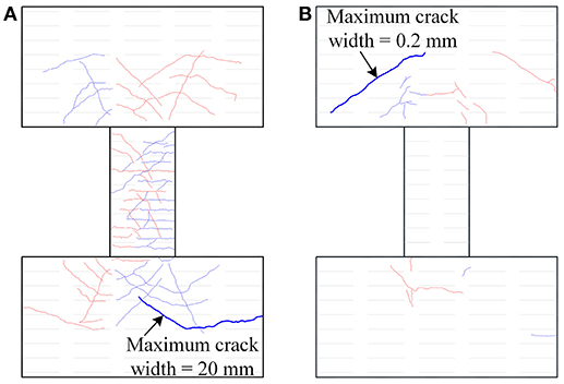
Figure 15. Comparison of crack patterns: (A) RC coupling beam; (B) Hybrid coupling beam.
Conclusions
This study proposed a hybrid coupling beam installed in a friction damper using semi-steel friction material. Damage controllability and energy dissipation capacity are significantly improved. To comprehensively demonstrate its effectiveness, a set of experiments on the damper and the hybrid coupling beam were conducted quasi-statically and cyclically. The major findings are as follows:
(1) Significant temperature-dependent behavior was observed on the friction damper. Although at the smaller loading rate, the damper behaved quite stable, force degradation was observed at the faster loading. When the loading rate is slow, the heat generated by the friction radiates quickly to the surrounding environment, and the temperature will not significantly increase. However, if the loading rate is very high, the heat accumulates in the damper, and the physical characteristics of the contact surface change, then the friction coefficient drops.
(2) A practical thermo-mechanical model was regressed from the test data. The nominal surface pressure was used, and the friction coefficient was related to the energy and speed that can be obtained directly from the time history analysis. However, the physical meaning of some parameters is not clear and was calibrated with limited data. The accuracy shall be further improved. Moreover, the parameters are dependent on the configuration of the damper. Before any application, it is necessary to calibrate them through the test.
(3) The proposed hybrid coupling beam is configured with steel connecting beams, embedded steel plates, and a friction damper. All connection parts shall be designed considering the over-strength introduced by the friction coefficient variation. In this study, the connections worked well without any premature failure. The proposed hybrid coupling beam using a friction damper performed a larger energy dissipation capacity and better damage controllability than the traditional RC coupling beam.
The experimental results are reported in this study together with the thermo-mechanical model developed for the friction damper. However, this is a preliminary study. More studies are required to provide a theoretical basis for the thermo-mechanical model that needs to be further extensively examined. Moreover, the application of the thermo-mechanical model in the numerical analysis shall be elaborated, and the design procedures need to be developed. These issues will be resolved in future studies.
Data Availability
The raw data supporting the conclusions of this manuscript will be made available by the authors, without undue reservation, to any qualified researcher.
Author Contributions
TW developed the hybrid coupling beam and set up the test program. FY conducted the two tests on hybrid coupling beam. XW conducted the tests on dampers. YC developed the thermo mechanical model of the damper.
Funding
This work was supported by the National Key Research and Development Program of China (2017YFC1500701), the Scientific Research Fund of Institute of Engineering Mechanics, CEA (2017A02), and the National Natural Science Foundation of China (51378478 and 51678538).
Conflict of Interest Statement
The authors declare that the research was conducted in the absence of any commercial or financial relationships that could be construed as a potential conflict of interest.
References
Ahn, T. S., Kim, Y. J., and Kim, S. D. (2013). Large-scale testing of coupled shear wall structures with damping devices. Adv. Struct. Eng. 16, 1943–1955. doi: 10.1260/1369-4332.16.11.1943
Aiken, I. D., Nims, D. K., Whittaker, A. S., and Kelly, J. M. (1993). Testing of passive energy dissipation system. Earthquake Spectra 9, 335–370. doi: 10.1193/1.1585720
Cavallaro, F. G., Latour, M., Francavilla, B. A., Piluso, V., and Rizzano, G. (2018). Standardized friction damper blot assemblies time-related relaxation and installed tension variability. J. Constr. Steel Res. 141, 145–155. doi: 10.1016/j.jcsr.2017.10.029
Cheng, M. Y., Fikri, R., and Chen, C. C. (2015). Experimental study of reinforced concrete and hybrid coupled shear wall systems. Eng. Struct. 82, 214–225. doi: 10.1016/j.engstruct.2014.10.039
Filiatrault, A., Tremblay, R., and Kar, R. (2000). Performance evaluation of friction spring seismic damper. J. Struct. Eng. ASCE 126, 491–499. doi: 10.1061/(ASCE)0733-9445(2000)126:4(491)
Fortney, P. J., Shahrooz, B. M., and Rassati, G. A. (2007). Large-scale testing of a replaceable “fuse” steel coupling beam. J. Struct. Eng. ASCE 133, 1801–1807. doi: 10.1061/(ASCE)0733-9445(2007)133:12(1801)
Gurunath, P. V., and Bijwe, J. (2007). Friction and wear studies on brake-pad materials based on newly developed resin. Wear 263, 1212–1219. doi: 10.1016/j.wear.2006.12.050
Jang, H., Ko, K., Kim, S. J., Basch, S. J., and Fash, J. W. (2004). The effect of metal fibers on the friction performance of automotive brake friction materials. Wear 256, 406–414. doi: 10.1016/S0043-1648(03)00445-9
Ji, X. D., Wang, Y., Ma, Q., and Okazaki, T. (2017). Cyclic behavior of replaceable steel coupling beams. J. Struct. Eng. ASCE 143, 231–241. doi: 10.1061/(ASCE)ST.1943-541X.0001661
Kato, N. (2001). Effect of frictional heating on pre-seismic sliding: A numerical simulation using a rate-, state- and temperature-dependent friction law. Geophys. J. Int. 147, 183–188. doi: 10.1046/j.0956-540x.2001.01531.x
Khoo, H. H., Clifton, C., Butterworth, J., MacRae, G., and Ferguson, G. (2016). Influence of steel shim hardness on the Sliding Hinge Joint performance. J. Constr. Steel Res. 72, 119–129. doi: 10.1016/j.jcsr.2011.11.009
Latour, M., Piluso, V., and Rizzano, G. (2014). Experimental analysis on friction materials for supplemental damping devices. Constr. Build. Mater. 65, 159–176. doi: 10.1016/j.conbuildmat.2014.04.092
Lee, C. H., Ryu, J., Oh, J., Yoo, C. H., and Ju, Y. K. (2016). Friction between a new low-steel composite material and milled steel for SAFE dampers. Eng. Struct. 122, 279–295. doi: 10.1016/j.engstruct.2016.04.056
Loo, Y. W., Quenneville, P., and Chouw, N. (2014). A new type of symmetric slip-friction connector. J. Constr. Steel Res. 94, 11–22. doi: 10.1016/j.jcsr.2013.11.005
Lu, X. L., Chen, Y., and Jiang, H. J. (2013). Experimental study on seismic behavior of “Fuse” of replaceable coupling beam. Nat. Sci. 41, 1318–1325. doi: 10.3969/j.issn.0253-374x.2013.09.007
Mao, C. X., Wang, Z. Y., and Zhang, L. Q. (2012). “Seismic performance of RC frame-shear wall structure with novel shape memory alloy dampers in coupling beams,” in 15 WCEE, Paper ID: 4988, Lisbon. doi: 10.1117/12.917304
Ministry of Housing and Urban-Rural Development of the People's Republic of China (MOHURD) (2016a). Code for Seismic Design of Buildings (GB 50011-2016). Beijing: China Architecture and Building Press.
Ministry of Housing and Urban-Rural Development of the People's Republic of China (MOHURD) (2016b). Code for Design of Concrete Structures (GB 50010-2016). Beijing: China Architecture and Building Press.
Ministry of Housing and Urban-Rural Development of the People's Republic of China (MOHURD) (2017). Code for Design of Steel Structures (GB 50017-2016). Beijing: China Architecture and Building Press.
Montgomery, M. S., and Christopoulos, C. (2015). Experimental validation of viscoelastic coupling dampers for enhanced dynamic performance of high-rise buildings. J. Struct. Eng. ASCE 141:04014145. doi: 10.1061/(ASCE)ST.1943-541X.0001092
Mualla, H. I., and Belev, B. (2002). Performance of steel frames with a new friction damper device under earthquake excitation. Eng. Struct. 24, 365–371. doi: 10.1016/S0141-0296(01)00102-X
Pall, A. S., and Marsh, C. (1982). Response of friction damped braced frames. ASCE J. Struct. Div. 108, 1313–1323.
Teng, J., Ma, B. T., Li, W. H., Zhang, H., and Cao, D. X. (2010). Pseudo-static test for coupling beam damper of coupled shear wall structure. J. Build. Struct. 31, 92–100. doi: 10.14006/j.jzjgxb.2010.12.012
The Japan Society of Seismic Isolation (2008). Manual of Design and Construction for Passive-Controlled Structure. Tokyo, 527-−530.
Wang, Y. Y. (2008). Lessons learnt from building damages in the Wenchuan earthquake: seismic concept design of buildings. J. Build. Struct. 29, 20–25.
Williams, J. A. (2005). Engineering Tribology. New York, NY: Cambridge University Press. doi: 10.1017/CBO9780511805905
Xu, Y. L., and Ng, C. L. (2008). Seismic protection of a building complex using variable friction damper: experimental investigation. J. Eng. Mech. ASCE 134, 637–649. doi: 10.1061/(ASCE)0733-9399(2008)134:8(637)
Xu, Z. D. (2007). Earthquake mitigation study on viscoelastic dampers for reinforced concrete structures. J. Vib. Control 13, 29–45. doi: 10.1177/1077546306068058
Xu, Z. D., Liao, Y. X., Ge, T., and Xu, C. (2016). Experimental and theoretical study on viscoelastic dampers with different matrix rubbers. J. Eng. Mech. ASCE 142:04016051. doi: 10.1061/(ASCE)EM.1943-7889.0001101
Ye, L. H., Qu, Z., He, S. W., Zhu, W. C., and Hou, H. T. (2018). Experimental study on uniaxial mechanical properties of brake pad-type friction damper. China Civil Eng. J. 51, 70–75. doi: 10.15951/j.tmgcxb.2018.07.008
Keywords: hybrid coupling beam, friction damper, damage controllability, friction coefficient, temperature dependency
Citation: Wang T, Yang F, Wang X and Cui Y (2019) Experimental Study on a Hybrid Coupling Beam With a Friction Damper Using Semi-steel Material. Front. Mater. 6:135. doi: 10.3389/fmats.2019.00135
Received: 01 March 2019; Accepted: 24 May 2019;
Published: 09 July 2019.
Edited by:
Yong Lu, University of Edinburgh, United KingdomReviewed by:
Wei He, Anhui University of Science and Technology, ChinaJiafei Jiang, Tongji University, China
Copyright © 2019 Wang, Yang, Wang and Cui. This is an open-access article distributed under the terms of the Creative Commons Attribution License (CC BY). The use, distribution or reproduction in other forums is permitted, provided the original author(s) and the copyright owner(s) are credited and that the original publication in this journal is cited, in accordance with accepted academic practice. No use, distribution or reproduction is permitted which does not comply with these terms.
*Correspondence: Tao Wang, d2FuZ3Rhb0BpZW0uYWMuY24=