 Ying-Qing Guo
 Yang Li1
 Tian-Tian Yang
 Xingjian Jing
- 1Mechanical and Electronic Engineering College, Nanjing Forestry University, Nanjing, China
- 2Department of Mechanical Engineering, The Hong Kong Polytechnic University, Hong Kong, China
- 3Nanjing Dongrui Damping Control Technology Co., Ltd, Nanjing, China
- 4Faculty of Civil Engineering and Mechanics, Jiangsu University, Zhenjiang, China
The viscoelastic material is one of most popular shock absorbing materials for mitigating vibrations of building structures due to earthquake. Its dynamic performance is affected by the temperature, the excitation frequency and the excitation amplitude. Therefore, in order to study the non-linear dynamic performance of the viscoelastic materials, a hybrid test system using the electric exciter is proposed, in which the electric exciter is the actuator, MATLAB is used for the simulation of the numerical substructure and the communication between the upper computer and the lower machine, and STM32 single-chip microcomputer is used to control the work state of the electric exciter. Based on the equivalent force control method and the incremental PID control algorithm, a controller is designed to make sure the electric exciter produces accurate control forces to the non-linear test component in the physical substructure. It can be shown from the test results that the developed whole hybrid test system is feasible and effective.
Introduction
In the process of the research of the structural dynamic performance induced by different earthquake, sometimes the core materials or components of the whole structure have very strong non-linearities and unknown properties, which accurate mathematical model cannot be obtained, at the same time, the structure is some kind of large-scale structures, so how to analysis the effect or functions of the core components and the whole structural dynamic performance? Hybrid Test, also called as on-line experiment (Hakuno et al., 1969; Takanashi et al., 1975) is an innovation experimental testing method. Hybrid Test mainly includes two parts: one part is the physical test for the core components of the whole structure; the other part is the numerical simulation for the rest of the whole structure. These two parts are be effectively combined to realize the evaluation of the dynamic performance of the structure and components.
Since the twenty-first century, with the advent of large-scale and complex structures, the hybrid test is developing in two directions: In the spatial domain, in order to integrate the experimental resources from different regions, the hybrid test is developed from local partial tests to network collaborative tests (Mosqueda et al., 2008); In the time domain, in order to test the velocity -dependent specimen, the hybrid test is developed from the rapid test in reality to the real-time test in the ideal (Nakashima, 2001). In 2004, Pearlman et al. (2004) arranged physical substructures and numerical substructures at the University of Colorado and the University of Illinois, respectively, the communication between the upper and lower machines relied on the network, which is a bold attempt to the division and location restrictions of physical substructures and numerical substructure of the hybrid test. In 2005, Pan et al. (2005) developed an Internet online test system which physical test and associated numerical analysis were different location, and the two locations communicate over the Internet. In 2006, Takahashi and Fenves (2006) developed an object-oriented software framework for distributed experimental-computational simulation of structural systems. And they carried out a distributed pseudo-dynamic test using a client-server approach, in which the server program controlled the test equipment in Japan and the client program performed the computational simulation in the United States. In 2009, Carrion et al. (2009) presented an approach for real-time hybrid simulation in which compensation for actuator dynamics was implemented using a model-based feed forward compensator. In 2012, Saouma et al. (2012) developed a specialized software written explicitly to perform, single site, hybrid simulation ranging from pseudo-dynamic to hard real time ones to improve the computational engine of the hybrid test. Chen et al. (2012) presented a real-time hybrid simulation system which included the hydraulic actuators, the IT control architecture, an integration algorithm, and actuator delay compensation. The integration algorithm provided a robust and accurate solution to the equations of motion, and the adaptive inverse compensation method ensured the accurate application of the command displacements to experimental substructure(s) by servo-hydraulic actuators. In 2013, Gao et al. (2013) proposed and validated an H loop shaping design for actuator motion control in real-time hybrid simulation to improve both the stability limit and test accuracy compared with several existing strategies. Furthermore, the feature of the strategy was its robust performance in terms of unmodeled dynamics and uncertainties. In 2016, Na and Kim (2016) developed a non-linear finite element analysis program for hybrid, in which the fixed number iteration method and parallel computational technique was used to shorten the computational time. And, in the real-time control system, the inter-communication between a substructure and an analysis program was simplified. In 2017, Fermandois and Spencer (2017) presented a framework for multi-axial real-time hybrid simulation, which consisted in prescribing multiple degrees-of-freedom at the interface between numerical and experimental substructures by using a multi-actuator loading assembly. The multi-axial real-time hybrid simulation was carried out for a single-story building structure. Xu et al. (2017) developed a hybrid dynamic test system based on electro dynamic fatigue test machine. In this hybrid test system, the electro dynamic fatigue test machine was used as the actuator, simulation program was made based on MATLAB which was easy to modify and debug in accordance with the real test's requirements; the high-performance STM32 single-chip microcomputer was used as the core control chip.
The viscoelastic material is one of most popular shock absorbing materials for mitigating vibrations of building structures due to earthquake (Xu et al., 2019). Its dynamic performance is affected by the temperature, the excitation frequency and the excitation amplitude. This paper presents a hybrid test system to study the non-linear dynamic performance of the viscoelastic materials. In the hybrid test system, the electric exciter is the actuator, MATLAB is used for the simulation of the numerical substructure and the communication between the upper computer and the lower machine, and STM32 single-chip microcomputer is used to control the work state of the electric exciter. Based on the equivalent force control method and the incremental PID control algorithm, a controller is designed to make sure the electric exciter produces accurate control forces to the non-linear test component in the physical substructure. The whole hybrid test system is tested, and the viscoelastic damper adopted as the non-linear test component. The test results show that the developed whole hybrid test system is feasible and effective.
Design Scheme of Hybrid Test System
The hybrid test system using the electric exciter mainly includes two parts: the upper computer and the lower machine (that is the physical substructure), as shown in Figure 1. In the upper computer, MATLAB is used to write the numerical substructure program and the communication program between the upper computer and the lower machine. The numerical substructure program will realize the modeling and simulation of the numerical substructure. Through the communication program, the upper computer can send the command signals to the lower machine, and accept the displacement or the force signals transmitted by the lower machine. The lower machine, the physical substructure, mainly includes the non-linear test component, the controller, the electric exciter and sensors. The controller takes STM32 single-chip microcomputer as the main controller to write the serial communication program of the upper and the lower machine, the electric exciter control program and sensors data acquisition procedure.
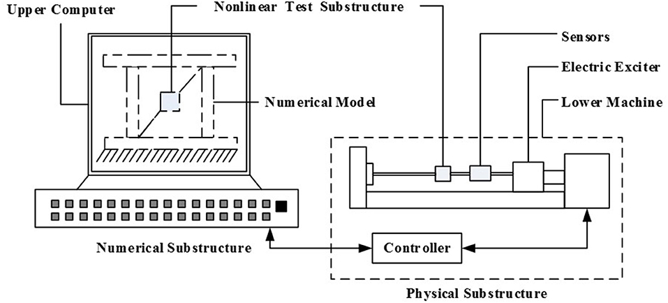
Figure 1. The hybrid test system.
Figure 2 shows the detail design scheme diagram of the hybrid test system. The electric exciter is as the actuator (that is, the power source of the whole system) to realize the loading of the vibration force of the non-linear test component. The STM32 single-chip microcomputer is as the core control chip to realize the data communication between the upper computer and the lower machine, the data collection of the sensors and the drive control of the exciter by using the PID controller. MATLAB is used to complete the modeling and simulation of the numerical substructure and the data communication of the upper computer and the lower machine. Serial communication mode is adopted to realize the real-time two-way communication between STM32 single-chip microcomputer and MATLAB in the upper computer, and to establish the relationship between the numerical substructure and the physical substructure.
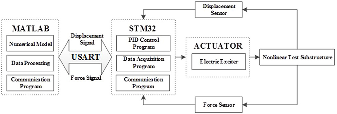
Figure 2. The detail design scheme diagram of the hybrid test system.
Design of the Hybrid Test System Controller
In this paper, the electric exciter is as the actuator, which works on the non-linear test component according to the control signal coming from the upper computer. Here the viscoelastic damper is chosen as the non-linear test component. In order to make the electric exciter to produce accurate control forces, the equivalent force control method and the incremental PID control algorithm are used at the same time, as shown in Figure 3.
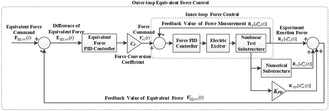
Figure 3. Equivalent force control schematic diagram.
Equivalent Force Control Method
For the electric exciter, its control current is linear with the force it produces. While the test component is non-linear, the equivalent force control method (Wu et al., 2007; Bursi et al., 2008) is used to determine the control signal of the electric exciter. The equations of motion, the expressions of the displacement and the velocity in discrete time are as follows:
Where, M and C are the mass matrix and the damping matrix of the structure, respectively, which usually are constants; RN is the reaction force vector of the numerical substructure; RE is the reaction force vector of the non-linear test component; i is the time step; di, vi, ai are the displacement, the velocity and the acceleration, respectively; Δt is the integral time interval; F is the external load vector.
According to Equations (2, 3), the speed and the acceleration of step i+1 can be described as:
Substitute Equations (4, 5) into Equation (1):
KPD is a pseudo-stiffness matrix. FEQ, i+1 is the equivalent force for each load cycle, which consists of two parts, the external excitation force Fi+1 in the current loading cycle and the pseudo-dynamic effect calculated according to the displacement response in this period. Equation (6) is a non-linear equation about the displacement variable di+1, which can also be regarded as an equilibrium equation about the equivalent force FEQ, i+1. Meanwhile it can be seen from Equation (6) that the left side of the equation is added by the damping force RNdi+1 of the numerical substructure, the pseudo-dynamic KPDdi+1 and the experimental reaction force REQdi+1 of the non-linear test component,and the right side of the equation can be regarded as the equivalent external force FEQ, i+1. So the solution of the equation is the displacement di+1 of the effect system under the influence of equivalent external force.
The equivalent force control method uses a closed-loop control system, that is, a feedback control method,the control method makes the feedback force [left side of Equation (6)] equal to the equivalent force [right side of Equation (6)]steadily and asymptotically, as shown in Figure 3. In each integral time interval Δt, with the equivalent force controller and the force conversion coefficient C F, the equivalent force difference EEQ, i+1(t) between the equivalent force command FEQ, i+1(t) and the equivalent force feedback value obtain the next force command . At the end of each loading cycle, when the equivalent force feedback value can infinitely approximate the equivalent force F EQ, i+1(t) command in corresponding to the loading cycle, the actual displacement will be infinitely close to the target displacement di+1(t) and will become the solution of Equation (6). By the solution of Equation (6), the exciter outputs a corresponding displacement, which in turn produces equivalent force. Among them, CF is the force distribution coefficient, its effect is equivalent to Newton iterative method in the Jacobian matrix, the value of the force distribution coefficient CF is as follows:
Where, KN and KE are the initial stiffness matrices of the numerical substructure and the non-linear test component respectively.
Design of the Incremental PID Controller
The function of the controller is enabling the equivalent force feedback value track the equivalent force command accurately, the controller is divided into the inner-loop force controller and the outer-loop equivalent force controller. The outer-loop controller is equal-effect control to calculate the force loading command of the electric exciter by the force distribution coefficient. The inner-loop controller is the force control of the electric exciter, so that the electric exciter can accurately reach the force command. The PID controllers are adopted as these two controllers.
In the control system involving computer technology, most of the traditional analog PID cannot be used successfully, because the computer cannot perform integral or differential operation directly,computers can only be simulated infinitely to approach this mathematical calculation in other ways. On the other hand, in the single-chip microcomputer technology, the signal acquisition is also discrete, only can collect signal for feedback periodically through the signal acquisition module. Digital PID algorithm is divided into two kinds, the incremental PID algorithm and the position PID algorithm. The position PID algorithm directly produces the final output of the system in each control period, which is a relatively direct control method. But in this approach, each of the previous errors are accumulated, and the entire system is closely linked before and after each adjustment cycle. It can easily lead to excessive adjustment of the amplitude, and even cause serious control accidents. The incremental PID algorithm converts the analog signal into a digital signal, which is convenient for computer calculation and the single-chip acquisition. On the other hand, compared with the position PID algorithm, the incremental PID algorithm has a smaller calculation, which can guarantee the reliability and real-time performance of the system. Therefore, the incremental PID controller is chosen, and the discrete incremental PID algorithm is as follows:
Where, u(k) is the output of the k-th sampling period of the control system, and e(k) is the input deviation of the k-th sampling period of the control system; KP is the proportional coefficient of the control system; Ti is the integral time constant of the control system; Td is the differential time constant of the control system; and T is the system sampling period. According Equation (10) the output value of the k-1-th sampling cycle is:
The each adjustment cycle output of the incremental PID controller is the increment of adjustment on the basis of the first 2 times adjustment cycles, so by subtracting Equation (11) from Equation (10), the output equation of the incremental PID controller can be obtained:
Where, .
Simulation Model of System
According to the above principle of equivalent force control, the Matlab/Simulink simulation model of the equivalent force control system of the hybrid test system is shown in Figure 4. In the hybrid test system there are two PID controllers, an inner-loop force PID controller and an outer-loop equivalent force PID controller. The “Subsystem” block includes the electric exciter model and the inner-loop force PID controller. The input of the inner-loop force PID controller is the difference between the target force and the actual force, and the output is the control value of the electric exciter. The function of the outer-loop equivalent force PID controller is “forcing” the motion Equation (6) of the hybrid test system to be established to ensure the stability and accuracy of the whole hybrid test system. And its input is the difference of equivalent force.
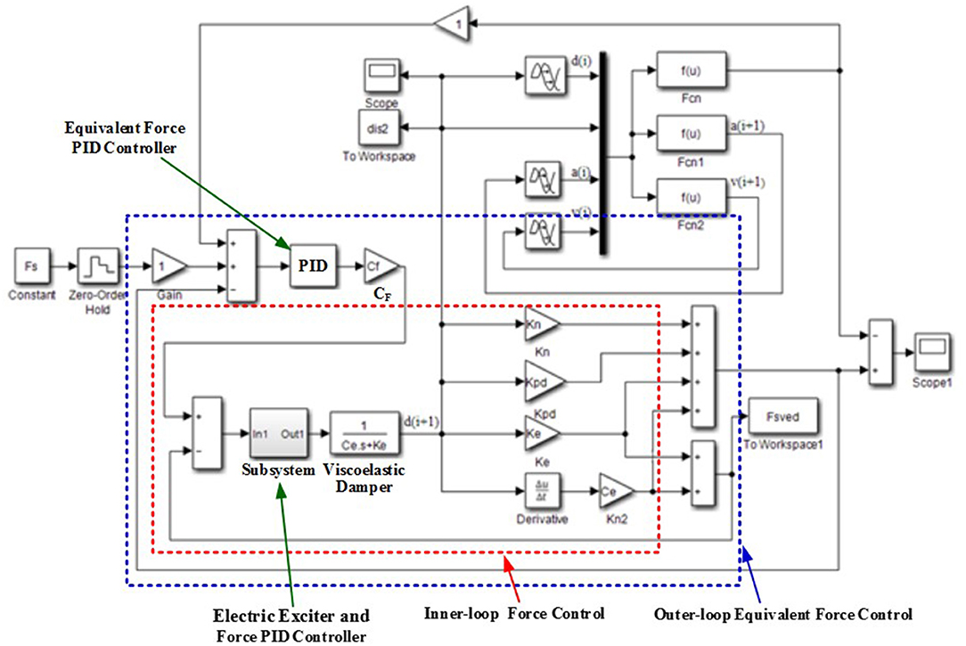
Figure 4. Simulink simulation model of the equivalent control system.
In the simulation model the viscoelastic damper is chosen as the non-linear test component, and its transfer function is:
Where Ce is the equivalent damping of the viscoelastic damper and Ke is the equivalent stiffness of the viscoelastic damper. According to the basic theory of the viscoelastic damper, its parameters can be obtained. The shear modulus is:
The loss factor is:
The loss modulus is:
The equivalent stiffness is:
The equivalent damping is:
Where n is the number of layers of the viscoelastic damping material, A is the shear area of viscoelastic damping material layer, h is the thickness of the viscoelastic damping material layer; u0 is the maximum displacement of the viscoelastic damper in horizontal direction; F0 is the maximum damping force of the viscoelastic damper; F1 is the damping force at the maximum displacement of the viscoelastic damper; F2 is the damping force at zero displacement of the viscoelastic damper; ω is the loading circular frequency.
Test Analysis
The test device of the hybrid test system designed in this paper is shown in Figure 5. The physical substructure is mainly composed of the electric exciter, the force sensor, the displacement sensor, the viscoelastic damper and STM32 controller. The specific model of the electric exciter is KDJ100. Its maximum exciting force is 1,000 N, its maximum amplitude is ±15 mm and its maximum current is 30A. A plate viscoelastic damper is used as the non-linear component in the hybrid test system, which consists of an intermediate steel plate, two constrain steel plates and two pieces of viscoelastic material, as shown in Figure 6. For each piece of viscoelastic material, its area is 20 × 25mm, and its thickness is 8 mm. The thickness of all steel plates is 7 mm. The damping of the viscoelastic damper Ce = 5KN·s/m, the stiffness of the viscoelastic damper Ke = 200 KN/m. Three sets different sinusoidal signals are used to tests the physical substructure. El-Centro earthquake wave and Tianjin earthquake wave are used as the excitation signals of the whole hybrid test system.
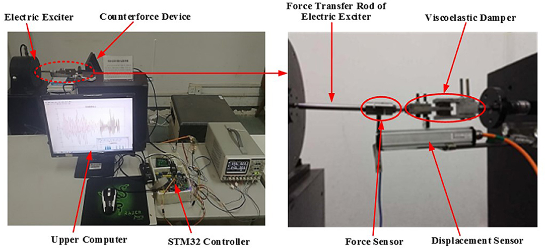
Figure 5. The test device of the hybrid test system.
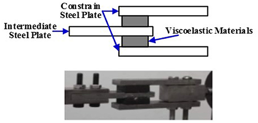
Figure 6. The viscoelastic damper.
Before testing the performance of the whole hybrid test system, the dynamic performance of the physical substructure is tested firstly. Three sets of sinusoidal signals with the same frequency and different amplitudes are used as the control signals of the electric exciter, which will make the electric exciter to produce the frequencies of the forces all are 5 Hz, and the amplitudes of the forces are 5, 100, and 150 N, respectively. Under these three sets of the forces the force-displacement relationship of the viscoelastic damper are detected by using the force sensor and the displacement sensor in the hybrid test system, and then the results are shown in Figure 7. It can be seen that at the same loading frequency, with the increase of the force amplitude, the inclination angle of hysteretic curves of the viscous damper decreases, the envelope area increases, that is, the equivalent stiffness of the viscoelastic damper decreases with the increase of the force amplitude, and the energy dissipation capacity increases with the increase of the force amplitude. Meanwhile, it can be obtained that the physical substructure of the hybrid test system can work normally, and the non-linear component, the viscoelastic damper, has strong non-linearity and good energy dissipation characteristics.
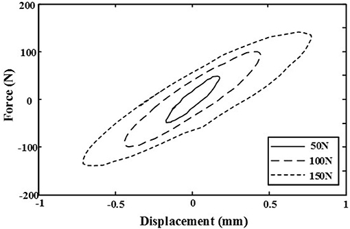
Figure 7. Force-displacement hysteretic curve of the viscoelastic damper.
El-Centro earthquake wave and Tianjin earthquake wave are used as the excitation signals of the whole hybrid test system to test its performance. Under different earthquake wave excitation, the output forces of the electric exciter collected in real-time are compared with expected output forces, as shown Figure 8. It can be seen from Figure 8 that whether under El-Centro earthquake wave or under Tianjin earthquake wave, the forces applied to the viscoelastic damper by the electric exciter is in good agreement with the expected forces of theoretical analysis, only there is a certain error at the individual point. Under El-Centro earthquake wave, the maximum force produced by the electric exciter is 191 N, the maximum expected value of the theoretical analysis is 200 N. The absolute error is 9 N and the relative error is 4.5%. The maximum error occurs at the 300th data point, where the experimental value is 141 N and the expected value is 160 N. And the absolute error is 19 N, the relative error is 11.9%. Under Tianjin earthquake wave, the maximum force produced by the electric exciter is 275 N, the maximum expected value of the theoretical analysis is 285 N. The absolute error is 10 N and the relative error is 3.5%. The maximum error appears at the 624th data point, the experimental value is 218 N and the expected value is 250 N. The absolute error is 32 N and the relative error is 12.8%. The main reason for these errors is that the viscoelastic damper is a kind of non-linear damping device, especially the viscoelastic material used in the device has strong non-linear characteristics which dynamic performance is affected by the temperature, the excitation frequency and the excitation amplitude (Xu et al., 2016). In the theoretical analysis, the model parameters of the viscoelastic damper are obtained by analyzing the data of its performance experiment. Within the allowable range of error, these model parameters of the viscoelastic damper can meet the requirements of most excitation frequency and excitation amplitude, but they are fixed values and cannot change with the change of the temperature, the excitation frequency and the excitation amplitude. However, the frequency and the amplitude of El-Centro earthquake wave and Tianjin earthquake wave used in the whole hybrid test system are changed at all times. This causes a certain error between the experimental value and the theoretical value at individual points. In addition, the parameters of the PID controller used in the entire hybrid test system are fixed during the whole test process, so that the control requirements under most excitation can be guaranteed. However, the parameters of the PID controller are not adjusted in real time with the change of the non-linear characteristics of the load, so that the optimal control effect cannot be achieved at individual points in the test process, and a certain error occurs.
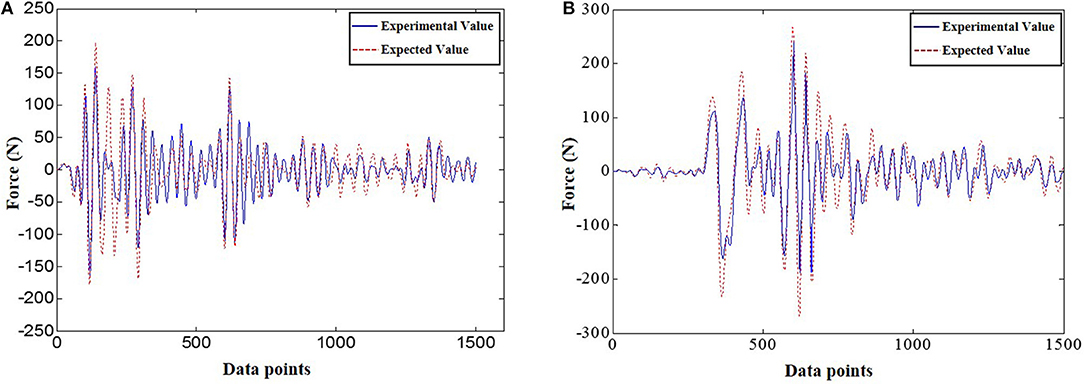
Figure 8. Comparison between experimental value and expected value under different earthquake wave. (A) El-Centro earthquake wave. (B) Tianjin earthquake wave.
Concluding Remarks
In this paper, a hybrid test system is proposed, in which MATLAB is used for the simulation of the numerical substructure and the communication between the upper computer and the physical substructure; the electric exciter is the actuator; STM32 single-chip microcomputer is used to control the work state of the electric exciter; the viscoelastic damper adopted as the non-linear test component; the force sensor and the displacement sensor are used to measure the force and the displacement of the non-linear test component. In order to make the electric exciter to produce accurate control forces to the non-linear test component in the physical substructure, the controller is designed based on the equivalent force control method and the incremental PID control algorithm. The dynamic performance of the physical substructure and the performance of the whole hybrid test system are tested. The test results show that the physical substructure can work normally; the viscoelastic damper has strong non-linearity and good energy dissipation characteristics; and the whole system is feasible and effective.
Data Availability
All datasets generated for this study are included in the manuscript and/or the supplementary files.
Author Contributions
Y-QG proposed the idea of this paper. Under the guidance of Y-QG, YaL, XC, XJ, and YiL finish end the numerical analysis. YaL, T-TY, and XC finished the experiment of the hybrid test system. Y-QG, YaL, T-TY, and XJ jointly completed the writing of the article. YiL helped in proof reading of overall presentation and experimental data.
Conflict of Interest Statement
XC was employed by company Nanjing Dongrui Damping Control Technology Co., Ltd, Nanjing, China.
The remaining authors declare that the research was conducted in the absence of any commercial or financial relationships that could be construed as a potential conflict of interest.
Acknowledgments
The work was supported by The National Key R&D Programs of China with Grant Numbers (2016YFE0119700 and 2016YFE0200500), Jiangsu International Science and Technology Cooperation Program with Grant Number (BZ2018058), the Program of Chang Jiang Scholars of Ministry of Education, Ten Thousand Talent Program of Leading Scientists and the Program of Jiangsu Province Distinguished Professor.
References
Bursi, O. S., Gonzalez-Buelga, A., and Vulcan, L. (2008). Novel coupling rosen brock-based algorithms for real-time dynamic substructure testing. Earthqu. Eng. Struct. Dynam. 37, 339–360. doi: 10.1002/eqe.757
Carrion, J. E., Spencer, B. F. Jr, and Phillips, B. M. (2009). Real-time hybrid simulation for structural control performance assessment. Earthqu. Eng. Eng. Vibrat. 8, 481–492. doi: 10.1007/s11803-009-9122-4
Chen, C., Ricles, J. M., Karavasilis, T. L., Chae, Y., and Sause, R. (2012). Evaluation of a real-time hybrid simulation system for performance evaluation of structures with rate dependent devices subjected to seismic loading. Eng. Struct. 35, 71–82. doi: 10.1016/j.engstruct.2011.10.006
Fermandois, G., and Spencer, B. F. Jr. (2017). Model-based framework for multi-axial real-time hybrid simulation testing. Earthqu. Eng. Eng. Vibrat. 16, 671–691. doi: 10.1007/s11803-017-0407-8
Gao, X., Castaneda, N., and Dyke, S. J. (2013). Real time hybrid simulation: from dynamic system, motion control to experimental error. Earthqu. Eng. Struct. Dynam. 42, 815–832. doi: 10.1002/eqe.2246
Hakuno, M., Shidawara, M., and Hara, T. (1969). Dynamic destructive test of a cantilever beam, controlled by an analog-computer. Trans. Jpn. Soc. Civil Eng. 1969, 1–9. doi: 10.2208/jscej1969.1969.171_1
Mosqueda, G., Stojadinovic, B., Hanley, J., and Sivaselvan, M. (2008). Hybrid seismic response simulation on a geographically distributed bridge model. J. Struct. Eng. 134, 535–543. doi: 10.1061/(ASCE)0733-9445(2008)134:4(535)
Na, O., and Kim, S. (2016). Multi-directional structural dynamic test using optimized real-time hybrid control system. Exp. Techn. 40, 441–452. doi: 10.1007/s40799-016-0047-3
Nakashima, M. (2001). Development, potential, and limitations of real-time online (pseudo-dynamic) testing. Philos. Trans. R. Soc. A Math. Phys. Eng. Sci. 359, 1851–1867. doi: 10.1098/rsta.2001.0876
Pan, P., Tada, M., and Nakashima, M. (2005). Online hybrid test by internet linkage of distributed test-analysis domains. Earthqu. Eng. Struct. Dynam. 34, 1407–25. doi: 10.1002/eqe.494
Pearlman, L., Kesselman, C., Gullapalli, S., Spencer, B. F Jr., Futrelle, J., Ricker, K., et al. (2004). “Distributed hybrid earthquake engineering experiments: experiences with a ground-shaking grid application,” in 13th IEEE International Symposium on High Performance Distributed Computing, Proceedings (Honolulu, HI), 14–23. doi: 10.1109/HPDC.2004.1323474
Saouma, V., Kang, D. H., and Haussmann, G. (2012). A computational finite-element program for hybrid simulation. Earthqu. Eng. Struct. Dynam. 41, 375–389. doi: 10.1002/eqe.1134
Takahashi, Y., and Fenves, G. L. (2006). Software framework for distributed experimental-computational simulation of structural systems. Earthqu. Eng. Struct. Dynam. 35, 267–291. doi: 10.1002/eqe.518
Takanashi, K., Udagawa, K., Seki, M., Okada, T., and Tanaka, H. (1975). Nonlinear earthquake response analysis of structures by a computer-actuator on-line system: part 1: details of the system. Trans. Arch. Instit. Jpn. 229, 77–83. doi: 10.3130/aijsaxx.229.0_77
Wu, B., Wang, Q., and Shing, P. B. (2007). Equivalent force control method for generalized real-time substructure testing with implicit integration. Earthqu. Eng. Struct. Dynam. 39, 1127–1149. doi: 10.1002/eqe.674
Xu, Z. D., Huang, X. H., Xu, F. H., and Yuan, J. (2019). Parameters optimization of vibration isolation and mitigation system for precision platforms using nondominated sorting genetic algorithm. Mechan. Syst. Signal Process. 128:191–201. doi: 10.1016/j.ymssp.2019.03.031
Xu, Z. D., Liao, Y. X., Ge, T., and Xu, C. (2016). Experimental and theoretical study on viscoelastic dampers with different matrix rubbers. J. Eng. Mechan. ASCE 142:04016051. doi: 10.1061/(ASCE)EM.1943-7889.0001101
Keywords: viscoelastic damping material, hybrid test, electric exciter, equivalent force control, incremental PID
Citation: Guo Y-Q, Li Y, Yang T-T, Jing X, Chen X and Luo Y (2019) Design on Hybrid Test System for Dynamic Performance of Viscoelastic Damping Material and Damper. Front. Mater. 6:116. doi: 10.3389/fmats.2019.00116
Received: 29 March 2019; Accepted: 07 May 2019;
Published: 05 June 2019.
Edited and reviewed by:
Abid Ali Shah, University of Science and Technology Bannu, PakistanReviewed by:
Lihua Zhu, Xi'an University of Architecture and Technology, ChinaYanbin Shen, Zhejiang University, China
Copyright © 2019 Guo, Li, Yang, Jing, Chen and Luo. This is an open-access article distributed under the terms of the Creative Commons Attribution License (CC BY). The use, distribution or reproduction in other forums is permitted, provided the original author(s) and the copyright owner(s) are credited and that the original publication in this journal is cited, in accordance with accepted academic practice. No use, distribution or reproduction is permitted which does not comply with these terms.
*Correspondence: Ying-Qing Guo, Z3lpbmdxaW5nQDEyNi5jb20=