- Department of Vehicle Engineering, National Taipei University of Technology, Taipei, Taiwan
Vehicle manufacturers have been attempting to increase engine efficiency and decrease pollution through various methods. Variable valve actuation technology is one of these methods. Several mechanisms have been established already and have been used to develop this technology. However, these systems have common problems such as complex design, large volume, low response rate, and high-energy consumption. In this study, a novel variable valve actuation device that is compact and requires less energy was developed using magnetorheological (MR) fluid technology. The main components used in this device are an MR valve, passive buffer spring, cam, and rocker arm. This study was divided into three parts. First, an MR valve train was designed. This valve train can be constructed easily, and has fewer hydraulic and mechanical components and consumes less energy than other technologies. Second, the magnetic plate block design was optimized to obtain the required control force at optimal volume and energy. Finally, dynamical simulations pertaining to the springs and the structure were executed to analyze the dynamic condition of the valve. The simulation results indicated that the proposed MR valve could effectively provide functions of variable valve timing and variable valve lift (VVL) by dynamically controlling the external current in the magnetic coil.
Introduction
Magnetorheological (MR) fluid is an intelligent fluid that can generate resistance corresponding to variations in a magnetic field. This liquid reacts quickly, can satisfy control operation requirements, and is reversible. MR fluid can be used in numerous types of machinery, such as resistance devices, brakes, and clutches. However, a various problems pertaining to the fluid must be addressed for its effective, practical application (Phu and Choi, 2019). These MR devices operate based on one of the three following resistance conditions—shear, flow, and mixed squeeze and flow resistances. Among these types, flow resistance is a promising concept for realizing intelligent devices for engineering applications. Devices using this concept are available, including dampers, shock absorbers, and MR valves.
Dampers are used in vehicles as shock absorbers for the operation of active and semi active suspension systems. Several mathematical models (Yao et al., 2002), experimental devices, and simulation studies have been achieved. Several studies have revealed the potential of this technology in civil applications by developing an MR damper model (Dyke et al., 1996a,b, 1998). These studies clarify that compared with conventional devices, MR dampers are more effective, active, responsive, and consume less power.
Another flow mode for an MR device is an MR valve that can be used in hydraulic actuation systems. This valve is a valuable alternative to mechanical valves and exhibit many benefits such as low weight, ease of control, and no moving parts. Yoo and Wereley (2002) designed a high-efficiency MR valve with an optimal design. The analyzed its performance and verified it by conducting simulations and experiments. To enhance the performance of an MR valve, numerous MR valve structures have been established, such as a multistage structure, modular structure, and modular structure with meandering flow (Ichwan et al., 2016).
The adoption of this type of intelligent valve control in internal combustion (IC) engines to enhance engine performance is an innovative and valuable research approach. To improve the performance of an IC engine under certain speed and load conditions, the intake quantity and intake timing should be varied continuously (Lee et al., 2007). When suitable valve opening timing and valve lifts are selected, a 6% improvement in engine performance is possible (Sawant and Bari, 2018). Such an improvement cannot be obtained using the conventional cam-based fixed timing valve train control system. Therefore, engine developers have introduced various valve timing (VVT) and variable valve lift (VVL) systems with different actuators. Numerous devices with mechanical, hydraulic, and electronic actuators have been established to achieve such VVT and VVL systems.
Pierik and Burkhard (2000) developed an active mechanical valve and achieved a specific fuel consumption (SFC) improvement of 12% at low-to-medium load conditions. However, this device has drawbacks of a long response time, limited variations, and mechanical frictional elements.Flierl and Klüting (2000) from BMW group proposed electromechanical control that improved SFC by 11%. Sun and He (2007) presented an electrohydraulic valve circuit. However, the circuit requires considerable energy resources and has hydraulic fluid leakage problems. For MultiAir of FIAT, Bernard et al. (2009) used a hydraulic chamber as a clutch between the camshaft and valve. However, the structure of this system is complicated. Shiao and Dat (2013) proposed an electromagnetic valve device for a camless spark-ignition engine. All these devices have specific advantages and disadvantages. However, the common problems of the systems include mechanism complexity and high-energy consumption.
Therefore, this study aimed to fabricate a new valve train device by using the MR fluid technology, which can overcome those problems. It is hoped that the conventional valve-actuating mechanisms can be replaced with an intelligent MR-fluid-based valve to improve IC engine performance. The application of an MR valve in an IC engine is a novel concept. Recently, Smith (2018) invented an electromechanical hydraulic valve lifter based on MR technology for use in an IC engine.
A previous study by the author (Shiao and Cheng, 2016) introduced a new innovative valve device to realize this variable valve actuator, that is, the MR valve (MRV). This is a novel concept for IC engine valve actuation. The valve device has an active block, a magnetic plate block, and a buffer block. The viscosity of the MR fluid in the plate block can be controlled by using a magnetic field, and the lower piston motion is based on this viscosity. At a magnetic field intensity of zero, there is no resistance at the plate block, and thus, a full lift of the valve is obtained. When the field is activated, some of the motion is restricted by the plate block, thus opening the valve partially. The MRV device holds considerable value, but the large volume, low speed, and fluid leakage are major disadvantages.
Therefore, the objective of this study was to design a new, compact MR valve that can be easily fabricated for use in IC engines. This device was developed using the “compression distribution in parallel spring” concept, and this device has a straightforward mechanism and is easy to manufacture. This simple spring arrangement overcomes the leakage problems in the complex buffer block presented in Shiao and Cheng (2016). The primary block parameters were optimized by using magnetic simulations; thus, the volume of this device is lower than that of the previous model. The designed kinematic behavior was validated by conducting computer simulations. For manufacturing flexibility, the commercial MR fluid in the market was used for this device.
Design of New Generation MR Valve
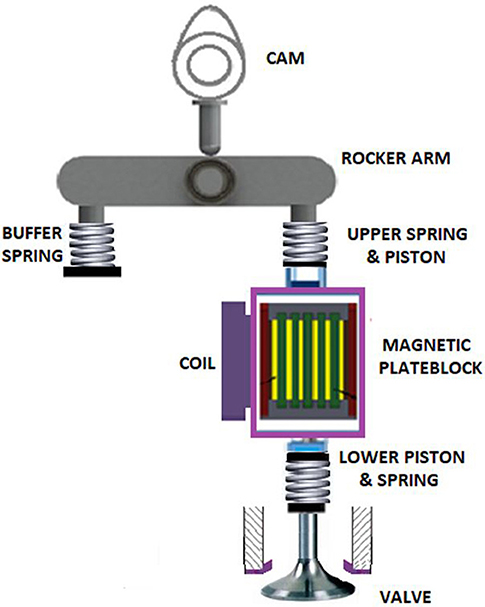
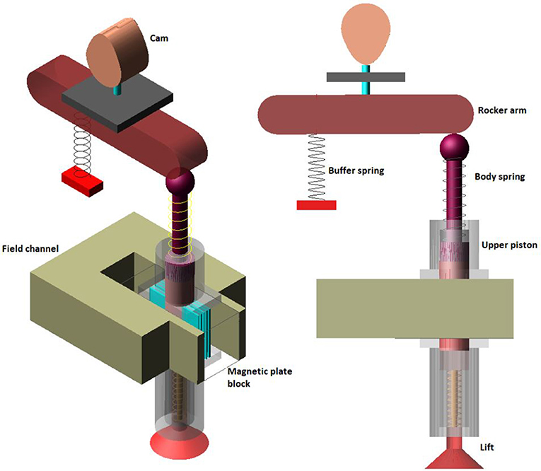
The model of the new magnetorheological fluid variable valve with a spring buffer is displayed in Figure 1. The cam and follower set provide default valve actuation movement to the rocker arm. Then, the rocker arm transfers that motion to the side spring and the upper spring of the body simultaneously. The side spring, also called the buffer spring, compresses due to the rocker's motion. The upper spring is connected to the upper piston, which is connected to the plates in the magnetic plate block. The motion of the upper piston is transferred to the lower piston via these MR plates. The magnetic plate block has a series of MR fluid-filled plates and is surrounded by magnetic coils. The block changes the valve lift and timing by changing the MR fluid's flow resistance force. Finally, the lower piston is connected to the engine intake–exhaust valve with a return spring.
MRF-140CG (LORD Corporation, North Carolina, United States), which is an established and high-grade MR fluid, was used for this model. The properties of this fluid are as follows: the liquid viscosity at 40°C is 0.280 ± 0.070 Pa·s, the density is 3.54–3.74 g/cm3, the solid content by weight percent is 85.44%, the flash point is above 150°C, and the operation temperature is −40°C to 130°C (Lord-corporation, 2012). This fluid has favorable resistance to particle sedimentation; thus, it produces less sediment during short-time idle situations compared with other approaches. Moreover, sediment iron particles can be easily suspended in the MR fluid after only a few running cycles. Therefore, particle sedimentation is not a major problem for this device.
Working Modes
When the magnetic coils are energized, the magnetic field increases the flow resistance force in the MR fluid-filled plates. This force can be changed dynamically using magnetic field intensity control. By harnessing this flexibility, the required valve opening variations can be attained. This new MR fluid variable valve can control the required valve opening modes—fully open, fully closed, and adjustable.
Full Open Mode
When the new MR fluid variable valve is fully open, as shown in Figure 2A, the rocker pushes the upper piston body. Then, this force is transferred to the bottom side by the MR valve system to push the lower piston to open the valve. The upper and lower springs and the side-by-side springs are compressed simultaneously, and the rocker arm has a horizontal downward movement. At this time, the magnetic pole coils do not generate any current, that is, the MR fluid does not have any resistance except its natural viscosity, and the valve opens downwards smoothly.
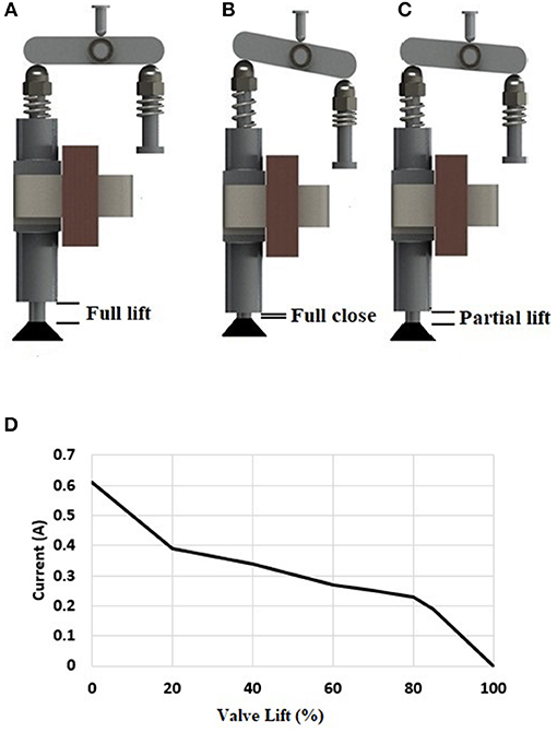
Figure 2. Valve train mechanism at (A) fully open, (B) fully closed, (C) partial conditions, and (D) required current for different lifts.
Fully Closed
In the fully closed mode, as shown in Figure 2B, the coil current reaches its maximum value. Thus, a strong magnetic field is generated, and the resistance reaches its maximum value. When the rocker arm is pushed downward, the resistance of the magnetic pole region prevents the upper piston from being pressed downward. Thus, the valve lift is zero. At this time, the force on the side spring in this mode is larger than the forces in all other modes, and the rocker is in an inclined position.
Partially Open
In this mode, the resistance in the MR fluid can be controlled by varying the current in the coils. Based on this current control, as shown in Figure 2D, the resistance force against the piston motion varies. Thus, the side-by-side springs have different amounts of compression, as shown in Figure 2C. Therefore, the valve opens in proportion to the lift.
Moreover, by changing the timing of the applied current, the valve opening time can be delayed, as shown in Figure 12. When the valve is about to open based on the default cam timing, that is, at ~117°, a maximum current of 0.6 A is applied. When the required timing angle is attained, the current is reduced to zero immediately. Because of the design restriction, this device cannot provide valve closing variations, that is, an early valve closing option. Therefore, the valve closing timing is fixed based on the cam default angle.
Optimization of Magnetic Plate Block
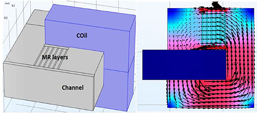
The magnetic plate block is the most important part in this device as it provides the required resistance force. Figure 3 presents the magnetic field flux direction and a top view and 3D diagram of the resistance valve (including the coil). The larger the magnetic field through the MR layers is, the greater is the resistance force generated by this block. By using a high-resistance force, greater spring stiffness can be obtained to achieve higher rotational speeds.
The main objective of this step is to maximize the resistance force in the given geometric constraints. Resistance force in a plate block is a cost function, which depends on the input ampere turn (AT), core material, magnetic channel width (w) and height (L), MR fluid layer thickness (h), partition plate thickness (s), and end wall thickness (d).
A magnetic analysis software program was used to achieve this optimized result. A 3D simulation model of the magnetic plate block was built, as shown in Figure 3. Parameters for optimization and governing equations were also included. After several magnetic simulations were conducted, these dimensions were optimized.
For the resistance force simulation of MR fluid, the MR fluid chaining force is as presented in Equation (1).
where, τy is the shear stress in the MR fluid and depends on the magnetic field (Equation 2).
MR fluid also contains viscous damping force as given in Equation (3).
The total force can be calculated using the formula after the total number of partitions in Equation (4).
Here, B is the magnetic induction, L is the length of the magnetic field channel, h is the gap between the upper and lower plates, Ap is the effective area of the piston, x is the liquid flow rate, and c1 is the parameter value in the range of 2.07–3.07 that is presented in Equation (5).
where, μ is the MR fluid viscosity coefficient and k can be obtained using Equation (6).
This plate block design is not complicated; thus, the straightforward local optimization procedure was used. Because of volume restrictions on the engine and manufacturing aspects, the maximum possible resistance force must be achieved at the smallest plate block. Therefore, the designed parameters have limits, and the optimized results must be below those limits.
For design flexibility, the cross-sectional area of the magnetic channel is considered to be rectangular. The primary parameters of the design of the resistance valve include the thickness of the MR fluid layer and that of the separator. The thickness of the resistance valve affects the number of layers of the MR fluid. The greater the number of layers, the greater is the resistance of the resistance valve. However, the volume of the resistance valve is limited by the volume of the cylinder head. The thinner the MR fluid layer thickness is, the higher is the resistance. If the MR fluid layer is too thin, the MR fluid cannot pass fully through it, causing excessive resistance. Thus, a thickness of 1 mm was applied. The thinner the separator is, the greater is the resistance. However, an extremely thin separator causes the separator to deform when it is subject to force. Therefore, a thickness of 3 mm was applied. Finally, six layers and five partitions were used, as shown in Figures 4A,C.
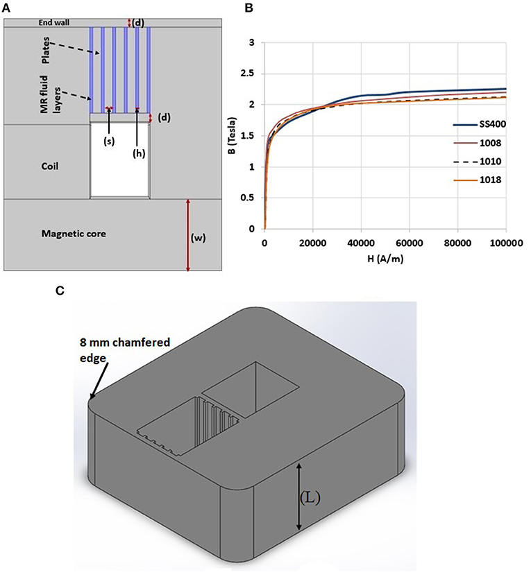
Figure 4. (A) Schematic diagram of the thickness of the magneto-rheological fluid layer and the thickness of the separator (B) comparison of B-H curves of magnetic materials (C) 3D view of magnetic plate block.
Fixed parameters:
• Structure of core = rectangular;
• MR fluid layer thickness (h) = 1mm;
• Plates thickness (s) = 3mm.
Variables for the optimization
• Material selection,
• End wall thickness (d),
• Magnetic channel width (w) and height (L),
• Input current.
Due to the characteristics of the MR fluid, a material with high magnetic permeability must be used for the resistance valve body. The magnetic induction intensity B in different materials is different under different magnetic field strengths H. A comparison of the B–H magnetic induction curves of different materials revealed that pure iron has a high permeability of almost 100% but is difficult to manufacture. Steel 1008 is iron with 0.08% carbon content, steel 1010 is iron with 0.1% carbon content, and steel 1018 is iron with 0.18% carbon content. After a discussion was held on materials with processing plant personnel, SS400, which is a low carbon steel with a carbon content of 0.15–0.2%, was considered the most suitable material; its B–H curve is displayed in Figure 4B. B–H curve details can be obtained from the studies conducted by Lee et al. (2013) and Shiao and Dat (2013).
Figure 4B reveals that when the magnetic field strength is below 30 kA/m, steel 1008 has the highest magnetic flux density. Nevertheless, when H is in the range of >30 to 100 kA/m, SS400 superior better properties, as presented in its curve. The magnetic flux density of SS400 generated at a lower magnetic field strength increases slowly, which implies that resistance control is easier. Moreover, the maximum resistance of SS400 is better than that of other low carbon steels. Therefore, SS400 was selected as the material for the block and plates of the resistance valve body.
To prevent leakage of the MR fluid, the resistance valve wall plate was designed to block the MR fluid on both sides of the resistance valve. The thickness of the wall plate not only affects the strength of the resistance valve but also the maximum resistance of the valve. If the wall is thin, it can easily be magnetically saturated. Thus, most of the magnetic flux is forced to penetrate the MR fluid and plates. Thus, the magnetic field in the MR fluid is sufficiently strong to produce a high-resistance force. By contrast, if the wall is too thick, most of the magnetic flux penetrates the wall and does not penetrate the MR fluid and plates. Thus, the applied magnetic field in the MR fluid is weak, and thus, the produced resistance force is weak. The relationship between wall thickness and resistance at a coil input of 2000 AT is presented in Figure 5A.
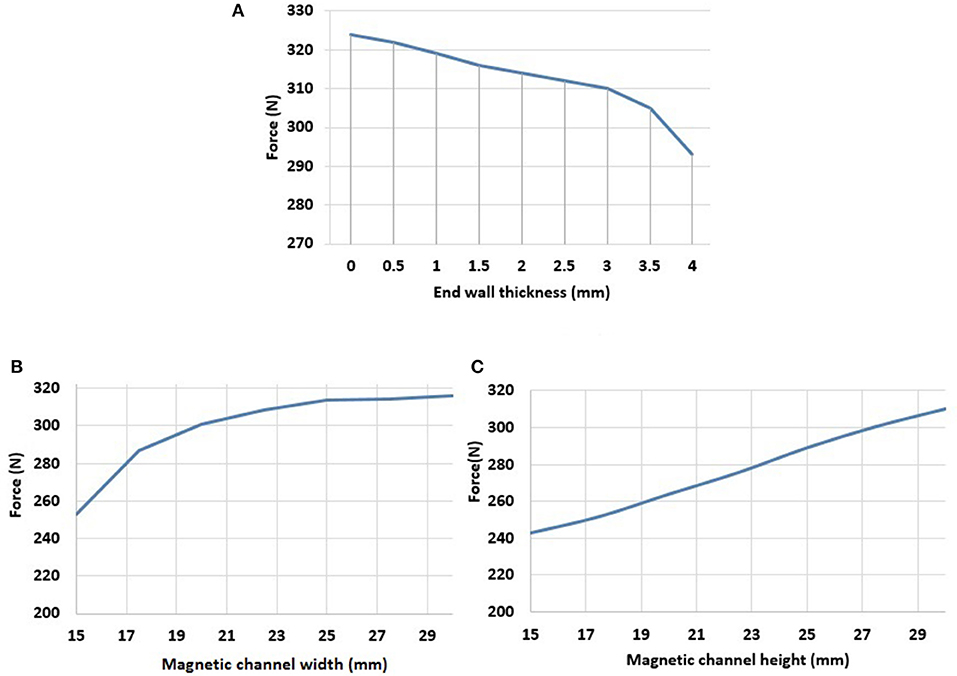
Figure 5. (A) Maximum resistance force with different wall thicknesses (B) maximum resistance at different magnetic channel widths (C) maximum resistance at different magnetic channel height.
Figure 5A proves that the thicker the wall plate is, the lower is the resistance force. As aforementioned, this is because a large wall allows more magnetic flux to pass through and causes less magnetic flux to pass through the MR fluid. Thus, less resistance force is produced. The appropriate thickness of this device was found to be 3 mm. As presented in the figure, the resistance force at a wall thickness of 3 mm was only 9 N lower than that at a thickness of 1 mm (resistance at 3 mm is 97% of that at 1 mm). The resistance force was significantly reduced by 17 N when the wall thickness changed from 3 to 4 mm (resistance at 4 mm is 94.5% of that at 3 mm). Therefore, it is appropriate to select a thickness of 3 mm to obtain sufficient structural support and reduce the loss of resistance force.
Figure 5B presents an analysis of the width of the magnetic flux channel with respect to the resistance force. In the analysis, width values from 15 to 30 mm were studied and maximum resistance change was observed.
The magnetic channel cross-section area affects magnetic flux. The larger the cross-sectional area of the magnetic channel is, the higher is the magnetic flux. However, because the total volume was limited by the engine cylinder head, the area was set to 900 mm2. As shown in Figure 5B, the smaller the width of the magnetic channel is, the smaller is the resistance force. However, the maximum resistance force was saturated when the magnetic path width was higher than 25 mm. This saturation occurred because the width of 25 mm was sufficiently large to allow most of the magnetic flux to pass through. Thus, the resistance force increased by only 2.269 N (about 0.72%) when the thickness value increased from 25 to 30 mm. For material mitigation, a thickness of 25 mm is the most suitable. As shown in Figure 5C the relation between resistance force and channel height is linearly proportional. Therefore maximum allowable height is considered for this design.
Next is the selection of end wall for the prevention of MR fluid leakage. At the beginning of valve design, two options for the end wall were considered: non-magnetic material end wall and magnetic end wall. There are advantages and disadvantages for both designs. Non-magnetic end wall gives larger MR resistance force (because of more magnetic field in MR layers as shown in Figure 6B, but it increases valve volume because of the anti-leakage mechanisms, like O-ring etc. It also increases the manufacturing complexity that is not good for mass production conditions. On the other hand, if magnetic material is used for end wall, the MR resistance force is reduced, but the valve has simple structure. Therefore, the end wall was designed as thin as possible to get magnetic saturation in the path of end wall on purpose. Because of the magnetic saturation at the end wall, magnetic flux going through this short path is limited, and then most of magnetic flux will flow to the MRF layers. That is why the magnetic flux density in end wall at (Figures 3, 6A) are so high, and this is the expected effect in design.
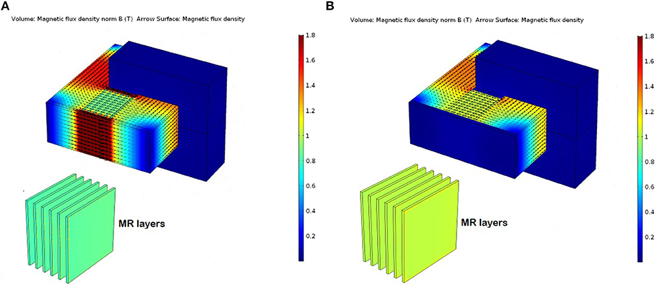
Figure 6. Magnetic simulation results of the (A) final design (B) design with non-magnetic end wall.
Computer simulations of these two optional designs were performed. According to those simulation results, the resistance force of the design with magnetic-material end wall is 303 N, whereas the force of the design of non-magnetic (aluminum) end wall produces 365 N. Thus only 16% force reduction in the magnetic end wall case. It proves that the magnetic-end-wall design can obtain simple system mechanisms without much performance reduction. It is a compromise between the force performance and mass-production manufacturing cost. Finally, it was decided that little force performance was sacrificed to get benefits of manufacturing simplicity and cost. Therefore, single component structure (magnetic end wall) was considered for the MR valve as shown in Figure 4C.
The magnetic induction for this final design is presented in Figure 6A. The magnetic induction intensity using the final parameters was almost saturated in the magnetic channel, which implies that the parameters were close to the limit of lightweight materials.
The AT number has a considerable influence on the resistance force of the plate block. A high AT number can result in a strong magnetic field and thus a large resistance force. However, the magnetic induction intensity can increase only when the magnetic channel is not saturated. The maximum electrical current provided by the power supply in this study was 2 A. A large resistance force can be generated in the plate block if the number of coil turns increases. The maximum force can be reached when the magnetic flux channel is magnetically saturated.
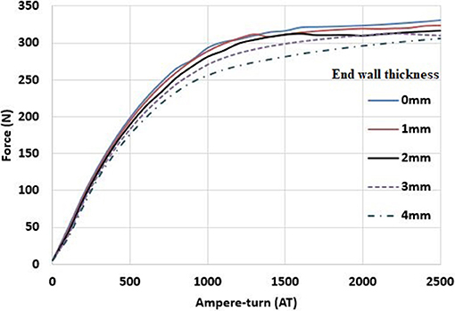
After applying a current of 2 A, 4361 AT can be achieved. However, because of the difficulty in winding, the number of windings is reduced. Finally, the total available number of ATs was 2500 AT in simulation, and only 1500 AT was used in practical applications. Moreover, the thickness of the end wall is also mentioned together, as shown in Figure 7. The maximum resistance force in the plate block can be observed under various conditions.
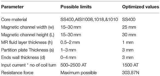
Figure 7 shows that the force increase rate begins to slow down at ~1200 AT. When the ATs are ~1500 AT, the force still increases as the electric current increases, but the force is almost saturated. Moreover, the difference in force value for an end wall thickness of 3 mm and 1 mm is only 10 N. Even for a thickness of 3 mm from 1500 to 2000 AT, only an increase of 10 N was observed. Considering the difficulty and manufacturing processes involved in winding technology, an end wall thickness of ~3 mm should be reserved to successfully achieve the coil winding. The final AT setting was 1500 AT, and a wall thickness of 3 mm was the most suitable. From these magnetic simulations, the design of magnetic plate block was optimized. Moreover, the different resistance forces were calculated for the various valve actuation conditions. Table 1 presents the final parameters and maximum resistance. The final step in size reduction is cutting out the corners by 8 mm as shown in Figure 4C, which has a negligible negative effect on magnetic intensity.
Dynamic Simulations
Several mechanical and electrical valve trains have been used in present engines, which have limited sets of valve profiles. The proposed valve train is more flexible and was designed to enable more variations in valve opening. Therefore, the purpose of this simulation is to identify whether the proposed valve train can achieve more opening variations.
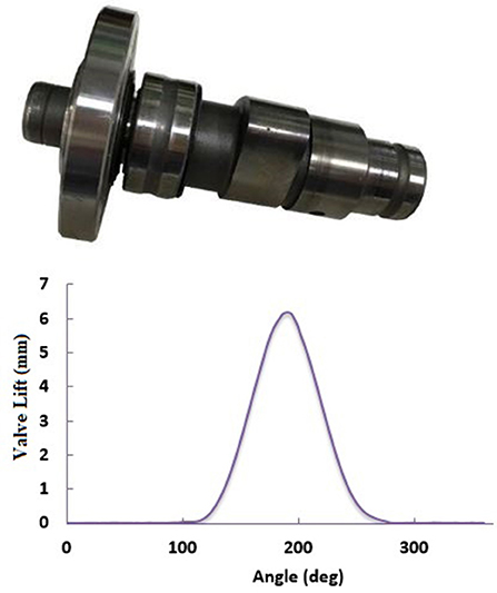
To understand the working operational characteristics of the valve, an MR valve model was developed in the Adams simulation software program. The input of the model is the plate block's resistance force that is generated from magnetic simulations, and the cam speed is 30 rpm. Because of the limited equipment available in the laboratory, the experimental cam of a 125-cc single-cylinder engine was used, as shown in Figure 8.
The resistance force of the magnetic plate block was obtained from the magnetic field simulation program. Based on that resistance, the elastic coefficient of the buffer spring and the upper and lower springs of the body were obtained. After all power parameters and size settings were completed, the kinematic model of the MR valve was achieved, as presented in Figure 9.
Cam Analysis
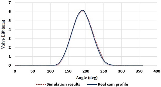
After the kinematic models were developed, the dynamic performance of the valve was simulated. The cam was the active component in this study that pushes the entire valve. Therefore, the cam had considerable importance. Figure 10 presents a comparison between the modeled cam profile of the simulation and the contour of the real cam. The results reveal that the simulated cam profile is markedly similar to the contour of the real cam. Because of the friction of the mechanical components and errors due to the spring stiffness, only minimal difference were observed in valve closing time. Thus, this cam model can be used as the primary active component in the valve train model for conducting dynamic analysis to operate the valve.
Dynamic Lift Simulation
The purpose of this simulation was to study the different lift options of the proposed valve train. By changing the magnitude of resistance force in the magnetic plate block (which acts as a reverse acting force to the piston motion), the respective lifts can be achieved. For example, a 0-N resistance force is required to activate full lift mode, a 25-N resistance force is required to lift the valve by 85%, and a 45-N force is required to lift the valve by 75%. Lifts of 0, 20, 40, 60, 80, and 100% were tested.
When the valve was fully closed, the resistance force of the magnetic plate block was at its maximum, that is, at approximately 270 N, as shown in Figure 11A. Therefore, the valve does not open, and the entire compression force is on the buffer spring. This force compresses the buffer spring to its maximum lift. The displacement of the buffer spring for different lift values is displayed in Figure 11B. Similarly, during the partial valve lift conditions, part of the compression force of the rocker arm is transferred to the buffer spring.
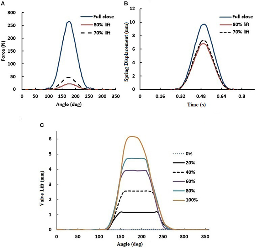
Figure 11. Computer simulation results of (A) resistance force at different lifts, (B) compression of buffer spring lift at different lifts, and (C) different valve lifts.
From the dynamic simulation results of the variable lift of this model, as shown in Figure 11C, it is clear that the new MR valve has a favorable effect on the variable lifts. Within the allowable compression amount of the buffer spring and by regulating various types of compression, the function of various valve lifts can be attained.
Dynamic Valve Timing Simulation
Next, the possibilities of VVTs were analyzed. To understand the default timing, 25° delay, 50° delay, and 75° delay conditions were simulated. Figure 12A presents a schematic of the force applied during the simulation. When the valve was about to open, that is, at approximately 117°, a maximum force of 270 N was applied. When the required timing angle was attained, the force was reduced to zero immediately.
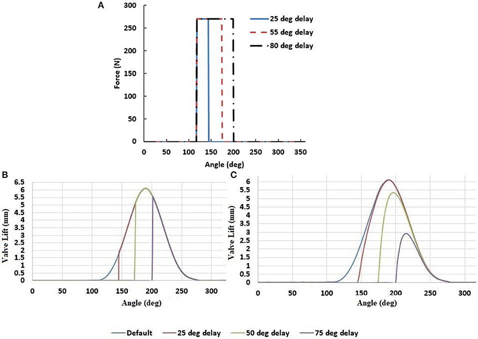
Figure 12. (A) Schematic diagram of simulated force application (B) variable timing expected profiles (C) dynamic simulation of variable timing of the valve with full lift.
Figure 12C shows the dynamic simulation of the various timings of the valve in the full lift condition. Although the cam began to push the rocker at its default timing, that is, at 117°, the valve did not open until the set time was reached because of the resistance force, as shown in Figure 12A.
As shown in Figure 12B, after the required time was reached, the expected valve profile for a full lift could be observed. However, this behavior cannot be attained in a real-world scenario because of magnetic hysteresis. The resistance force in the magnetic plate block was gradually reduced to zero. By that time, the cam profile began a downward trend, as shown in Figure 12C. Thus, the obtained profile was slightly different from the expected profile. However, these profiles are useful for enhancing the engine performance. In the future, by performing engine simulation studies, optimal profiles can be determined for given speed and load conditions.
Dynamic Valve Lift and Timing Simulation Results
Finally, the proposed valve train was tested in terms of obtaining various valve lifts and timing flexibility simultaneously. Figure 13 presents the simulation results of the variable timings of the valve at an 85% lift. Because of the resistance force throughout the valve lifts, as shown in Figure 11A, a maximum lift of only 85% was attained for all the timing conditions. As such, both VVT and VVLs were achieved simultaneously. Similarly, Figure 14 displays the simulation results of various timings of the valve at a 70% lift. The new MR valve controls both various lifts and various valve opening times.
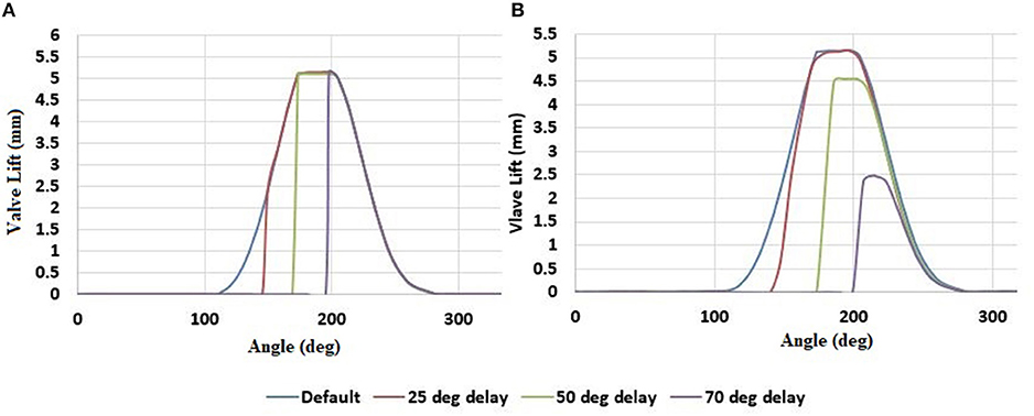
Figure 13. Different timings with 85% valve lift (A) expected profiles (B) MR valve-train simulation results.
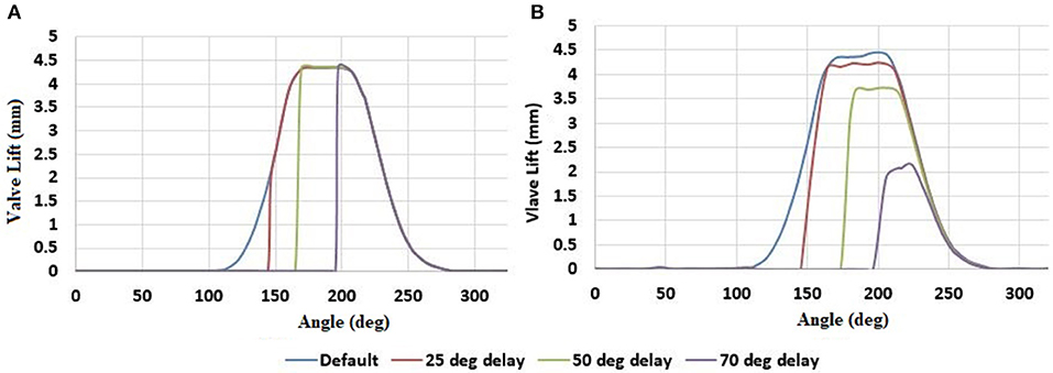
Figure 14. Different timings with 70% valve lift (A) expected profiles (B) MR valve-train simulation results.
Figure 12B shows the dynamic simulation of the variable timing of the valve in the full lift condition. Although the cam began pushing the rocker at its default timing, that is, at 117°, the valve did not start opening until the set timing−120°, 145°, 175°, and 200°–is reached because of the resistance force that is shown in Figure 12A. The maximum lifts were attained as each cam lifts were available at that angle.
However, at lower lift modes, some lift fluctuations were evident when the time for the maximum lift was reached because of a high degree of tension in the springs. Moreover, during late opening times, the valve profiles could not reach the highest point of the expected profiles. As discussed, this is due to magnetic hysteresis. This valve train was developed to attain variable profiles and not to achieve particular profiles. All the aforementioned simulations reveal that the proposed valve train can provide valve profiles, that is, VVT, VVL, and VVT&L. Therefore, the proposed MR valve train is valid and useful.
The introduced device is a novel IC engine valve train. Therefore, this paper discusses the conceptual model and valve working validation only. In the future, an experimental study will be conducted on the prototype to elucidate its operational modes at different speeds. Magnetic hysteresis is one of the major problems in such components that affects the valve response. However, in the proposed device, magnetic hysteresis can be avoided by using a control strategy—input current timing. After experimental study is conducted, this control strategy can be established. Moreover, considering manufacturing aspects end wall of magnetic plate block was designed with magnetic material, which has little performance reduction. In the future, this device will try to use non-magnetic end walls to enhance the force performance of the MR valve while balancing its manufacturing cost, design complexity, and device weight. Thus, this device will be more attractive to the users especially in long run.
Conclusions
This study introduced a novel MR valve train that is lightweight and consumes less energy than other related devices. Because of the volume restrictions on the engine, the maximum possible resistance force from the plate block should be achieved at the smallest plate block. This task was achieved by using an optimized design for a magnetic plate block and was explained using magnetic simulation. The possibilities of valve actuation with different opening variations and the force distribution from the cam to the magnetic plate block, to the springs, and the valve were simulated. Based on those simulations, the designed MR valve train was proven to be flexible in producing various valve profiles with different valve times and lift combinations. Therefore, this valve, with an appropriate valve opening strategy, could be used in an IC engine to improve the engine's efficiency and reduce exhaust gas emissions.
Author Contributions
Idea, conceptual study, theory, literature study, and manuscript quality enhancement done by YS. Magnetic and dynamic simulation, manuscript writing done by MK. Structural design and modeling work done by J-WJ.
Conflict of Interest Statement
The authors declare that the research was conducted in the absence of any commercial or financial relationships that could be construed as a potential conflict of interest.
Acknowledgments
This research is financially supported by Ministry of Science and Technology, Taiwan (project number: MOST 105-2221-E-027-091).
References
Bernard, L., Ferrari, A., Micelli, D., Perpttp, A., Rinolfi, R., and Vattaneo, F. (2009). Electro-hydraulic valve control with multiair technology. MTZ Worldwide 70, 4–10. doi: 10.1007/BF03226988
Dyke, S. J., Spencer, B. F., Sain, M. K., and Carlson, J. D. (1996a). Modeling and control of magneto-rheological dampers for seismic response reduction. Smart Mater. Struct. 5, 565–575. doi: 10.1088/0964-1726/5/5/006
Dyke, S. J., Spencer, B. F., Sain, M. K., and Carlson, J. D. (1996b). Phenomenological model of a magneto-rheological damper. J. Eng. Mech-ASCE. 123, 230–238.
Dyke, S. J., Spencer, B. F., Sain, M. K., and Carlson, J. D. (1998). An experimental study of MR damper for seismic protection. Smart Mater. Struct. 7, 693–703.
Flierl, R., and Klüting, M. (2000). The third generation of valvetrains-new fully variable valvetrains for throttle-free load control. SAE Technical Paper (Detroit, MI), 0148–7191.
Ichwan, B., Mazlan, S. A., Imaduddin, F., Koga, T., and Idris, M. H. (2016). Development of a modular MR valve using meandering flow path structure. Smart Mater. Struct. 25:037001. doi: 10.1088/0964-1726/25/3/037001
Lee, H. B., Kwon, H., and Min, K. (2007). Effects of various VVA systems on the engine fuel economy and optimization of a CVVT-VVL SI engine using 1D simulation. Int. J. Automot. Technol. 8, 675–685.
Lee, J. H., Han, C., Ahn, D., Lee, J. K., Park, S. H., and Park, S. (2013). Design and performance evaluation of a rotary magneto-rheological damper for unmanned vehicle suspension systems. Sci. World J. 2013:894016. doi: 10.1155/2013/894016
Lord-corporation (2012). Magneto-Rheological Fluid MRF-140CG. Available online at: http://www.lordfulfillment.com/upload/DS7012.pdf
Phu, D. X., and Choi, S. B. (2019). Magnetorheological fluid based devices reported in 2013–2018: mini-review and comment on structural configurations. Front. Mater. 6:19. doi: 10.3389/fmats.2019.00019
Pierik, R. J., and Burkhard, J. F. (2000). Design and development of a mechanical variable valve actuation system. SAE Technical Paper (Detroit, MI), 0148–7191.
Sawant, P., and Bari, S. (2018). Effects of variable intake valve timings and valve lift on the performance and fuel efficiency of an internal combustion engine. SAE Technical Paper, 2018-01-0376. doi: 10.4271/2018-01-0376
Shiao, Y., and Cheng, W. H. (2016). Performance investigation of an SI engine with VVT and VVL based on magneto-rheological valve. T. Can. Soc. Mech. Eng. 40, 749–760. doi: 10.1139/tcsme-2016-0061
Shiao, Y., and Dat, L. V. (2013). A new electromagnetic valve train with PM/EM actuator in SI engines. T. Can. Soc. Mech. Eng. 37, 787–796. doi: 10.1139/tcsme-2013-0066
Smith, C. (2018). Electro-Mechanical Hydraulic Valve Lifter for Precise Control of Fuel Consumption. US. Patent No. US20180187577A1. Washington, DC: U.S. Patent and Trademark Office.
Sun, Z., and He, X. (2007). Development and control of electro-hydraulic fully flexible valve actuation system for diesel combustion research. SAE Technical Paper (Rosemont, IL), 0148−7191.
Yao, Z., Yap, G., Fook, F., and Chen, G. (2002). MR Damper and its application for semi-active control of vehicle suspension system. Mechatronics 12, 963–973. doi: 10.1016/S0957-4158(01)00032-0
Keywords: magneto-rheological fluid, variable valve timing (VVT), variable valve lift (VVL), engine performance, valve actuation
Citation: Shiao Y, Kantipudi MB and Jiang J-W (2019) Novel Spring-Buffered Variable Valve Train for an Engine Using Magneto-Rheological Fluid Technology. Front. Mater. 6:95. doi: 10.3389/fmats.2019.00095
Received: 30 November 2018; Accepted: 15 April 2019;
Published: 01 May 2019.
Edited by:
Seung-Bok Choi, Inha University, South KoreaReviewed by:
Miao Yu, Chongqing University, ChinaJung Woo Sohn, Kumoh National Institute of Technology, South Korea
Luwei Zhou, Fudan University, China
Copyright © 2019 Shiao, Kantipudi and Jiang. This is an open-access article distributed under the terms of the Creative Commons Attribution License (CC BY). The use, distribution or reproduction in other forums is permitted, provided the original author(s) and the copyright owner(s) are credited and that the original publication in this journal is cited, in accordance with accepted academic practice. No use, distribution or reproduction is permitted which does not comply with these terms.
*Correspondence: Yaojung Shiao, eXNoaWFvQG50dXQuZWR1LnR3
 Yaojung Shiao
 Mahendra Babu Kantipudi
 Jing-Wen Jiang