 Shiwei Chen
 Rui Li2*
 Pengfei Du
 Dingyu Li
- 1Chongqing University of Science and Technology, Academe of Mathematics and Physics, Chongqing, China
- 2Department of Automation, Chongqing University of Posts and Telecommunications, Chongqing, China
This work mainly addresses the establishment of a phenomenological mechanical model for magnetorheological (MR) engine mounts under frequency variation and magnetic variation effects. First, the mounts' reaction force is divided into three parts: a Coulomb damping force, an elastic reaction force, and a viscous damping force. Then, by using correlation analysis on these forces with the frequency and magnetic field, a modified polynomial Bingham parameterized model is proposed. This model takes external current and external loading frequency as the variables. As a result of analyzing the relationship between energy dissipation and storage caused by the external displacement excitation, an identifying method is proposed to identify the nine parameters in the model. Based on this model, an experimental scheme was designed, and the force–displacement relationship of a typical MR mount under different working conditions was tested through an experiment. By using the proposed method, the relationship of the reaction force of an MR mount with current and external loading frequency was obtained. The experimental results show that the proposed model can correctly reflect the wide-frequency dynamic characteristics of the mounts in dynamic stiffness, lagging angle, and hysteretic curve.
Introduction
Engine mounts are usually installed between the engine and vehicle frame. They are used for isolating the engine's vibration, which would spread to the vehicle body, and reducing the vibration amplitude of the engine itself (Shangguan, 2009; Tikani et al., 2015). An ideal engine mount should exhibit a low damping property when the engine is at high revolution speed, and it should be quickly changed to a high damping state when the engine revolution speed is low(Barber and Carlson, 2010). As a new member of the novel smart mount, magnetorheological (MR) fluid mounts boast a series of advantages, such as controllable damping force, simple structure, quick response, low energy consumption, and low cost. Hence, these advantages provide broad application prospects and important research significance for motor vibrating control (Behrooz et al., 2011; Wang and Chen, 2017).
On account of the complex internal structure of MR mounts, the rubber structure features a hyper-visco-elastic-plastic mechanical property. Its elastic modulus has a strong correlation to amplitude (Delattre et al., 2016) and external loading frequency (Lin and Lee, 1998). However, MR fluid, as a non-Newtonian liquid, has the mechanical property that its yield stress varies with the change of external applied magnetic field, and it has the frequency correlation that its apparent viscosity mainly varies with the external loading frequency (Wang and Faramarz, 2009; Zhu et al., 2011). These characteristics endow the mechanical feature of MR fluid with strong non-linearity (Sado, 2013). Therefore, how to establish the mechanical model accurately and succinctly is continually attracting research in the engineering field (Hoang et al., 2011). The existing studies mainly describe the dynamic characteristics of mounts' components using the following three methods.
First, the lumped parameter method generally adopts bond group theory to describe the relationship of the system's dynamic stiffness and lagging angle with the internal structural parameters of mounts (Farjoud et al., 2014; Tikani et al., 2015). Because the lumped parameter method is based on a linear viscoelastic system, there is great difference between the calculation model and the final testing results.
Second, the finite-element method (FEM) involves the simulation of dynamic characteristics of mounts through the secondary development of commercial finite-element software (Shangguan and Lu, 2003; Wang and Lu, 2003). Nguyen (Nguyen et al., 2013) investigated the optimal design of an engine mount based on the FEM. However, because of the fluid–solid coupling characteristics of MR mounts and the fact that numerous experiments (Li et al., 2013) are required to obtain the parameters of the viscoelasticity, elastoplasticity, and superelasticity of structural materials, it is difficult to predict the reaction force of MR mounts.
Third, the phenomenological model describes the mechanical property of mounts by establishing a presupposed skeleton model and combining experiments with matching the undetermined parameters, which sometimes has no physical meaning, in the skeleton model. Because of the advantages of the simple model and high accuracy, using the Bingham model, Bouc–Wen model, and other improved models based on Bouc–Wen, researchers have applied the phenomenological model method to describe the dynamic characteristics of an MR damper (Razman et al., 2014). For example, Spaggiari and Dragoni (2012) used an improved Bouc–Wen model to perform parameterized modeling for an MR damper at the low-frequency stages. Liao (Chang-rong et al., 2013) conducted magnetic circuit analysis for MR fluid mounts of engines and carried out mechanical-characteristic research on the extrusion model of MR fluid. Finally, that work reveals the relationship between the applied current and extrusion force. Choi et al. (2001) performed fitting calculation on the experimental results of MR fluid mounts through a polynomial model. This model boasts the advantages of high control accuracy and quick reverse current of the reacting force.
Recently, research on applying MR dampers for vibration control of mechanical system has made great progress. Many models that possess the merits of high accuracy in the prediction of MR dampers with low-frequency behavior have been widely investigated. For examples, Xu et al. (2014) utilized the Bouc–Wen model to model a vehicle MR suspension, and Bai et al. (2015) studied a new MR damper with an inner bypass configuration.
There already have been many studies for system modeling with the characteristics of hysteresis (Swevers et al., 2000). However, unlike the vehicle suspension system, the engine isolation system has its unique properties. It operates under a lower vibration amplitude and a broad band of frequency (0–100 Hz). Moreover, the vibration of the engine system is mainly caused by the engine's unbalance force. Hence, the vibration source frequency is deeply related to the engine revolution speed, which could be tested easily. Although Chen et al. (2016) proposed a new model to describe mechanical behaviors of MR dampers working at the medium-frequency range, current studies have not considered the modeling of MR dampers for a broadband dynamic range. Therefore, a control method based on existing models would be ineffective or even counterproductive when the engine is vibrating at high frequency. In addition, because the excitation frequency of the engine vibration system varies in a wide range, the MR fluid and rubber in the MR mount face the displacement excitations with a great difference in rate. Therefore, this creates higher requirements for broadband mechanical properties characterization of MR mounts.
To address the above-mentioned problem, by considering the broadband characteristics of an engine vibration system and ignoring the amplitude effect on the mechanical behaviors of the MR mounts, this study takes an MR mount as the example, proposes a polynomial Bingham phenomenological model through the component analysis of the mounts' reaction force, and comes up with a parameter-identifying method for the polynomial model by analyzing the energy dissipation and storing relationship of external excitation. Through testing experiments, the relationship that the reaction force of MR mounts varies with the current and excitation frequency was obtained. The comparison results show that this improved model can correctly reflect the dynamic characteristics of wideband MR mounts.
Phenomenological Mechanical Model
The present work adopts MR fluid mounts as the study object, as shown in Figure 1. The piston rod of the MR fluid mounts uses a rigid connection with a vibration separating system. The vibration excited by the vibrating source causes an up–down movement of the piston rod so as to drive the up–down movement of the extrusion disc. Then, the MR fluid of the working cylinder spreads toward the two sides under the extrusion of the disc, forming a flow. A magnetic field is produced from the magnetic exciting coil, vertical to the extrusion disc. The flowing direction of the MR fluid is parallel to the extrusion disc; thus, the flowing direction of the MR fluid is vertical to the magnetic field, obstructing the flow. By this means, the damping force can be changed.
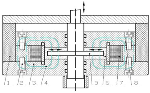
Figure 1. Structural diagram of MR mounts based on extrusion working mode (1)Rubber gasket (2) Connecting bolt (3)Connecting base (4) Exciting flux (5) Extrusion round disc (6) MR fluid (7) Magnet exciting coil (8) Seal covered plate.
Furthermore, Figure 2 gives the structure parameter of the MR mounts work area, and the parameter value is given in Table 1.
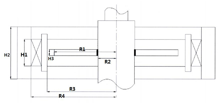
Figure 2. Structure parameters diagram of the MR mounts.
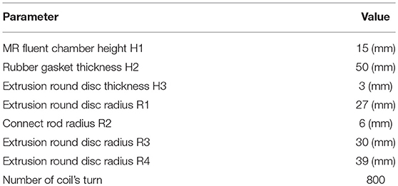
Table 1. Structure parameters value of the MR mounts.
To show that the working area of the MR mount is in the path of the magnetic circuit, Figure 3 gives the magnetic circuit of the MR damper analyzed by the FEM software COMSOL 5.0. As Figure 3 shows, the magnetic field in the working area is close to 0.8 T when the coil current is 1 A.
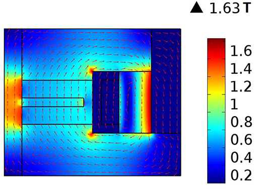
Figure 3. Result of the magnetic circuit analysis.
According to the traditional Bingham model, as shown in Figure 4, when the engine vibrates, the extrusion disc moves a displacement X, and the reaction force to the engine (Hong et al., 2008) from mounts can be expressed as:
According to the traditional Bingham model, the reaction force of MR mounts can be divided into three parts. The first part F1 represents the viscous damping force produced from the rubber gasket and MR fluid, and that can be regarded as the function of the displacements-velocity in the Bingham model.
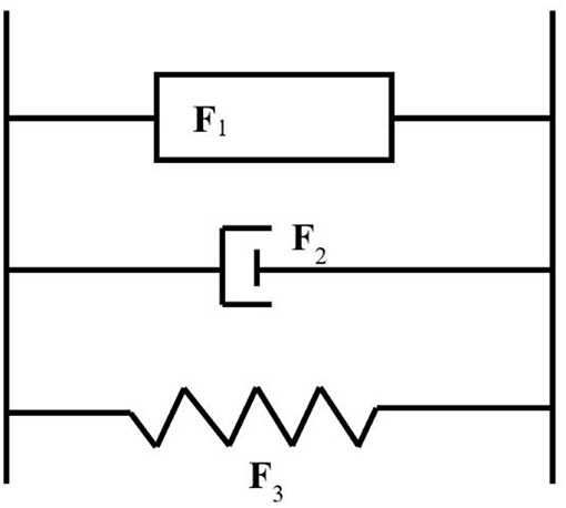
Figure 4. The Bingham phenomenological model.
The second part of the reaction force F2 is the Coulomb damping force produced by the magnetic effect of the MR fluid. Yield stress is mainly controlled by the magnetic-field strength. Therefore, F2 is related to the current applied to the mounts. It is a kind of adjustable damping force, with the damping force characteristics of a friction damper.
The elastic force F3 represents the equivalent stiffness of the rubber gasket mounted on the external package. It changes with the frequency because of the viscoelasticity of rubber as a polymer material.
Because of the small amplitude of engine vibration, it can be simplified as follows. According to the correlation analysis above, the reaction force expression equation is built by a binomial fitting according to current I and external-loading frequency ω to obtain the improved Bingham model.
Where c(ω) is the equivalent viscous damping of the MR mounts; k(ω) represents the equivalent stiffness of the MR mounts; FI is the coefficient of Coulomb damping of the MR mounts; and the parameters AI, BI, CI, Ak, Bk, Ck, Ac, Bc, and Ccare the fitting parameters used to describe the dynamic mechanical properties of MR mounts.
Parameter Identification
If the mounts are subjected to a forced vibration under a single-frequency sinusoidal vertical displacement excitation with the amplitude of X0, the mounts' movement can be expressed as follows.
Within a complete period, according to Equation (3), the external work Popmade by the displacement exciter to mounts can be expressed as:
According to energy equivalence, within a complete period, the external work equals the energy internally consumed within the mounts.
where PI represents Coulomb damping force work and Pcrepresents damping force work.
The physical significance of Equation (5) demonstrates that the work done by the displacement exciter within a complete period is consumed by mounts. The consumed work can be expressed in two parts: one is the energy related to the externally added current intensityPI; and the other is the energy Pc related to the externally applied load.
According to this characteristic, if keeping the amplitude of displacement excitation X0 and the externally applied current I invariable, by measuring the external work under different excitation frequencies and subtracting the test data, the difference between two external works can be derived as
where ωk is the external frequency in the k-th time testing. Concerning Equations (2) and (5), this equation can be derived as follows:
By testing the reacting force of the MR mounts in ωk, ωk+1, and ωk+2, three different excitation frequencies, the expression of the fitting parameters of viscous damping Ac, Bc, and Cc can be obtained as follows.
From Equation (8), it can be shown that the relationship that the equivalent viscous damping of MR mounts changes with excitation frequency can be worked out by an inverse solution of external work under different excitation frequencies through the testing system.
Similarly, if the amplitude of displacement excitation and externally applied frequencies are kept invariable, the external work can be measured under different excitation currents and subtracting the test data.
where Ik is the externally applied current load in the k-th time testing; concerning Equation (5a), this equation can be derived as follows when the k-th and k+1-th time tests are finished.
The two fitting parameters of the Coulomb damping coefficient AI and BI can be obtained as follows.
Additionally, the fitting parameter CI can be obtained as follows when the applied current is zero.
Concerning Equations (11, 12), the three fitting parameters of the Coulomb damping coefficient can be obtained as follows.
Equation (13) is the parameter identifying equation of Coulomb damping. The equation shows that, under the circumstance of presupposing the system equivalent viscous damping, the Coulomb damping coefficient FI can be obtained through the external work under different externally applied current conditions.
After identifying the equivalent viscous damping and coulomb damping force coefficient and solving Equation (4), one obtains
The equivalent stiffness kω in the above equation is the function of frequency, which can be identified by least-squares fitting.
Optimizing Ak, Bk, and Ckcan minimize Equation (15). The optimized solution is the fitting parameter that MR damper stiffness varies with the frequency.
Experimental Testing Procedure
In conclusion, the parameter identification flow of the improved Bingham fitting model proposed is shown in Figure 5 as follows.
(a) Apply a current to the MR mounts; do not change the externally applied load amplitude; measure the displacement–force curve under different external load frequencies; calculate the external work through Equation (4); identify the equivalent viscous damping of the mounts through Equation (6).
(b) Similar to the first step, apply a sine exciting force with the same amplitude and excitation frequency to the MR mounts by different currents to calculate the external work made by different exciting forces; substitute different values of external work into Equation (7) to calculate the Coulomb damping force coefficient of the mount system.
(c) Obtain the inverse solution of the rule that mount stiffness changes with frequency by identifying the obtained viscous damping force and Coulomb damping force.
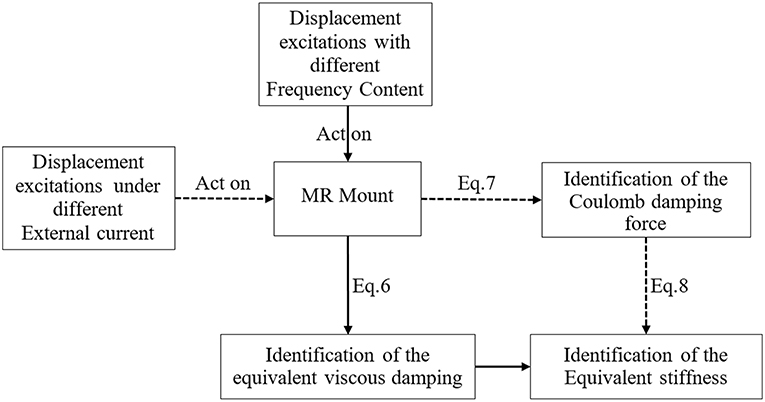
Figure 5. Parameter experimented fitting flow figure to be identified in parameterized model.
Experimental Results and Discussion
The proposed method was applied to MR mounts and an experimental platform, as shown in Figures 6, 7. The MR mounts are installed under the vibration exciting platform composed of the electrohydraulic excitation control system, force sensor, computer, fixture, current source, data collection and control software, and hardware system. The electrohydraulic servo excitation control system includes an MTS 242.01 actuator and a built-in high-accuracy displacement sensor. The force sensor is a BK-1 strain sensor produced by The Aerospace Aerodynamic Research Institute, China.
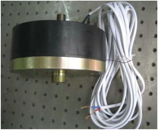
Figure 6. MR mounts adopt in this paper.
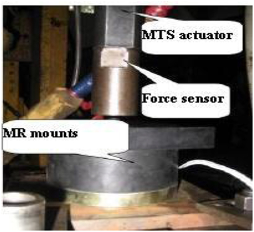
Figure 7. Testing platform of MR mounts.
The main technological parameters of the excitation platform are defined as follows: the maximum vibration excitation amplitude is 5 mm, and the excitation frequency range is 0–150 Hz. In addition, the measurement range of the force sensor is from −6000 to 6000 N, and its accuracy grade is 0.6 N. The measurement range of the displacement sensor is from −10 to 10 mm, and the accuracy grade of the two sensors is 0.005 mm.
Five groups of dynamic characteristic tests under different external loading frequencies were performed on the MR fluid mounts, with the condition not changing the current according to the testing theory. Figure 8 indicates that the mounts' reaction force changes with the time and displacement under the conditions of 600 N preloading force, and Figure 8A shows the reaction force–displacement relationship of the MR mounts in a 0.4 A externally applied current. Figure 8B gives the reaction force–displacement relationship at a 0.5-mm excitation amplitude.
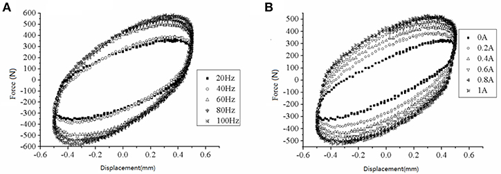
Figure 8. The force-displacement relationship of MR fluid mounts (A) in different excitation frequency (B) in different currents.
According to the theory proposed here, the fitting parameters of dynamic characteristics of MR fluid mounts are calculated, as shown in Table 2.
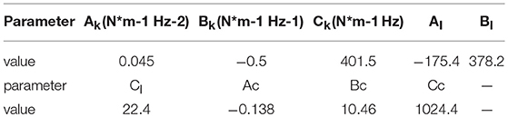
Table 2. Identifying parameter results of MR fluid.
Figures 9–11 illustrate the identification curves, which shows that the dynamic characteristic parameters of MR mounts vary with the current.
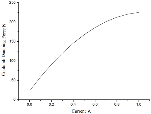
Figure 9. Fitting results of MR mounts coulomb damping force.
The following can be concluded from Figure 9. (a) The Coulomb damping force of the MR mounts increases with the current; when the current exceeds 0.7 A, the Coulomb force rises with the current, but not evidently. This shows that the MR effect of MR fluid tends to a saturation state. (b) When the externally applied current is 0 A, the MR mounts still have some friction damping force of ~22.4 N; when the current reaches 1.0 A, tending to saturation, the largest damping force reaches 225.2 N, and the adjustable multiple is ~10. This demonstrates that the designed MR damper structure can change the damping force within a wide range, with a fine adjustable characteristic of damping force.
It can be concluded from Figure 10 that: (a) the equivalent stiffness of the MR mounts rises with the frequency, and the rising speed goes faster and faster, which is caused by the dynamic effect of rubber, and (b) when the engine is working at a high frequency, the stiffness of the MR mounts is improved up to 821 N/mm—approximately twice 401.5 N/mm, the static value of stiffness. With the rise of the stiffness, the transmissibility of the engine goes faster and faster, which makes it necessary to apply a larger current to improve the Coulomb damping force and achieve vibrating control.
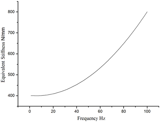
Figure 10. Fitting results of equivalent stiffness of MR mounts.
Figure 11 provides the viscous damping identifying results of the MR mounts. Figure 11 shows that the viscous damping of the MR mounts goes up with the rise of working frequency when the engine is working at a low frequency (lower than 40 Hz), but lowers with the rise of working frequency when the engine is working at a high frequency (higher than 40 Hz), With a view to further verifying the reliability of the fitting results, Figures 12, 13 give the MR mounts' fitting results of dynamic stiffness and lagging angle under different excitation frequencies and external currents. Moreover, Figure 12 provides the fitted and experimental result of the force–displacement relationship.
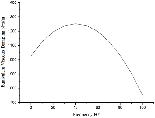
Figure 11. Fitting results of equivalent viscous damping of MR mounts.
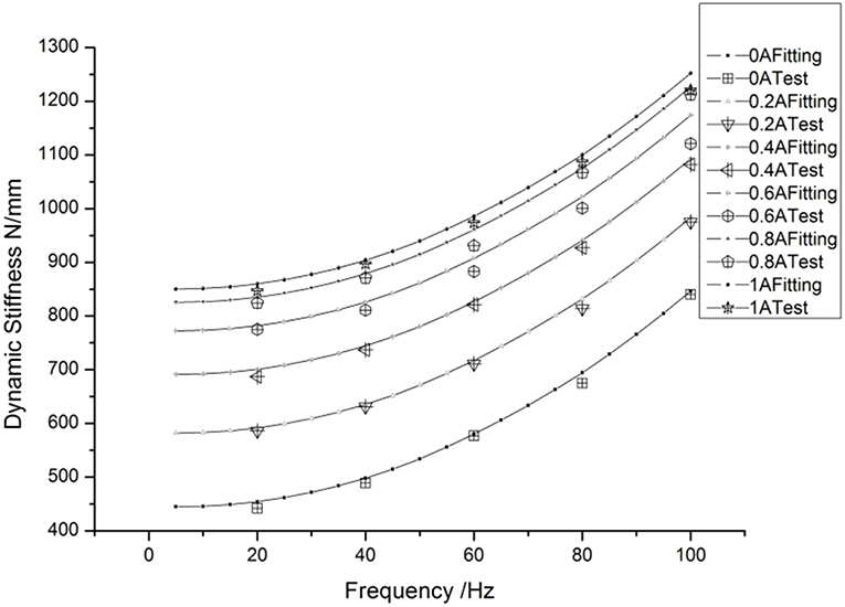
Figure 12. Fitting experiment contrast figure of dynamic stiffness of MR mounts.
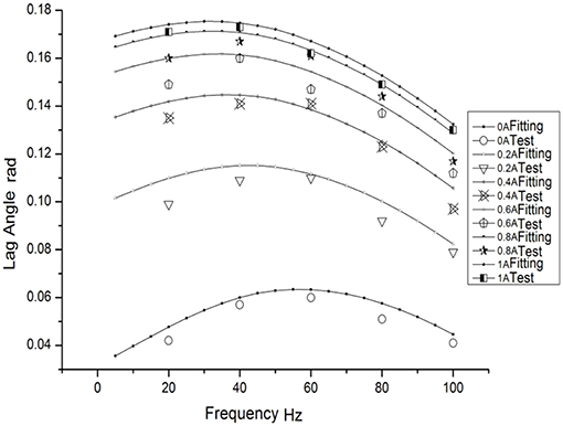
Figure 13. Fitting experiment contrast figure of lagging angle of MR mounts.
By comparing Figures 12, 13, one can find that, because of the inherent defect of the Bingham model at low speeds in describing the mounts' dynamic characteristics, the fitting result has errors at the maximum mount displacement (low-speed range), leading to an obvious difference in the fitting results of dynamic stiffness and lagging angle from the true ones. Figure 14 shows that, in general, the fitted hysteretic curve of the mounts is in accordance with the experimental curve, which demonstrates that the improved polynomial Bingham model proposed can properly describe the dynamic characteristics of the MR fluid mounts in a wide frequency band and lay a rational foundation for the active vibration control and optimal design of engine mounts.
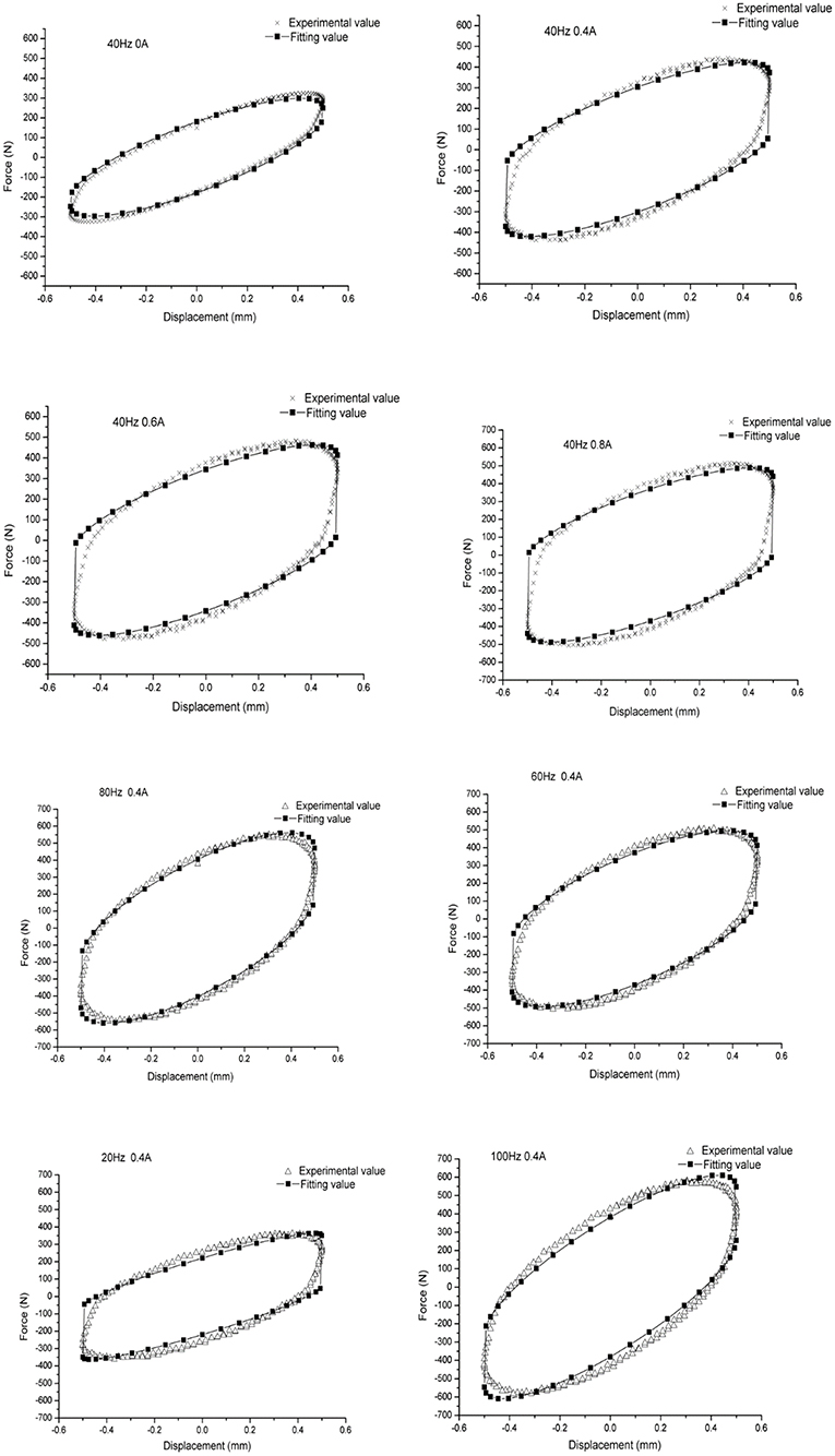
Figure 14. Contrast fitting value figure of the experimental value of hysteretic curve under all working conditions.
Conclusions
For the purpose of describing the dynamic characteristic behavior of MR fluid mounts in a wide frequency band, an improved polynomial Bingham model based on experiments was proposed. The fitted result based on the model shows that the viscous damping of MR mounts goes up with the rise of frequency when working at low frequencies or lowers with the rise of frequency when working at high frequencies. The equivalent stiffness produces a dynamic stiffness effect—that is, the mounts' stiffness rises with the frequency, and the rising speed goes faster and faster, which is caused by the dynamic effect of rubber. It is approximately twice the rubber stiffness in a static status when working at high frequencies. The mounts' Coulomb damping force rises with the increase in current; however, when the current exceeds 0.7 A, the rise is not obvious, which demonstrates that the MR effect tends to a saturation state.
In addition, comparison of the experimental result shows a poor performance in describing the mounts' dynamic effect when the displacement of the mount reaches its maximum. However, the improved polynomial Bingham model can properly describe the dynamic characteristics of the MR mounts in a wide frequency band.
Finally, compared with other parameterized models, this model features simple calculation, fewer variables, and explicit expressions, which provides a basis for applying the mounts to vibration control research on engines and the optimal design of mount components.
Author Contributions
SC writes the paper and contributes to the model's establishment. RL design the MR mounts, and PD contributes to the experimental validation. HZ and DL analyzed magnetic circuit of the mount by using FEM.
Funding
Financial support was received from the National Natural Science Foundation of China (Grant NO. 11602043) and from the China Postdoctoral Science Foundation (NO. 2017M610386).
Conflict of Interest Statement
The authors declare that the research was conducted in the absence of any commercial or financial relationships that could be construed as a potential conflict of interest.
References
Bai, X., Wereley, N. M., and Hu, W. (2015). Maximizing semi-active vibration isolation utilizing a magnetorheological damper with an inner bypass configuration. J. Appl. Phys. 117:288. doi: 10.1063/1.4908302
Barber, D. E., and Carlson, J. D. (2010). Performance Characteristics of Prototype MR Engine Mounts Containing Glycol MR Fluids. J. Intell. Mater. Syst. Struct. 21, 1509–1516. doi: 10.1177/1045389X09351957
Behrooz, M., Sutrisno, J., Wang, X., Fyda, R., Fuchs, A., and Gordaninejad, F. (2011). A new isolator for vibration control. Proc. SPIE Int. Soc. Opt. Eng. 79770Z. doi: 10.1117/12.881871
Chang-rong, L., Lei, X., Dan-xia, Z., and Qiong, L. (2013). Quasi-steady modelling for magneto-rheological fluid mount based on squeeze mode and experimental testing. Int. J. Veh. Des. 63, 275–290. doi: 10.1504/IJVD.2013.056156
Chen, P., Bai, X. X., and Qian, L. J. (2016). Magnetorheological fluid behavior in high-frequency oscillatory squeeze mode: experimental tests and modelling. J. Appl. Phys. 119:105101. doi: 10.1063/1.4943168
Choi, S. B., Lee, S. K., and Park, Y. P. (2001). A hysteresis model for the field-dependent damping force of a magnetorheological damper. J. Sound Vib. 245, 375–383. doi: 10.1006/jsvi.2000.3539
Delattre, A., Lejeunes, S., Lacroix, F., and Méo, S. (2016). On the dynamical behavior of filled rubbers at different temperatures: experimental characterization and constitutive modeling. Int. J. Solids Struct. 90, 178–193. doi: 10.1016/j.ijsolstr.2016.03.010
Farjoud, A., Taylor, R., Schumann, E., and Schlangan, T. (2014). Advanced semi-active engine and transmission mounts: tools for modelling, analysis, design, and tuning. Veh. Syst. Dyn. 52, 218–243. doi: 10.1080/00423114.2013.870345
Hoang, N., Zhang, N., and Du, H. (2011). An adaptive tunable vibration absorber using a new magnetorheological elastomer for vehicular powertrain transient vibration reduction. Smart Mater. Struct. 20:015019. doi: 10.1088/0964-1726/20/1/015019
Hong, S. R., Wereley, N. M., Choi, Y. T., and Choi, S. B. (2008). Analytical and experimental validation of a nondimensional Bingham model for mixed-mode magnetorheological dampers. J. Sound Vib. 312, 399–417. doi: 10.1016/j.jsv.2007.07.087
Li, Z. J., Ni, Y. Q., Dai, H. Y., and Ye, S. Q. (2013). Viscoelastic plastic continuous physical model of a magnetorheological damper applied in the high speed train. Sci. China 56, 2433–2446. doi: 10.1007/s11431-013-5342-y
Lin, C. R., and Lee, Y. D. (1998). Effects of viscoelasticity on rubber vibration isolator design. J. Appl. Phys. 83, 8027–8035. doi: 10.1063/1.367895
Nguyen, Q. H., Choi, S. B., Lee, Y. S., and Han, M. S. (2013). Optimal design of high damping force engine mount featuring MR valve structure with both annular and radial flow paths. Smart Mater. Struct. 22:115024. doi: 10.1088/0964-1726/22/11/115024
Razman, M. A., Priyandoko, G., and Yusoff, A. R. (2014). Bouc-Wen model parameter identification for a MR fluid damper using particle swarm optimization. Adv. Mat. Res. 903, 279–284. doi: 10.4028/www.scientific.net/AMR.903.279
Sado, D. (2013). Nonlinear dynamics of a non-ideal autoparametric system with MR damper. Shock Vib. 20, 1065–1072. doi: 10.1155/2013/605725
Shangguan, W. B. (2009). Engine mounts and powertrain mounting systems: a review. Int. J. Veh. Des. 49, 237–258. doi: 10.1504/IJVD.2009.024956
Shangguan, W. B., and Lu, Z.-H. (2003). Finite element analysis of elastic characteristics of rubber isolator for automotive powertrain systems. Chin. Intern. Combust. Eng. Eng. 24, 50–55. doi: 10.1007/BF02974893
Spaggiari, A., and Dragoni, E. (2012). Efficient dynamic modelling and characterization of a magnetorheological damper. Meccanica 47, 2041–2054. doi: 10.1007/s11012-012-9573-y
Swevers, J., Al-Bender, F., Ganseman, C. G., and Projogo, T. (2000). An integrated friction model structure with improved presliding behavior for accurate friction compensation. IEEE Trans. Automat. Contr. 45, 675–686. doi: 10.1109/9.847103
Tikani, R., Vahdati, N., and Ziaeirad, S. (2015). Two-mode operation engine mount design for automotive applications. Shock Vib. 19, 1267–1280. doi: 10.1155/2012/651591
Wang, L. R., and Lu, Z. H. (2003). Modeling method of constitutive law of rubber hyperelasticity based on finite element simulations. Rubber Chem. Technol. 76, 271–285. doi: 10.5254/1.3547739
Wang, X., and Faramarz, G. (2009). A new magnetorheological fluid–elastomer mount: phenomenological modeling and experimental study. Smart Mater. Struct. 18:095045. doi: 10.1088/0964-1726/18/9/095045
Wang, X. E., and Chen, Z. Y. (2017). Vibration control and design of vehicle engine mount activated by magneto-rheological fluid. Tech. Autom. Appl. 2–3:1077–1081. doi: 10.4028/www.scientific.net/AEF.2-3.1077
Xu, Y., Ahmadian, M., and Sun, R. (2014). Improving vehicle lateral stability based on variable stiffness and damping suspension system via MR damper. IEEE Trans. Veh. Technol. 63, 1071–1078. doi: 10.1109/TVT.2013.2282824
Keywords: engine isolation, MRF mounts, laboratory experiment, Bingham model, vibration control
Citation: Chen S, Li R, Du P, Zheng H and Li D (2019) Parametric Modeling of a Magnetorheological Engine Mount Based on a Modified Polynomial Bingham Model. Front. Mater. 6:68. doi: 10.3389/fmats.2019.00068
Received: 17 September 2018; Accepted: 01 April 2019;
Published: 24 April 2019.
Edited by:
Weihua Li, University of Wollongong, AustraliaReviewed by:
Yancheng Li, University of Technology Sydney, AustraliaTianhong Yan, China Jiliang University, China
Copyright © 2019 Chen, Li, Du, Zheng and Li. This is an open-access article distributed under the terms of the Creative Commons Attribution License (CC BY). The use, distribution or reproduction in other forums is permitted, provided the original author(s) and the copyright owner(s) are credited and that the original publication in this journal is cited, in accordance with accepted academic practice. No use, distribution or reproduction is permitted which does not comply with these terms.
*Correspondence: Rui Li, bGlydWlfY3F1QDE2My5jb20=