 Ali K. El Wahed*
 Hao Chen Wang
- Mechanical Engineering, University of Dundee, Dundee, United Kingdom
Magnetorheological (MR) fluids which can exhibit substantial reversible rheological changes under the excitation of external magnetic fields, have enabled the construction of many novel and robust electromechanical devices in recent years. Generally, Bingham plastic model is utilized for the estimation of the characteristics of MR fluids. However, when the geometry and design of the MR device as well as the rheological conditions of the fluid itself become complicated due to the engineering application requirements, the accuracy of Bingham plastic model, which simplifies the relation between the fluid shear stress, and shear rate into a linear function, is degraded. In this paper, a multi-degree-of-freedom (MDOF) magnetorheological fluid damper with a novel ball-and-socket structure was developed, which was aimed to enhance the human shoulder rehabilitation treatment. The performance of the proposed smart device with its complex design was estimated numerically using a finite element method (FEM) with a Herschel-Bulkley model and theoretically with a model that is based on a Bingham plastic fluid characteristics. The performance of the developed damper was validated experimentally using a dedicated testing facility for various input conditions. It was found that the FEM simulations with the Herschel-Bulkley model showed a better agreement with the experimental results in comparison with the theoretical predictions which were somewhat degraded with the employed Bingham plastic model.
Introduction
Magnetorheological (MR) fluids belong to the general area of smart materials, which consists of micron-size magnetisable particles suspended in non-magnetic oil based liquid carrier. When the magnetic field is applied, the suspended particles become magnetically polarized, and align themselves into chains, which increases the apparent viscosity and yields stress of the MR fluid. This fast and reversable MR fluid rheological changes can be controlled by the applied magnetic field intensity and therefore, a continuously variable fluid characteristics could be realized. As a result, these smart properties have enabled MR fluids to be utilized in the construction of various novel electromechanical devices (El Wahed and McEwan, 2011).
MR fluids have been utilized into different modes of operation, which are shear (Wereley et al., 2007), flow (Wang and Gordaninejad, 2000), or squeeze (El Wahed and Balkhoyor, 2015) modes. More recently, two new modes have been reported which are the pinch (Goncalves and Carlson, 2009) and mixed (El Wahed and Balkhoyor, 2016) modes of operation. The most successful exploitation of the MR fluids has been realized in the area of vibration control (Chrzan and Carlson, 2001) with a specific successful commercialization in the automotive and structural industries when some passenger cars and buildings are now equipped with smart shock absorbing systems (Nguyen and Choi, 2009) and large seismic dampers (Dyke et al., 1998), respectively. In addition, rotary smart fluid devices, such as clutches or brakes, have been developed (Olabi and Grunwald, 2007). Currently, rotary MR fluid devices exist primarily in two different configurations, namely, disc type and cylindrical type, which permit one degree-of-freedom (DOF) movements. As a result, these devices are not useful if they are proposed to control the joints of an upper limb rehabilitation training machines, since the human arm is capable of handling multi degrees-of freedom (MDOF) motions along a multiple-axis system as it benefits from a flexibility offered by the natural arm joints with a ball-and-socket structure. For example, the arm could be raised above the head, lowered beside the body, extended from the body or moved forward across the body. In addition, the arm rotates in a 360-degree circle when held to the side. Consequently, any developed orthotic device aimed for the rehabilitation of human upper limbs should have similar flexibility at its joints. Accordingly, a ball-and-socket configuration was chosen by the authors to design a novel type of a smart MR damper (El Wahed and Balkhoyor, 2018), Figure 1A, which should allow movements that are similar to those offered by the human shoulder joint, Figure 1B. Accordingly, the controllable rheological properties of the MR fluid that fills the gap between the ball and socket components should enable the smart damper to offer the pre-defined kinematics and force constraints required at the joints of the upper-limb rehabilitation orthosis. Therefore, this novel damper design, which is proposed to be incorporated at the joints of the rehabilitation device, should maximize the working function and reduce the overall size of current rehabilitation training systems.
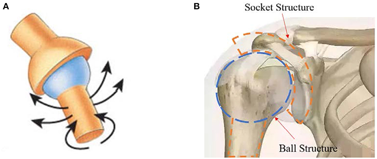
Figure 1. Ball-and-socket damper (A) and human shoulder joint (B).
The comparative performance of the ball-and-socket damper using numerical, theoretical, and experimental procedures is reported in this article. In order to estimate the characteristics of the MR fluid in the developed device, a proper relation between the shear stress and shear rate of the MR fluid should be addressed. This relation is assumed to be linear by the Bingham plastic model which has widely been used in recent years by numerous research teams for the theoretical modeling of magnetorheological fluids (Ghaffari et al., 2014). However, the shear thinning or shear thickening characteristics of MR fluids are poorly modeled by the Bingham plastic model (Wang and Liao, 2011). One major reason for this modeling shortage is that the Bingham plastic model only includes two parameters which assumes a linear fluid shear stress/shear rate relation, while the experimental results indicate that the slope of the fluid characteristics curve changes with the variation of the shear rate (Zubieta et al., 2009). Consequently, when the MR device design and the rheological conditions of the MR fluid become complicated due to the requirements of the engineering application, the Bingham plastic model was deemed to be insufficient to accurately predict the performance of the MR fluid (Zhu et al., 2012). As a result, other fluid models, such as the bi-viscous model (El Wahed, 2011), were utilized for the efficient modeling of smart fluids characteristics.
In this study, the resistive torque of the ball-and-socket damper was first estimated using a theoretical model based on the assumption of a Bingham plastic fluid characteristics for different input velocity inputs. Subsequently the device torque performance was numerically investigated using finite element analyses, which were performed using Ansys Fluent computer code with a Herschel-Bulkley fluid model. Furthermore, a dedicated experimental facility was then utilized to validate the device performance under the same sets of input conditions.
Ball-and-Socket Damper Performance Evaluation Procedures
The new smart ball-and-socket damper was designed with an opening angle (from one socket edge to another) of 126°. The MR fluid is proposed to fill the gap between the ball and socket components to control the impedance of the damper, which is proportional to the electromagnetic field intensity generated by the electromagnetic coil element that is imbedded inside the socket component, as shown in Figure 2. The overall size of the device was designed to be ~150 mm in diameter. Due to the compact size of the electromagnetic circuit of the smart damper, which was designed and optimized using electromagnetic finite element methods, the electromagnetic coil element only requires few volts to generate the magnetic field required for the excitation of the MR fluid and therefore, the smart device is considered to be electrically safe in the normal rehabilitation training environment.
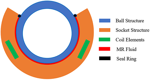
Figure 2. Section view showing the main elements of the new smart damper.
In the authors' previous study (Wang and El Wahed, 2018), it was found that the early design of the ball-and-socket damper was capable to deliver a maximum torque output of about 26 Nm using Lord Corporation commercial MR fluid, type MRF122-2ED under a magnetic flux density excitation of about 1.1 Tesla and an input angular velocity of about 1 rad/s. Accordingly, this fluid was employed in the current investigation.
In the present theoretical model, the total damping torque Tt delivered by the smart ball-and-socket damper was assumed to consist of three components, which are the controllable field-dependent torque, the viscous friction torque and the mechanical friction torque (El Wahed and Balkhoyor, 2018). The shear stress, τ of the MR fluid in the present model was accounted for using the Bingham plastic fluid model which is given by:
where η and γ are the fluid dynamic viscosity and shear rate, respectively whilst τy (H) is the fluid yield stress which depends on the magnetic field intensity H. Accordingly, the total damping torque of the device was derived into the following equation:
where r, ω, and h are the ball radius, input angular velocity and MR fluid gap size, respectively whilst φ is the socket angle which is measured from the lower end (6 o'clock) to one of the socket ends. Tf is the mechanical frictional torque, which was measured experimentally in this study and will be detailed at the end of this section. The fluid temperature was assumed to be maintained at 40°C whilst the density and viscosity of the employed fluid, which are required to complete the theoretical modeling as well as the FEM simulations of the new damper, were provided as 2,380 kg/m3 and 70 mPa.s, respectively (Adhesives Coatings Vibration Motion Control Sensing Magnetically Responsive Technologies, 2018). The yield stress of the adopted MR fluid as a function of the magnetic flux density is presented in Figure 3 (Adhesives Coatings Vibration Motion Control Sensing Magnetically Responsive Technologies, 2018). Using the estimated yield stress values (Figure 3) and Equation (2) together with the measured mechanical frictional torque, Tf, the total damping torque of the damper was then estimated theoretically for a range of magnetic flux densities of up to 0.7 Tesla and for a ball angular speed of 10 RPM.
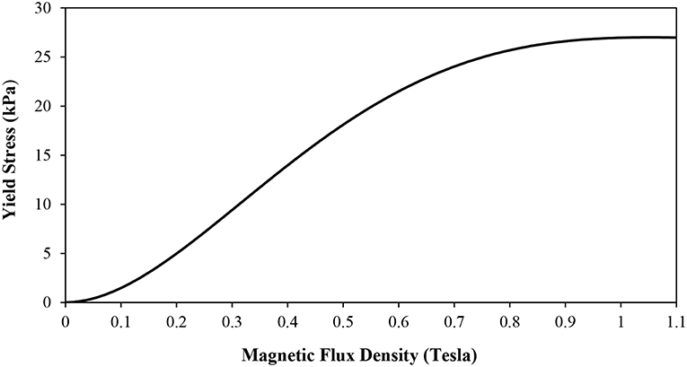
Figure 3. Yield stress vs. magnetic field density for Lord Corp MRF122-2ED fluid.
A numerical technique was then developed to estimate the performance of the developed ball-and-socket damper, which was based on finite element methods (FEM) that were performed using Ansys Fluent computer code. A model representing the fluid volume filling the gap between the ball and socket components of the damper was first created using SolidWorks CAD software, and was then exported into the Ansys Fluent environment. The magnetic flux density is assumed to be uniformly distributed along the fluid gap whilst the yield stress of the MR fluid required for the FEM simulations was again derived from the results presented in Figure 3. The fluid volume was meshed with a minimum element size of 3.5 × 10⁻⁴ m. As part of the boundary conditions set up for these simulations, the fluid volume that is adjacent to the ball component was assumed to move at the ball angular speed (sliding motion), while the surface which is in contact with the socket is assumed to be stationary (no-slip condition). The top horizontal surface of the fluid at the socket opening was also considered as a stationary wall since it is in contact with a large lip-seal that is designed to seal the fluid gap between the ball and socket. In the current FEM settings, the stationary wall boundary condition was realized when its velocity is set to zero along the three coordinates, while the moving wall condition was achieved when the applied angular speed was set in the direction along which the torque is estimated. Since the applied angular speed is low, the MR fluid flow inside the gap initiated by the ball motion was assumed to be steady, laminar, and incompressible. In addition, thermal interaction inside the MR fluid was ignored and therefore, the flow was assumed to be under adiabatic condition. The minimum pressure magnitude was also assumed to be above the fluid vapor pressure so that any cavitation was excluded from the analysis.
The MR fluid behavior was characterized using the Ansys built-in Herschel-Bulkley model which is represented by the following shear stress equation (Zubieta et al., 2009):
where k is referred to as the consistency index and n is the pseudoplastic index. The relationship between the shear stress and shear rate estimated by the Bingham plastic model is shown in Figure 4 for a magnetic flux density of 0.5 Tesla. It can be seen that the changes in the shear stress values over the shear rate range were small. This is ascribed to the fact that the fluid viscosity of 70 mPa.s, which was assumed in this model, was small and therefore, the resulting shear stress does not see dramatic changes when the shear rate changes. The lack of response in the fluid shear stress to variations in the shear rate usually affect the accuracy of the simulated performance of the MR fluid device and hence, degrade its agreement with the experimental results. However, unlike the Bingham plastic model, the shear stress-shear rate dependency is represented more accurately by the Herschel-Bulkley model through the added pseudoplastic and consistency indexes which are used to describe the shear thinning/shear thickening effects of the MR fluid. In this study, the well-recognized analysis (Zubieta et al., 2009), which was done on the same MR fluid employed in the current investigation (MRF122-2ED), was utilized for the quotation of the n and k indexes under different operation conditions. This enabled the estimation of the shear stress-shear rate characteristics of the employed MR fluid using the Herschel-Bulkley model, which are also presented in Figure 4 and compared with those estimated using the Bingham plastic model for an applied magnetic flux density of 0.5 Tesla.
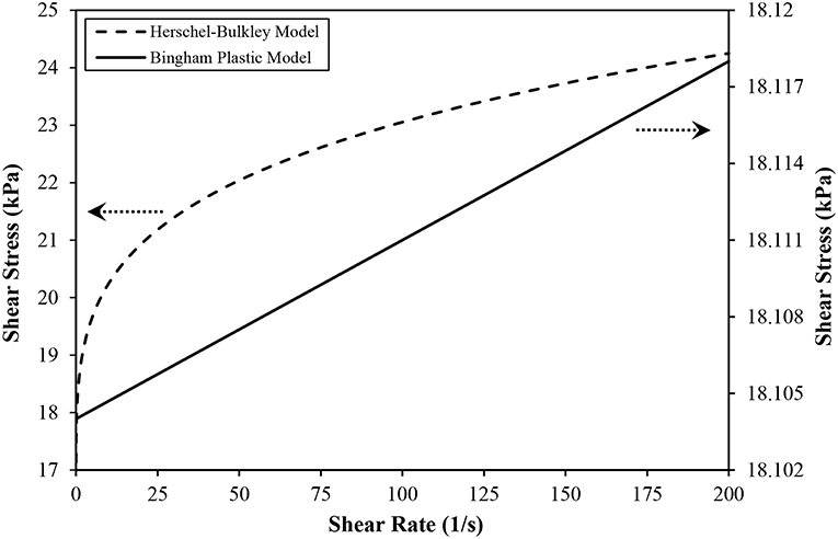
Figure 4. Shear stress vs. shear rate of MR fluid type MRF122-2ED based on Bingham Plastic and Herschel-Bulkley models for a magnetic flux density of 0.5 Tesla.
In order to experimentally verify the performance of the smart damper, a dedicated testing facility was designed and built, which comprises an AC motor with its associated speed controller type IMO Jaguar, model CUB8A-1 to supply the input rotational motion to the damper, TorqueSense Technology, model RWT320 speed and torque transducers and a magnetic particle brake type Warner Electric, model MPB240M-24-24 to apply and simulate resistive torques at the output of the smart damper, as shown in Figure 5.

Figure 5. Schematic diagram of the experimental testing rig.
In addition, a National Instruments analog-to-digital converter, model NI9205 in conjunction with a cDAQ-9172 CompactDAQ USB chassis capable of simultaneous sampling, which was controlled by a National Instruments data acquisition software, type LabVIEW running on an IBM compatible personal computer, was used to collect and record the data from the sensors and power supplies used to energize the smart damper and the magnetic particle brake. In order to allow a continuous supply of power to the electromagnetic coil of the smart damper while it is under a rotational input operation, a special arrangement was designed which consists of a plastic disc to which two copper rings were attached. The two copper rings were electrically insulated from each other and the electrical resistance between them was measured using a digital multimeter, which was found to be in access of 5 kOhm. This resistance was deemed to be high enough to prevent any charge leakage between the two copper electrodes across the plastic shank of the disc. The plastic disc was fixed on the rotating shaft just upstream the smart damper, Figure 5, and the damper's coil wires were soldered to the two copper rings. The connection of the power supply to the copper rings was achieved using two carbon brush mechanisms which were equipped with tensioning springs to ensure a continues contact with the copper rings.
The output speed and torque of the smart damper are expected to change in response to both the level of the electrical current supplied to the electromagnetic coil element of the damper and the magnitude of the resistance applied by the magnetic particle brake. In order to allow a direct comparison between the braking torque results measured experimentally and those estimated theoretically and numerically using Equation (2) and the FEM procedure, respectively the relationship between the magnetic field density generated by the damper's magnetic circuit and its coil energizing current was first established using a 3-D finite element electromagnetic approach that was executed using Ansys Workbench software. In these simulations, coil energizing currents similar to those used in the experimental assessments of the smart damper were assumed and the corresponding average magnetic field density values along an imaginary path spanning the MR fluid gap from one socket end to the other were estimated. Figure 6 shows the magnetic field density distribution along this imaginary median path inside the MR fluid gap of the ball-and-socket damper for a coil energizing current value of 1.0 A.
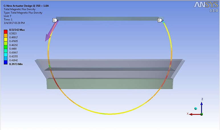
Figure 6. Magnetic field density distribution along an imaginary median path inside the MR fluid gap of the ball-and-socket damper for a coil current of 1.0 A.
Figure 7 shows the variation of the average magnetic field density simulated inside the MR fluid gap of the smart damper as a function of the damper's coil energizing current in the range between 0.25 and 2.1 A. It can be seen that a maximum energizing current of 2.1 A supplied to the electromagnetic coil of the smart damper produced an average magnetic field density in the MR fluid gap of about 1 Tesla, which is the magnetic excitation level under which the employed MR fluid becomes saturated (Adhesives Coatings Vibration Motion Control Sensing Magnetically Responsive Technologies, 2018).
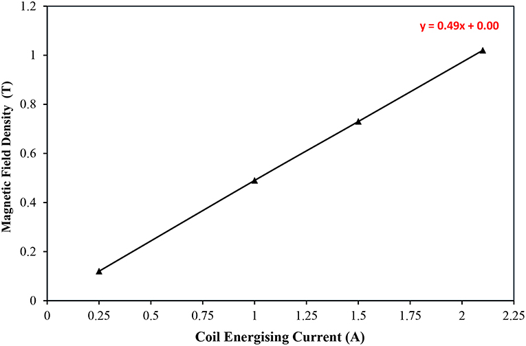
Figure 7. Variation of average magnetic field density simulated inside the MR fluid gap of the smart damper as a function of damper's coil energizing current.
The simulated data presented in Figure 7 enabled the application of coil energizing currents at the required magnetic field densities and the corresponding braking torque values of the smart ball-and-socket damper were measured for an input speed of 10 RPM. The measured torque was limited to a maximum of 20 Nm which is the maximum range of the employed torque transducers. This equipment limitation made it difficult to extend the tests beyond magnetic flux densities of about 0.6 Tesla otherwise the measured torques become higher than the maximum capability of the employed torque transducers. In addition, it is worth mentioning that velocities around 10 RPM did not produce any real difference in the measured torque values, which is expected under such low velocity range that is typical of the aimed rehabilitation application of the developed smart device. However, it was thought that despite the above hardware limitation, the reported results would still provide a useful insight into the performance of the developed device and its aimed rehabilitation application.
Finally, the mechanical friction torque, Tf, which is mainly caused by the friction between the ball and the lip-seal components of the smart damper, was measured experimentally. In this test, the socket component was fixed to a sturdy bench while a metallic shaft was attached to the center of the ball component and set at a horizontal position using a spirit level tool. Whilst the smart damper is not energized, the ball shaft was gradually loaded with static weights, Figure 8, until the ball rotates, indicating that the damper's mechanical resistance is breached. This test was repeated several times and the weight that caused the ball rotation was used to estimate the damper's mechanical torque which was found to be about 1.16 Nm. This mechanical torque value was added to the total damping torques estimated theoretically (Equation 2) and also to those simulated numerically (FEM model).

Figure 8. Test set-up for the evaluation of the mechanical friction torque.
Results and Discussion
The theoretical, numerical, and experimental procedures were then executed for the intended yield stresses which are related to the magnetic field density levels through their relationship presented in Figure 3. Figure 9 shows an isometric view of the velocity contour simulated in the fluid gap under a magnetic excitation of 0.3 Tesla when the ball was allowed to rotate with an angular speed of 10 RPM about its z axis. It can be seen that the fluid velocity varies from zero on the socket side to its maximum value on the ball side. In addition, the velocity appears to increase from the center of the socket where the fluid appears to be stationary to its maximum nearby the socket opening.
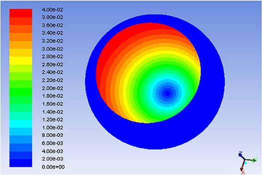
Figure 9. Isometric view of the velocity contour throughout the MR fluid volume for 0.3 Tesla fluid magnetic excitation and 10 RPM ball angular velocity.
For the same magnetic field excitation and input velocity conditions, the shear stress distribution was simulated along the fluid volume, which is shown in Figure 10. The wall shear stress appears to increase from its minimum magnitude, which occurs at the bottom end of the socket, to a maximum magnitude that occurs in areas close to the socket opening. This shear stress pattern is attributed to the fact that the fluid shearing force becomes larger with increasing angle of the socket opening, which changes from zero at the bottom of the socket to 90 degrees nearby the socket opening.
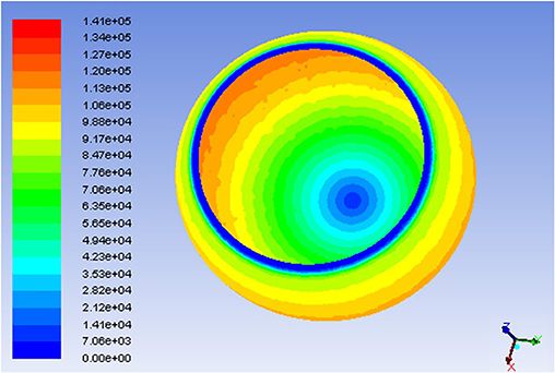
Figure 10. Shear stress distribution along the MR fluid volume for 0.3 Tesla fluid magnetic excitation and 10 RPM ball angular velocity.
The damping torque of the smart damper as a function of the magnetic flux density was estimated using the three employed techniques for a rotational speed of 10 RPM and the results are shown in Figure 11.
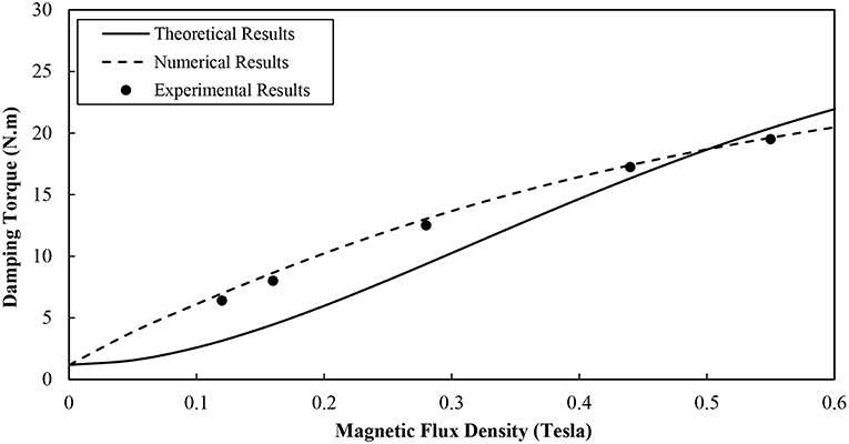
Figure 11. Damping torque vs. magnetic field density of the smart damper for angular speed of 10 RPM.
It can be seen that higher magnetic flux densities and hence larger fluid yield strengths caused the smart damper to produce higher damping torques. The damping torques appeared to increase almost linearly with the magnetic flux density particularly the current range of the fluid magnetic excitation is far from those magnetic field levels that cause fluid saturation. However, the simulated damping torque results seem to be closer to those obtained experimentally in comparison with the theoretical results. This is ascribed to the fact that the numerical approach with its employed Herschel-Bulkley model contributed to a more accurate estimation of the fluid shear stress in comparison with those produced theoretically in association with the Bingham plastic model (Figure 4). It could also be seen in this figure that when the magnetic field density is <0.4 Tesla, the theoretical results with their assumed Bingham plastic fluid characteristics seem to depart further from the experimental results. This might be caused by the fact that the shear thinning effect of the MR fluid is more obvious when the applied magnetic field is weak, which is not accounted for by the utilized Bingham plastic model unlike the Herschel-Bulkley model which takes care of this effect.
Furthermore, a deviation of 5–7% was observed between the experimental and numerical results which could be ascribed to the fact that although the electromagnetic circuit of the smart damper was designed through the electromagnetic FEM to generate a uniform magnetic field along the fluid gap, the prototype smart damper, due to various experimental deviations, may not exactly maintain this field uniformity. Overall, and according to the three assessment approaches, the smart damper appears to deliver a damping torque of about 22 Nm under a magnetic excitation of about 0.6 Tesla.
Conclusion
In this study, theoretical, numerical, and experimental approaches were developed to assess the performance of a novel smart MR fluid damper which was designed with a ball and socket structure to enable a multi-degrees-of-freedom device output. The theoretical model assumed a Bingham plastic fluid characteristics whilst the numerical technique employed the Herschel-Bulkley model which resulted in a more accurate fluid shear stress estimation. The mechanical torque of the device, which was caused by the friction between the ball and lip-seal components, was also measured experimentally, and was added to the theoretical and numerical torque results. A dedicated testing facility was utilized to verify the performance of the smart damper, which was found to be in a good agreement with the simulated device performance in comparison with that estimated theoretically.
Author Contributions
All authors listed have made a substantial, direct and intellectual contribution to the work, and approved it for publication.
Conflict of Interest Statement
The authors declare that the research was conducted in the absence of any commercial or financial relationships that could be construed as a potential conflict of interest.
References
Adhesives Coatings Vibration Motion Control Sensing Magnetically Responsive Technologies (2018). LORD Corp, Lord.com, [Online]. Available online at: https://www.lord.com/ (Accessed February 05 2018).
Chrzan, M., and Carlson, J. (2001). MR fluid sponge devices and their use in vibration control of washing machines. Smart Struct. Mater. 4331, 370–379. doi: 10.1117/12.432719
Dyke, S., Spencer, B., Sain, M., and Carlson, J. (1998). An experimental study of MR dampers for seismic protection. Smart Mater. Struct. 7, 693–703. doi: 10.1088/0964-1726/7/5/012
El Wahed, A. (2011). The influence of solid-phase concentration on the performance of electrorheological fluids in dynamic squeeze flow. Mater. Design 32, 1420–1426. doi: 10.1016/j.matdes.2010.09.003
El Wahed, A., and Balkhoyor, L. (2015). Magnetorheological fluids subjected to tension, compression, and oscillatory squeeze input. Smart Struct. Syst. 16, 961–980. doi: 10.12989/sss.2015.16.5.961
El Wahed, A., and Balkhoyor, L. (2016). Characteristics of magnetorheological fluids under single and mixed modes. Proc. Institut. Mech. Eng. C 231, 3798–3809. doi: 10.1177/0954406216653621
El Wahed, A., and Balkhoyor, L. (2018). The performance of a smart ball-and-socket actuator applied to upper limb rehabilitation. J. Intell. Mater. Syst. Struct. 29, 2811–2822. doi: 10.1177/1045389X18780349
El Wahed, A., and McEwan, C. (2011). Design and performance evaluation of magnetorheological fluids under single and mixed modes. J. Intell. Mater. Syst. Struct. 22, 631–643. doi: 10.1177/1045389X11404453
Ghaffari, A., Hashemabadi, S., and Ashtiani, M. (2014). A review on the simulation and modeling of magnetorheological fluids. J. Intell. Mater. Syst. Struct. 26, 881–904. doi: 10.1177/1045389X14546650
Goncalves, F., and Carlson, J. (2009). An alternate operation mode for MR fluids—magnetic gradient pinch. J. Phys. 149:012050. doi: 10.1088/1742-6596/149/1/012050
Nguyen, Q., and Choi, S. (2009). Optimal design of MR shock absorber and application to vehicle suspension. Smart Mater. Struct. 18:035012. doi: 10.1088/0964-1726/18/3/035012
Olabi, A., and Grunwald, A. (2007). Design and application of magneto-rheological fluid. Mater. Design 28, 2658–2664. doi: 10.1016/j.matdes.2006.10.009
Wang, D., and Liao, W. (2011). Magnetorheological fluid dampers: a review of parametric modeling. Smart Mater. Struct. 20:023001. doi: 10.1088/0964-1726/20/2/023001
Wang, H., and El Wahed, A. (2018). “CFD simulation of a smart magnetorheological fluid actuator,” in ACTUATOR 2018-16th International Conference on New Actuators, Bremen.
Wang, X., and Gordaninejad, F. (2000). Field-controllable electro- and magneto-rheological fluid dampers in flow mode using Herschel-Bulkley theory. Smart Struct. Mater. 3989, 232–244. doi: 10.1117/12.384564
Wereley, N., Cho, J., Choi, Y., and Choi, S. B. (2007). Magnetorheological dampers in shear mode. Smart Mater. Struct. 17:015022. doi: 10.1088/0964-1726/17/01/015022t
Zhu, X., Jing, X., and Cheng, L. (2012). Magnetorheological fluid dampers: a review on structure design and analysis. J. Intell. Mater. Syst. Struct. 23, 839–873. doi: 10.1177/1045389X12436735
Keywords: MDOF smart damper, magnetorheological fluids, Herschel-Bulkley model, Bingham plastic model, finite element modeling
Citation: El Wahed AK and Wang HC (2019) Performance Evaluation of a Magnetorheological Fluid Damper Using Numerical and Theoretical Methods With Experimental Validation. Front. Mater. 6:27. doi: 10.3389/fmats.2019.00027
Received: 05 December 2018; Accepted: 08 February 2019;
Published: 28 February 2019.
Edited by:
Seung-Bok Choi, Inha University, South KoreaReviewed by:
Tianhong Yan, China Jiliang University, ChinaJianbo Yin, Northwestern Polytechnical University, China
Copyright © 2019 El Wahed and Wang. This is an open-access article distributed under the terms of the Creative Commons Attribution License (CC BY). The use, distribution or reproduction in other forums is permitted, provided the original author(s) and the copyright owner(s) are credited and that the original publication in this journal is cited, in accordance with accepted academic practice. No use, distribution or reproduction is permitted which does not comply with these terms.
*Correspondence: Ali K. El Wahed, YS5lbHdhaGVkQGR1bmRlZS5hYy51aw==