 Enrico Babilio
 Raffaele Miranda
 Fernando Fraternali
95% of researchers rate our articles as excellent or good
Learn more about the work of our research integrity team to safeguard the quality of each article we publish.
Find out more
ORIGINAL RESEARCH article
Front. Mater. , 06 February 2019
Sec. Mechanics of Materials
Volume 6 - 2019 | https://doi.org/10.3389/fmats.2019.00007
This article is part of the Research Topic Multiscale lattices and composite materials: Optimal design, modeling and characterization View all 15 articles
This paper presents a mechanical study on the use of tensegrity lattices for the design of energy efficient sun screens, inspired by the dynamic solar façades of the Al Bahar Towers in Abu Dhabi. The analyzed screens tassellate origami modules formed by 12-bar and 3-string tensegrity systems. The actuation of each module is controlled through the stretching of the perimeter strings, which form macro-triangles moving parallel to the building, while all the bars and the fabric mesh infills form micro-triangles that are allowed to move rigidly in space. We developed an analytic formulation of the deformation mapping associated with such an actuation motion, giving rise to a morphing-type behavior. We also estimated the energy required to activate the analyzed shading system, and established a comparison between its weight and that of the original screens of the Al Bahar Towers. The proposed tensegrity design concept leads to the realization of shading screens that are markedly lightweight, operate on very low energy consumption and can be usefully employed to harvest solar and wind energies.
Sustainable engineering and architecture aim at designing buildings with limited environmental impact and improved energy efficiency, comfort and indoor air quality, through appropriate construction techniques (refer, e.g., to Schittich, 2003; Quesada et al., 2012a,b and references therein). A sustainable design approach looks at the optimal design and control of natural ventilation systems, building orientation and shading, through passive and/or active techniques. The latter calls for the incorporation of home automation systems and renewable energy supplies within the building, typically in correspondence with the buildings “skin” (Kuhn et al., 2010; Balduzzi et al., 2012; Bai et al., 2018).
The European Union (EU) requires Member States to develop long-term national plans to encourage efficient re-development of buildings and reduction of CO2 emissions by between 80% and 85% compared to 1990 Directive UE (2018/844). The EU policy for the energy efficiency of buildings is aimed at formulating long-term strategies that facilitate the transformation of residential and non-residential buildings, into efficient and decarbonised structures by 2050, with the aim of achieving almost zero net energy consumption (Lombard et al., 2010). The demand for energy savings and the reduction of CO2 emissions has called for the use of new interactive building envelopes. Such active façades must respond to the variations of the external climatic conditions through automatic control devices, with the aim of significantly optimizing the energetic performance of the building.
Recent research has proposed the use of tensegrity structures for the construction of renewable energy supplies forming dynamic envelopes of energy efficient buildings, due to the special ability of such structures to act as deployable systems, which can also convert the strain energy stored in cables, into electric power (Skelton and de Oliveira, 2010; Fraternali et al., 2015; Cimmino et al., 2017). Tensegrity systems are truss structures whose compressive members (or bars) can be described as rigid of partially deformable bodies, while the tensile members (cables or strings) exhibit high compliance. The strings are usually pre-stretched, and are inserted into the structure in order to stabilize the compressed members (Skelton and de Oliveira, 2010).
This paper continues and significantly expands the study initiated in Fraternali et al. (2015), on the use of tensegrity systems for the actuation of dynamic sun screens. We design tensegrity screens that mitigate air conditioning consumption resulting from direct exposure to solar rays of an energy efficient building, and derive the exact kinematics of such structures under operating conditions. We also study the stress response of the examined tensegrity systems to wind loading, and quantify their lightweight nature and the energy cost required for their activation. The geometry of the solar façade analyzed in this work is inspired by that of the sun screens protecting the Al Bahar Towers in Abu Dhabi, United Arab Emirates, designed by Aedas Architects-UK (now AHR) in 2007, in collaboration with the Arup Group (Karanouh and Kerber, 2015; Attia, 2017). These towers are 29-story skyscrapers that host the headquarters of the Abu Dhabi Investment Council's and the Al Hilal Bank. The screens of the Al Bahar Towers mimic the shading lattice-work “ashrabiya” through “origami” panels that are dynamically opened at night, and are progressively closed during daylight hours (Karanouh and Kerber, 2015). We refer to the shading façade designed by Aedas architects as the “Al Bahar Screen” (ABS) throughout this paper.
The tensegrity solution that we propose for the re-design of the ABS controls the tension in selected cables forming the shading structure. It is aimed at demonstrating that the use of tensegrity concepts for the design of active solar façades leads to lightweight morphing systems that require minimal storage of internal energy and reduced operation costs. Such a design can easily be generalized to dynamic skins of energy efficient buildings featuring different topologies, upon retaining the use of morphing architectures (Fleck et al., 2010), and deployment mechanisms controlled through cable stretching and relaxation (Fraternali et al., 2015). We label the sun screen designed in the present work as the “Tensegrity Al Bahar Screen” (TABS).
The structure of the paper is as follows. We begin by reviewing the AHR design of the ABS in section 2. Next, we move on to design a basic TABS module, by developing an analytic formulation of the kinematics of such a structure. We prove that the employed actuation mechanism requires the deformation of a limited number of members, and exhibits a morphing-type response (section 3). The stress analysis of the TABS module is conducted in section 4, while an estimate of the energy costs associated with its actuation is presented in section 5. We highlight the main advantages of the TABS technology in section 6, where we also draw potential future extensions of the present research.
The biggest challenge that contemporary architecture has to address, in order to make progress in sustainability, is to optimize natural resources and minimize energy consumption. To provide the best answer to this need it is necessary to design flexible and reconfigurable building envelopes able to dynamically react on the base of the evolution of weather and environmental conditions (Figure 1). The adaptive architecture of the Al Bahar tower façade by AHR develops a new design approach based on structural systems that can change their shape by reacting to the surrounding environment. The heart of the Al Bahar tower project consists of a modern-day re-interpretation of the traditional “mashrabiya” shading system. The latter is a passive shading technology typical of the Arab world, which consist of perforated wooden screens forming wonderful geometric patterns, which reduce solar gain and mitigate air conditioning consumption resulting from direct exposure to solar rays (Armstrong et al., 2013).
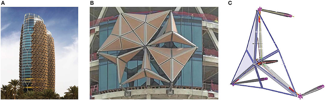
Figure 1. (A) Illustration of the Al Bahar towers in Abu Dhabi. (B) detail of a module of the ABS (picture taken during the mounting of the screens). (C) ABS actuation mechanism (reproduced with permission from Karanouh and Kerber, 2015).
The peculiarity of the adaptive ABS consists in no longer interpreting the mashrabiya as a static and two-dimensional system, but rather as a façade design approach generating three-dimensional origami shapes (Figure 1B), whose motion in space can be controlled by sensors and actuators during daylight hours (typically, from 9 a.m. through 5 p.m.) (Al-Kodmany, 2016). The evaluation of the insulation property of a façade, the so-called U-value (defined as the amount of heat passing per unit of surface of the screen, under one Kelvin temperature gradient between indoor and outdoor), is a topic of paramount interest for the architects and engineers operating in the field. Energy studies conducted on the ABS lead to conclude that the overall U-value of this building envelope is equal to 2.0 W/m2K, which corresponds to that of a solid brick wall (Designing Buildings Wiki)1. The origami panels are covered by a polytetrafluoroethylene (PTFE) coated fiber mesh, which reduces the G-value of the façade more than 50% (i.e., the ratio between the total solar heat gain and the incident solar radiation), as compared to a glazed envelope (Karanouh and Kerber, 2015). The activation of the ABS is driven by a centrally positioned electric screw-jack linear actuator (piston-actuated computer-controlled technology) that operates on low energy consumption. The linear actuator stroke reaches up to 1,000 mm, which folds the panels and provides up to 85% clear opening area (Armstrong et al., 2013) (Figure 1C). The structural elements of the ABS are made of duplex (austenitic-ferritic) stainless steel supporting frames and Aluminum dynamic frames, with each triangle of the screen covered by a glass fiber panel (Figure 1B) (Karanouh and Kerber, 2015; Attia, 2017). The umbrella-like module of the ABS has a height of 4,200 mm, and a width ranging between 3,600 and 5,400 mm. In total, each tower has 1,049 shading modules, each weighing a 1.5 tons (Armstrong et al., 2013; Attia, 2017).
The TABS concept is illustrated in Figure 2, with reference to a basic module of the structure. The analyzed module is composed of six “micro-triangles,” and is such that its boundary forms a “macro-triangle” when projected onto a plane parallel of the building façade (umbrella-like module). The activation mechanism of the TABS module is driven by a linear actuator, which stretches the perimeter strings, by pushing against a vertex of the macro-triangle along its bisector, in parallel to the building façade. The mechanism is guided by two linear springs controlling the in-plane displacements of the other two vertices of the macro-triangle, and a telescopic collar guiding the out-of-plane displacement of the center of mass of the module (Figure 2). It is worth remarking that such a “tangentially” activated mechanism substantially differs from that driving the ABS module, since the latter pushes orthogonally to the building façade, against the center of mass of the module (Armstrong et al., 2013; Karanouh and Kerber, 2015; Attia, 2017). We study in section 3.1 the existence of a deformation mapping of the TABS module, which corresponds to the described actuation mechanisms and ensures that all the micro-triangles move rigidly in space. Such a morphing-type behavior (Hutchinson and Fleck, 2006; Fleck et al., 2010) induces minimal storage of internal energy during the actuation phase, and ensures high stiffness and stability when the actuation mechanism is not triggered (cf. Sections 4, 5).
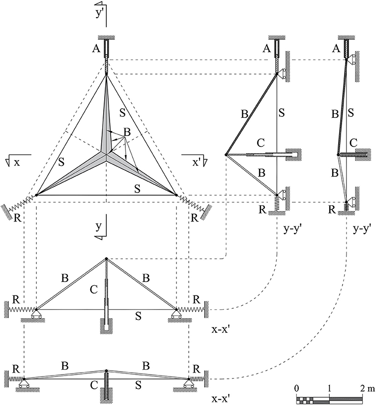
Figure 2. Schematic views of the TABS concept: top view and mid-plane sections (in two different configurations): A, linear actuator; B, bars; C, telescopic collar; R, elastic restraints; S, perimeter strings. Restraints are idealized and not reported in scale.
The model of the TABS adopted in following analytical and numerical developments is reported in Figure 3, to which we refer for notation. The module is described as a tensegrity system formed by 3 strings parallel to the building façade and aligned with the edges of the macro-triangle (red-colored members), and 12 bars forming the edges of the micro-triangles (black-colored members). Figure 3 depicts the completely folded configuration (Figure 3A) of the tensegrity model, which we assume as reference, and the unfolded, perfectly flat configuration (Figure 3B). The TABS model is formed by seven nodes (numbered from 0 to 6 in Figure 3), for a total of 21 degrees of freedom (ndof = 21). The adopted Cartesian frame is reported in Figure 3.
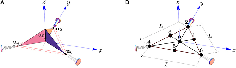
Figure 3. Reference (A) and deformed (B) configurations of a tensegrity model of the TABS module. (A) shows the folded configuration of the structure corresponding to the fully opened screen. (B) depicts the flat configuration (fully closed screen), where the module reduces to an equilateral triangle with side L. Nodes 2, 4, and 6 are mutually connected through deformable strings (red-colored members), which are at rest in the reference configuration, and fully stretched in the flat configuration. The strings are superimposed to the perimeter bars in the flat configuration (B).
In agreement with the activation mechanism described above, the boundary conditions (BCs) of the TABS module are as follows
where ui(x), ui(y) and ui(z) are the Cartesian components of the nodal displacement vector ui exhibited by the generic node i. The BCs (1) must be complemented by three additional equations, respectively associated with the linear actuator acting on node 2, and the two springs acting on nodes 4 and 6 (actuation constraints, cf. Section 3.1).
Let us investigate on the existence of a rigid body transformation of the TABS deprived of external constraints, which cause stretching (positive) strains only in the perimeter strings connecting nodes 2, 4, and 6 (cf. Figure 3), measured from the fully-folded configuration (rest configuration), while keeping all the bars undeformed.
The rigid-body deformation mapping under investigation is constrained by the 11 BCs defined above, plus 12 rigidity constraints associated with the bars forming the module. In agreement with BCs (1), the displacement vector of node 2 attached to the linear actuator of the TABS module is given by
U denoting the time-dependent norm of such a displacement, which is measured from the fully folded configuration. Due to constructive needs, we require that the researched rigid body transformation is such that the displacements of nodes 4 and 6 exhibit the same norm U of u2 (due to symmetry), and nodes 5, 3, and 1, respectively move along the y-axis (i.e., the projected 5–2 edge onto x, y-plane, see Figure 3), the projected 3–6 edge (aligned with the y-axis rotated of π/3), and the projected 1–4 edge (aligned with the y-axis rotated of −π/3). Our next developments will show that such assumptions are equivalent to the enforcement of the actuation constraints at the vertices of the TABS module. Overall, the deformation mapping associated with the researched rigid body transformation of the TABS is described by Equation (2), and the following additional displacement laws
where α, β, and γ are unknown functions of U, to be determined on enforcing rigidity constraints on all the bars. In the completely folded and flat configurations it trivially results
and
Let us label the position vectors of the generic point i in reference and deformed configurations as Xi and xi, respectively. The rest and deformed lengths of the eth element attached to nodes i and j are given by
where dot symbol (·) denotes the scalar product between vectors. The rigidity constraints to be considered require that it results
in correspondence to all the bars (here, squared lengths are used for algebraic convenience). It is easily shown that the enforcement of such constraints leads us to the following system of three independent (nonlinear) equations
which admit four distinct sets of solutions for α, β and γ, as it can be verified through the use of the Solve function of Mathematica®. Three of such solutions violate Equations (5) and (6), while the unique admissible solution has the following expression
We are therefore led to the following expression of the 7 × 3 matrix that collects the deformed coordinates of nodes from 0 to 6 of the TABS module,
Equation (12) gives the analytic description of the researched actuation motion of the TABS module. Graphic illustrations of such a transformation are provided in Figures 4–6, on assuming L = 4.55 m, as in the ABS (Karanouh and Kerber, 2015), and the displacement U of the actuated node as order parameter. It is worth noting that the elongation (i.e., the change in length) exhibited by the perimeter strings is equal to , which corresponds to the engineering strain ε = 2U/L. For U = (perfectly flat configuration) the engineering strain exhibited by the perimeter strings is considerably high, and approximately equal to 15%. In correspondence to the examined value of L, it is immediate to verify that it results that = 0.352 m, and that the norm u0 of the out-of-plane displacement of node 0 is equal to 1.313 m (unfolding displacement of the umbrella module).
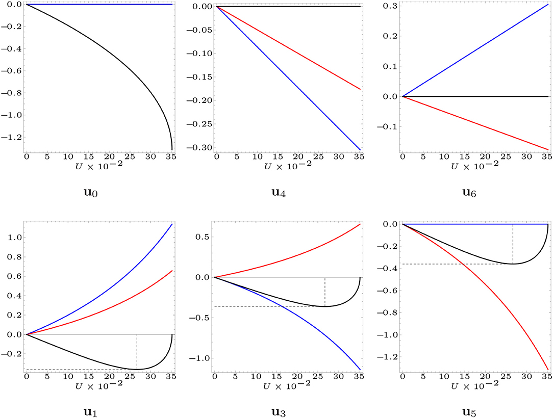
Figure 4. Nodal displacements from the fully folded configuration exhibited by the non-actuated nodes of the TABS module, assuming L = 4.55 m. The Cartesian components of the nodal displacements along the x-axis are marked in blue, while the components along the y-axis are marked in red, and those along the z-axis are marked in black.
Figure 4 shows that the mid nodes 1, 3, and 5 of the edges of the macro triangle exhibit negative z-displacements, which implies that such nodes move toward the building façade during the actuation of the TABS (cf. also Figure 6). It is useful to compute the minimum value of the z displacement of such nodes during the TABS actuation, with aim of sizing the gap to be allowed between such a structure and the building façade. Making use of Equation (12) and the Solve function of Mathematica®, it is not difficult to verify that it results du1(z)/dU = 0 for U = U° = 0.059L, and u1(z)min = −0.079L. In particular, for L = 4.55 m, one gets U° = 0.268 m, and u1(z)min = −0.359 m. We therefore conclude that the TABS module must be placed at least at ~36 cm from the building façade. It is worth noting that the Aedas design of the Al Bahar Towers places the ABS at 2.8 m from the façade of the towers, for window cleaning and shading system maintenance (Armstrong et al., 2013; Attia, 2017).
The present Section is devoted to the computation of the axial forces carried by the members of the TABS model under the actuation motion (section 4.1), and wind-induced forces (section 4.2). For the sake of simplicity, and considering the common operation times of the analyzed sun screens (Armstrong et al., 2013; Karanouh and Kerber, 2015; Attia, 2017), we assume that the TABS structure reacts to such loading conditions through a quasi-static deformation process, by neglecting inertial and damping (i.e., dynamical) effects.
Upon extending the mechanical theory presented in Modano et al. (2018) and Mascolo et al. (2018) to the TABS model under consideration, we describe the generic member of such a structure as a linear spring that carries an axial force te obeying the following constitutive law
where it results
Ee denoting the Young's modulus of the material, and Ae denoting the cross section area.
Our physical model of the TABS assumes L = 4, 550 mm (cf. Section 3.1), and makes use of Aluminum alloy hollow tubes for the bars and nylon-fiber ropes for the strings, whose properties are given in Tables 1, 2, respectively. Aluminum bars were chosen because of their lightweight nature and high corrosion resistance (Mazzolani, 1994), while nylon-fiber ropes were selected due to the fact that such elements combine a considerably low Young's modulus, elastic elongation to failure (or yield strain) slightly greater than the deformation needed for actuation purposes (≈15%, cf. Section 3.1), and considerably high tensile strength (see Table 2, where the given mechanical properties have been imported from a web source, 20182; refer, e.g., to Nylonrope, 2018 for fabrication information). Other possible choices for the strings of the TABS may employ suitable natural or artificial fibers (see Naveen et al., 2018 and references therein), or rubber materials (Soru, 2014). The adopted physical model adequately approximates the rigid-elastic response analyzed in section 3.1 (rigid bars and flexible strings), since it includes bars exhibiting axial stiffness much greater than the axial stiffness of the strings (EbAb = 493.625EsAs, subscripts b and s denoting bars and strings, respectively, see Tables 1, 2).
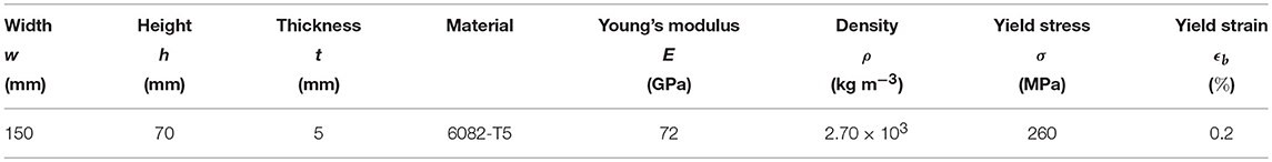
Table 1. Geometric and mechanical data of 6082-T5 Aluminum bars.
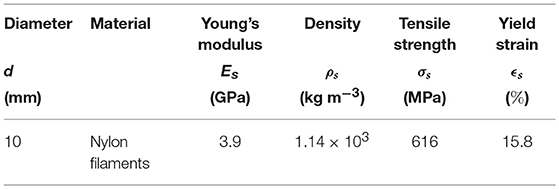
Table 2. Geometric and mechanical (effective) data of (nylon-fiber ropes).
The total potential energy of the TABS model under consideration is given by
where K denotes the stiffness of the actuation springs applied to nodes 4 and 6 (cf. Figure 2) that we assume equal to 67 kN m−1 (K = EsAs/L). The equilibrium equations of the TABS model under arbitrarily large nodal displacements ûj (j = 1, …, ndof) are obtained by imposing stationarity of the total potential energy (Equation 15) with respect to such quantities, which leads us the following system of equations
Here, the index e runs from one to the total number of members m, which include bars, perimeter strings and actuation springs, while the quantity denotes a scalar multiplier of the nodal forces wj (j = 1, …, ndof).
We computed the solution of the nonlinear system (Equation 16) through the path-following algorithm described in Mascolo et al. (2018), with reference to two distinct deformation processes. The first process is aimed at estimating the mechanical response of the examined physical model under the actuation motion studied in section 3.1 (cf. Section 4.1). In the second process, the structure is deployed from the fully-folded configuration to the almost closed configuration corresponding to U = 0.95 , and next is subject to wind-forces acting on such a configuration (cf. Section 4.2). The reason for applying wind forces on the configuration with U = 0.95 (instead of the fully flat configuration corresponding to U = ) is two-fold, technological and aesthetic. From a technological point of view, we note that the fully flat configuration of the TABS module is not completely deployable, due to the finite size of the bars forming such a system, which unavoidably get in touch before the configuration with U = is reached (see Figures 1, 5). Regarding aesthetic issues, we observed that having a “technologically closed” configuration of the TABS module, which is not perfectly flat, ensures that such a structure has an origami shape in correspondence to all the steps of the actuation motion (cf. Figures 5, 6), as in the original ABS design (Karanouh and Kerber, 2015; Attia, 2017).
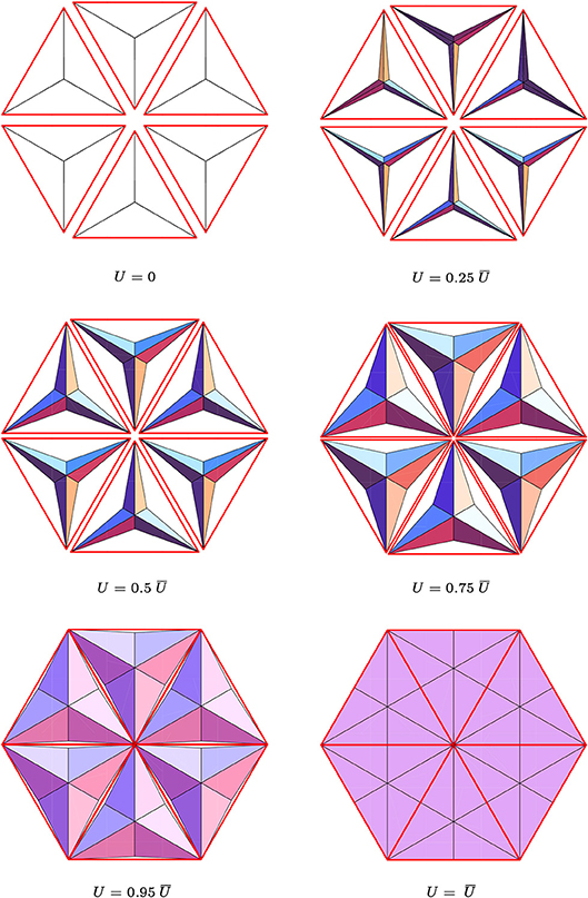
Figure 5. Top views of different frames of the TABS actuation motion. (see the Supplementary Video for an animation of the TABS actuation).
Figure 6. Side views of different frames of the TABS actuation motion (see the Supplementary Video for an animation of the TABS actuation).
Let us focus our attention on the forces carried by the perimeter strings in correspondence with the fully-flat configuration with U = , and the almost closed configuration with U = 0.95 , alongside the actuation motion of the TABS. It is an easy task to compute such quantities using the path-following algorithm described in Mascolo et al. (2018), or, alternatively, by simply observing that the elongation of the perimeter strings is equal to in the generic, deformed configuration of the TABS (cf. Section 3.1). The forces, strains and stresses carried by the perimeter strings in the above configurations of the TABS are shown in Table 3. It is immediate to verify that the stresses carried by the strings in correspondence to the analyzed configurations, are slightly lower than the tensile strength of 616 MPa of the adopted nylon-fiber ropes (cf. Table 2).
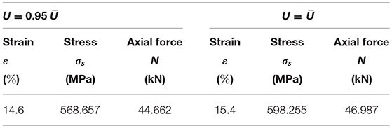
Table 3. Strain, stress and axial force carried by the generic perimeter string in the almost fully-flat (U = 0.95 ) and fully-flat (U = ) configurations.
The use of the path-following procedure outlined in section 4 leads us to obtain the nodal forces acting on the TABS module for U = and U = 0.95 , which are shown in Table 4. The force acting on the node 2 will be employed in section 5 to select the linear actuator to be applied to the TABS module under consideration.
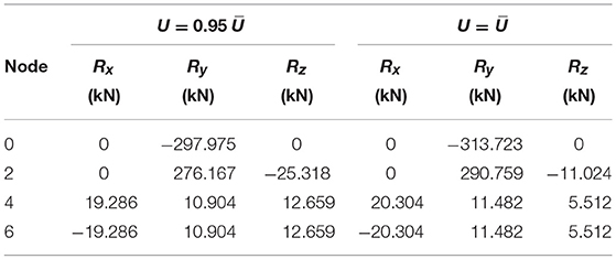
Table 4. Nodal forces acting in the almost fully-flat (U = 0.95 ) and fully-flat (U = ) configurations.
Relevant external loads for the stress analysis of the TABS are those induced by the action of positive and negative (i.e., suction) wind pressures on the closed configuration of the structure (Karanouh and Kerber, 2015). It is known that wind induces dynamic, intrinsically random, and time-dependent loads on wind-exposed structures, whose direction is variable in time and influenced by a number of different factors (refer, e.g., to the European standard for wind actions EN 1991-1-4, 2005).
By addressing a dynamical treatment of wind forces on the TABS to future work, in the present study we focused our attention on the equivalent static wind load analysis, which is contemplated by technical standards (EN 1991-1-4, 2005; Blaise and Denoël, 2013). We considered a fixed direction of wind forces parallel to the z-axis of the adopted Cartesian frame (Figure 3). Making use of the results of wind tunnel tests on full-scale prototypes of the ABS presented in Attia (2017) and Karanouh and Kerber (2015), we assumed the wind pressure = 3.5 kPa over the projection of the screen onto the x, y-plane. Said ||·|| the Euclidean vector norm, × the vector product symbol, and introduced two vectors ap and bp lying along the edges of the generic micro-triangle (or panel) forming the TABS, the surface area Ap of such an element was computed as follows
while its unit normal is given by
The wind force acting over the generic panel p, along its normal vector, was computed through (EN 1991-1-4, 2005; Blaise and Denoël, 2013)
ez denoting the unit vector along the z-axis, and ⊗ denoting the tensor product symbol. The wind force acting on the generic node of the TABS was finally obtained as follows
ni denoting the number of panels attached to node i.
As already anticipated, we applied both positive and negative wind pressure forces on the almost flat configuration of the TABS corresponding to U = 0.95 . An application of the path-following algorithm described in Mascolo et al. (2018) lead us to the results reported in Tables 5, 6, which show the axial strains, stresses and forces carried by all the members of the TABS module under such loading conditions, assuming tensile strains, stresses and forces as positive. The results shown in Tables 5, 6 highlight that the stresses carried by the strings and bars are lower than the corresponding yield strengths, and that the axial forces carried by the bars, when negative, are lower than the local Eulerian buckling loads. In particular, the axial stresses carried by the bars are significantly lower than the yield stress of 260 MPa. We accept that the bars can be loaded either in compression (negative bar forces) or in tension (positive bar forces), while we requite that the strings must always work in tension. Tables 3, 5, and 6 show that the strings of the TABS module (members 2–6, 6–4, and 4–2) always carry positive forces. This is due to the actuation mechanism of the module, which leads the strings to be fully stressed under a tensile strain of the order of 15% in the (theoretically) fully closed configuration of the screen. It is worth remarking that the marked stretching of the strings in the closed configuration of the system, confers significant geometric stiffness (Fraternali et al., 2015) to such elements, preventing them from going slack, e.g, under the action of suction wind forces.
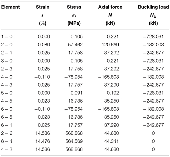
Table 5. Strains, stresses and axial forces produced by the application of positive wind pressure forces on the TABS configuration corresponding to U = 0.95 .
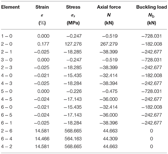
Table 6. Strains, stresses and axial forces produced by the application of negative wind pressure forces on the TABS configuration corresponding to U = 0.95 .
The present Section is primarily devoted to estimate the energy cost associated with the operation of the linear actuator applied to node 2 (see Figure 3) of the system illustrated in Figure 2. We begin by sizing such an actuator, using a commercially available, electro-mechanical actuator of the Rolaram® series by Power Jacks (2018). The activation force (or dynamic load) prescribed to the actuator is assumed coincident with the nodal force computed at node 2 of the configuration with U = 0.95 , which is equal to Fa = 290.759 kN (cf. Table 4). Table 7 shows different Rolaram® actuators ensuring dynamic load capacity of the same order of magnitude of Fa. The activation time of such actuators have been computed through the product of the inverse of the actuation speed by the stroke U = 0.95 ≈ 334 mm, while the corresponding energy consumptions have been computed by multiplying the activation time by the power requested by the actuator.
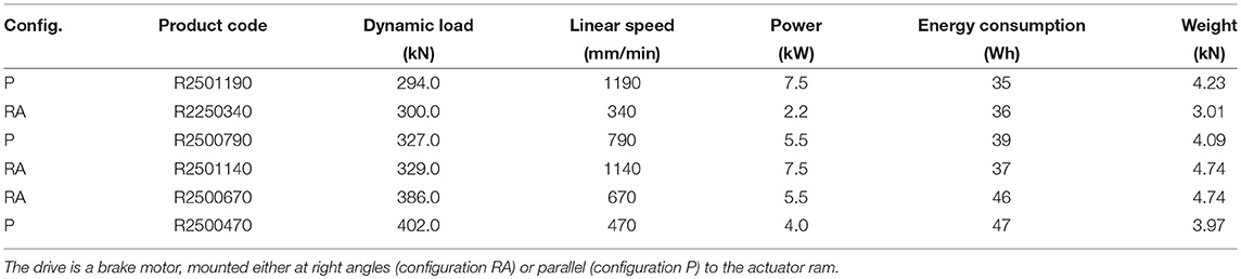
Table 7. Main parameters of Rolaram® linear actuators.
The device that is most suited for our scopes in Table 7 is the actuator Rolaram® R2501190, which shows 294 kN dynamic loading capacity and maximum stroke of 3,500 mm (Power Jacks, 2018). The activation time of such an actuator, which is required to take the TABS module from the fully folded to the almost flat configuration (U = 0.95 ), can be rather short, and approximately equal to 17 s. The corresponding energy consumption is markedly low, equal to that needed to keep a light bulb of 35 W lit for 1 h. Obviously, such an activation time can be suitably relaxed for operational purposes, as a function of the programmed opening and closure times of the screen. We wish to remark that the “parallel” actuation mechanism of the TABS module analyzed in the present work contemplates a stroke that is equal to 33 % of that needed to actuate the analogous module of the ABS via a central piston (1,000 mm, cf. Karanouh and Kerber, 2015; Attia, 2017).
We close the present section by presenting a comparison between the weight of the examined physical module of the TABS and that of the ABS module designed by Aedas architects (Alotaibi, 2015). Figure 7 shows a graphical comparison of ABS and TABS umbrella modules, highlighting the different sizes of the structural members that form such systems. It is useful to observe that the ABS solution presents different families of bars: primary bars placed behind the screens supporting the actuation mechanism; Aluminum frames supporting the panels; stabilizers connecting the first two sets of bars; and cantilever struts separating the screens from the façade of the towers (see Figure 1C, and Figure 17 of Karanouh and Kerber, 2015). The total weight of the ABS module is reported as approximately equal to 1.5 tons (14.71 kN) in Attia (2017) and Armstrong et al. (2013).
Figure 7. Graphical comparison between ABS (left) and TABS (right) modules.
The TABS module is instead formed by 12 bars placed along the perimeters of the six micro-triangles forming the system (Figures 2, 3). The weight of the structural part of the TABS module equipped with Aluminum bars and nylon-fiber ropes (see data in Tables 1, 2) is easily computed, and amounts to 1.43 kN. We safely doubled such a weight, in order to grossly account for the additional weights of joints, rails, springs and secondary elements. The weight of the infill panels amounts to about 0.13 kN, on using PTFE panels, as in the original ABS design (Armstrong et al., 2013; Karanouh and Kerber, 2015; Attia, 2017), which have self weight per unit area of 0.015 kN m−2 and cover an area of about 9 m2 per module (see e.g., Structurflex, 2018 for fabrication information). The total weight of the actuator is 4.41 kN, by summing the weight of the selected device (4.23 kN, see Table 7) to the weight of 0.18 kN of the roller screw (Power Jacks, 2018). By summing the above weights, we finally estimate the total weight of the TABS module approximately equal to 7.40 kN. It is worth observing that such weight is 50% lower than the ABS weight per module reported in Armstrong et al. (2013). The greater lightness of the TABS module vs. the corresponding ABS module can be visibly appreciated in Figure 7. We don't have numerical data on the energy consumption required by the deployment of the ABS module, which nevertheless is reported to work “on very low energy consumption,” too (Karanouh and Kerber, 2015). It is worth noting that the significant reductions of the stroke of the linear actuator and the weight of the TABS module, over the ABS design, are expected to further reduce operation costs and the environmental impact of the system.
Today's technological development of active solar façades is strictly tied to the production of new technologies that permit the realization of lightweight building envelopes featuring sufficiently high stiffness and stability. The lightness is a fundamental prerequisite to guarantee easy deployability of the active modules of a solar façade, in order to reduce overall costs, and to favor easy installation and transportation of the structure.
We have shown in the present study that tensegrity concepts can be profitably employed to design dynamic sun screens that exhibit a morphing-type response, with limited use of materials and very low energy consumption. A tensegrity design of dynamic sun screens that replicate the well-known, origami screens of the Al Bahar towers in Abu Dhabi has been presented, by deriving the exact kinematics of the modules forming such screens, conducting the stress-analysis of the investigated structures under the actuation motion and wind loading, and estimating their weight and activation energy. We have shown that the tensegrity design formulated in the present work leads us to approximately obtain a 50% weight reduction over the ABS design reported in Armstrong et al. (2013). Such a result leads to marked improvements of the system performance in terms of the environmental impact of the construction process, due to a significant reduction of construction materials (cf. Section 5), which is known to greatly influence the building's carbon emissions over its lifetime (Construction et al., 2018), while keeping the U-value (the insulation characteristics) and the G-value (the shading coefficient) of the façade unchanged with respect to the ABS design (as a consequence of the use of identical geometry and materials of the infill panels).
The structures presented in this work allows us to create “tensegrity skins” of energy efficient buildings, which can serve as lightweight shading envelopes and are, at the same time, able to harvest solar and wind energies. Since the units of such skins are controlled by stretching or relaxing selected cables, suitably designed tensegrity systems can indeed be used not only as shading barriers, but also as actuators orienting solar panels toward the sun, and/or as novel micro-eolic power generators converting the wind-excited strain energy of the cables into electrical power (Skelton and de Oliveira, 2010). We address such generalizations and extensions of the tensegrity systems analyzed in the present study to future work, with the aim of designing solar façades featuring various geometries and deployment schemes, and understanding the versatility of the tensegrity architectures across different scales of the unit cells. Such studies will make use of fractal geometry (Skelton et al., 2014), parametric design concepts (Pottman et al., 2007) and advanced computational models (Infuso and Paggi, 2015). Additional future research lines will be oriented to investigate the application of 3D- and 4D-printing technologies for the fabrication of reduced-scale mockups of active tensegrity façades (Amendola et al., 2015). We plan to tackle the technological challenge related to the application of the internal prestress by recourse to multimaterial 3D printing technologies that use materials with different thermo-hygroscopic properties (see e.g., the polyjet technology described in Stratasys, 2018).
EB led the mechanical modeling and the stress analysis, and supervised the preliminary design of the analyzed structures. RM led the technological part of the study. FF proposed the topic and supervised all the phases of the project.
The authors declare that the research was conducted in the absence of any commercial or financial relationships that could be construed as a potential conflict of interest.
RM and FF gratefully acknowledge financial support from the Italian Ministry of Education, University and Research (MIUR) under the Departments of Excellence grant L.232/2016.
The Supplementary Material for this article can be found online at: https://www.frontiersin.org/articles/10.3389/fmats.2019.00007/full#supplementary-material
1. ^Available online at: https://www.designingbuildings.co.uk/wiki/U-values.
Al-Kodmany, K. (2016). Sustainable tall buildings: cases from the global south. Arch. Int. J. Archit. Res. 10, 52–66. doi: 10.26687/archnet-ijar.v10i2.1054
Alotaibi, F. (2015). The role of kinetic envelopes to improve energy performance in buildings. J. Archit. Eng. Tech. 4:149. doi: 10.4172/2168-9717.1000149
Amendola, A., Nava, E. H., Goodall, R., Todd, I., Skelton, R. E., and Fraternali, F. (2015). On the additive manufacturing, post-tensioning and testing of bi-material tensegrity structures. Compos. Struct. 131, 66–71. doi: 10.1016/j.compstruct.2015.04.038
Armstrong, A., Buffoni, G., Eames, D., James, R., Lang, L., Lyle, J., et al. (2013). The Al bahar towers: multidisciplinary design for Middle East high-rise, Abu Dhabi, United Arab Emirates. Arup J. 2, 60-73. Available online at: https://www.arup.com/perspectives/publications/the-arup-journal
Attia, S. (2017). Evaluation of adaptive facades: the case study of Al Bahr Towers in the UAE. Sci. Connect Shap. Qatar's Sustain. Built Environ. 2 2017:6. doi: 10.5339/connect.2017.qgbc.6
Bai, Y., Jantunen, H., and Juuti, J. (2018). Hybrid, multi-source, and integrated energy harvesters. Front. Mater. 5:65. doi: 10.3389/fmats.2018.00065
Balduzzi, F., Bianchini, A., and Ferrari, L. (2012). Microeolic turbines in the built environment: influence of the installation site on the potential energy yield. Renew. Energ. 45, 163–174. doi: 10.1016/j.renene.2012.02.022
Blaise, N., and Denoël, V. (2013). Principal static wind loads. J. Wind Eng. Ind. Aerodyn. 113, 29–39. doi: 10.1016/j.jweia.2012.12.009
Cimmino, M. C., Miranda, R., Sicignano, E., Ferreira, A. J. M., Skelton, R. E., and Fraternali, F. (2017). Composite solar façades and wind generators with tensegrity architecture. Compos. B Eng. 115, 275–281. doi: 10.1016/j.compositesb.2016.09.077
Construction (2018). Construction, Real Estate, and Carbon Emissions. Available online at: https://climatesmartbusiness.com/wp-content/uploads/2013/10/CS-Construction-Industry-Brief.pdf
Directive (UE) 2018/844. European Parliament and of the Council of 30 May 2018 on Energy Efficiency Amending Directives 2012/27/UE and 2010/31/EU..
EN 1991-1-4 (2005). (English): Eurocode 1: Actions on Structures - Part 1-4: General actions - Wind Actions. (Authority: The European Union Per Regulation 305/2011, Directive 98/34/EC, Directive 2004/18/EC).
Fleck, N. A., Deshpande, V. S., and Ashby, M. F. (2010). Micro-architectured materials: past, present and future. Proc. R. Soc. A 466, 2495–516. doi: 10.1098/rspa.2010.0215
Fraternali, F., De Chiara, E., and Skelton, R. E. (2015). On the use of tensegrity structures for kinetic solar façades of smart buildings. Smart. Mater. Struct. 24:105032. doi: 10.1088/0964-1726/24/10/105032
Hutchinson, R. G., and Fleck, N. A. (2006). The structural performance of the periodic truss. J. Mech. Phys. Solids 54, 756–782. doi: 10.1016/j.jmps.2005.10.008
Infuso, A., and Paggi, M. (2015). Computational modeling of discrete mechanical systems and complex networks: where we are and where we are going. Front. Mater. 2:18. doi: 10.3389/fmats.2015.00018
Karanouh, A., and Kerber, E. (2015). Innovations in dynamic architecture. J. Façade Design Eng. 3, 185–221. doi: 10.3233/FDE-150040
Kuhn, T. E., Herkel, S., and Henning, H.-M. (2010). “Active solar façades (PV and solar thermal),” in PALENC 2010. Available online at: http://publica.fraunhofer.de/documents/N-161087.html
Lombard, L. P., Ortiz, J., and Pout, C. (2010). A review on buildings energy consumption information. Energ. Build. 40, 394–398. doi: 10.1016/j.enbuild.2007.03.007
Mascolo, I., Amendola, A., Zuccaro, G., Feo, L., and Fraternali, F. (2018). On the geometrically nonlinear elastic response of class θ = 1 tensegrity prisms. Front. Mater. 5:16. doi: 10.3389/fmats.2018.00016
Modano, M., Mascolo, I., Fraternali, F., and Bieniek, Z. (2018). Numerical and analytical approaches to the self-equilibrium problem of class θ = 1 tensegrity metamaterials. Front. Mater. 5:5. doi: 10.3389/fmats.2018.00005
Naveen, J., Jawaid, M., Zainudin, E. S., Sultan, M. T. H., and Yahaya, R. B. (2018). Selection of natural fiber for hybrid kevlar/natural fiber reinforced polymer composites for personal body armor by using analytical hierarchy process. Front. Mater. 5:52. doi: 10.3389/fmats.2018.00052
Nylonrope (2018). Quality Nylon Rope, Nylon Ropes and Cords. Available online at: https://www.qualitynylonrope.com/all-products/nylon/
Pottman, H., Asperl, A., and Kilian, A. (2007). Architectural Geometry. Exton, PA: Bentley Institute Press.
Power Jacks. (2018). Rolaram, Electric Linear Actuators. Available online at: https://www.powerjacks.com/perch/resources/brochure/pjlab-rolaram-en-01-1b.pdf
Quesada, G., Rousse, D., Dutil, Y., Badache, M., and Hallé, S. (2012a). A comprehensive review of solar façades. Opaque solar façades Renew. Sust. Energ. Rev. 16, 2820–2832. doi: 10.1093/ijlct/ctv020
Quesada, G., Rousse, D., Dutil, Y., Badache, M., and Hallé, S. (2012b). A comprehensive review of solar façades. Transparent and translucent solar façades Renew. Sust. Energ. Rev. 16, 2643–2651. doi: 10.1016/j.rser.2012.01.078
Schittich, C. (ed.). (2003). “Solar architecture. Strategies, visions, concepts,” in Detail Series. München: Birkhäuser Architecture.
Skelton, R. E., Fraternali, F., Carpentieri, G., and Micheletti, A. (2014). Minimum mass design of tensegrity bridges with parametric architecture and multiscale complexity. Mech. Res. Commun. 58, 124–132. doi: 10.1016/j.mechrescom.2013.10.017
Soru, M. (2014). A Spatial Kinetic Structure Applied to an Active Acoustic Ceiling for a Multipurpose Theatre. MSc. thesis report, Delft University of Technology, Faculty of Civil Engineering and Geosciences, Track Structural Engineering.
Stratasys (2018). PolyJet Technology. Available online at: https://www.stratasys.com/it/polyjet-technology
Structurflex (2018). PTFE Fiberglass. Available online at: https://www.structurflex.com/materials/ptfe-fiberglass/
Keywords: tensegrity structures, dynamic solar façades, energy efficient buildings, foldable structures, morphing lattices
Citation: Babilio E, Miranda R and Fraternali F (2019) On the Kinematics and Actuation of Dynamic Sunscreens With Tensegrity Architecture. Front. Mater. 6:7. doi: 10.3389/fmats.2019.00007
Received: 25 November 2018; Accepted: 14 January 2019;
Published: 06 February 2019.
Edited by:
Alberto Corigliano, Politecnico di Milano, ItalyReviewed by:
Stefano Vidoli, Sapienza University of Rome, ItalyCopyright © 2019 Babilio, Miranda and Fraternali. This is an open-access article distributed under the terms of the Creative Commons Attribution License (CC BY). The use, distribution or reproduction in other forums is permitted, provided the original author(s) and the copyright owner(s) are credited and that the original publication in this journal is cited, in accordance with accepted academic practice. No use, distribution or reproduction is permitted which does not comply with these terms.
*Correspondence: Enrico Babilio, ZW5yaWNvLmJhYmlsaW9AdW5pbmEuaXQ=
Disclaimer: All claims expressed in this article are solely those of the authors and do not necessarily represent those of their affiliated organizations, or those of the publisher, the editors and the reviewers. Any product that may be evaluated in this article or claim that may be made by its manufacturer is not guaranteed or endorsed by the publisher.
Research integrity at Frontiers
Learn more about the work of our research integrity team to safeguard the quality of each article we publish.