 Chulhee Han
 Yong-Hoon Hwang
 Seung-Bok Choi
- Smart Structures and Systems Laboratory, Department of Mechanical Engineering, Inha University, Incheon, South Korea
This paper presents tracking control performances of a piezostack direct drive valve (PDDV) operating at various temperatures. As a first step, a spool valve and valve system are designed to be operated by the piezoactuator. In this study, the stacked piezoelectric actuator, which is lead–zirconate–titanate (PZT) ceramic is used for control of spool displacement. An aerogel is used for heat insulation since the PZT piezoelectric actuator has low Curie temperature. After briefly describing the operating principle, the governing equation of the proposed valve system is driven including the piezostack actuator. Subsequently, an experimental apparatus for investigating the effect of temperatures on the performances is set up. The PDDV is installed in a large-size heat chamber equipped with electric circuits and sensors. A classical proportional-integral-derivative (PID) controller is designed and applied to control the spool displacement. In addition, a fuzzy algorithm is integrated with the PID controller to enhance the performance of the proposed valve system. The gain of PID changes to satisfy the target frequency and displacement according to input frequency and operating temperature. Therefore, fuzzy algorithm with two input variables that are frequency and temperature can determine the gain of PID controller. The tracking performance of a spool displacement is tested by increasing the temperature and exciting frequency up to 150°C and 200 Hz, respectively. It is shown that the tracking performance heavily depends on both the operating temperature and the excitation frequency.
Introduction
Currently, many types of actuator using smart material are studied and implemented to industrial fields such as valves, shock absorbers, and so on (Proch and Trickl, 1989; Choi et al., 1999; Ahn and Jeon, 2002). Especially, the piezoelectric actuator is used for many control applications because the piezoelectric actuator has salient features such as fast frequency response, high actuating force, and infinite control resolution (Niezrecki et al., 2001). However, the piezoelectric actuator, especially made with lead–zirconate–titanate (PZT) material, is susceptible with temperature variation because the piezoelectric has low Curie temperature (Choi and Han, 2010). The PZT type of piezoelectric actuator is most widely used in mechanical system because the actuator has the best mechanical properties such as charge coefficient of d33 and d31 (Uchino, 1986). Therefore, many researches of piezoelectric actuator and applications with high temperature conditions are studied actively. Li et al. (2010) studied the property of ferroelectric ceramic under temperature conditions from 25 to 180°C. Choi et al. researched temperature-dependent dynamic characteristics and control performance of a piezostack actuator with high temperature conditions up to 180°C (Han et al., 2015). Furthermore, Choi et al. proposed a valve system actuated by piezoelectric actuator and evaluated the valve system at high temperature. However, the used piezoelectric actuator is not the normal stack actuator, which is made for high temperature up to 125°C (Jeon et al., 2015).
The hydraulic valve system is widely used for control mechanical system since the system has high power density and changes hydraulic energy to mechanical power easily. The performance of mechanical system with hydraulic valve system is seriously influenced by performance of the valve system. A servo valve system uses solenoid type actuator, but the solenoids cannot provide fast response and high precision (Paul et al., 1994; Li and Song, 2007). One approach to resolve the problems is to use the piezoelectric actuators for hydraulic servo valve (Jeon et al., 2013).
Consequently, the main contribution of this work is to design and investigate the hydraulic servo valve system driven by piezoelectric actuator in high temperature. This is accomplished by evaluating the tracking performance of a spool displacement at various operating temperatures and excitation frequencies. In order to undertake this test, the valve system is installed in a heat chamber with a hydraulic circuit and electric devices such as the pneumatic hydraulic cylinders and the high temperature resistant sensors. The performance of tracking control of the spool displacement is experimented using two types of controller, which are a typical proportional-integral-derivative (PID) controller and PID controller integrated with a fuzzy algorithm. The tracking control results are evaluated and presented in time domain by increasing the temperature and exciting frequency up to 150°C and 200 Hz, respectively.
Piezostack Direct Drive Valve
The hydraulic direct drive valve system driven by piezoelectric actuator providing high accuracy and fast response is devised in this work. A spool valve is applied for the flow rate control with high precision. The spool valve can control the flow rate by moving the position of spool. The pressure of inlet port is always kept and the pressure of outlet port is changed with open area. The spool valve system is designed in which the spool is directly driven by the stacked piezoelectric actuator to provide fast response. Figure 1 shows the schematic diagram and photograph of the proposed piezostack direct drive valve (PDDV) system. As shown in the Figure 1A, the proposed valve system consists of a spool valve, a piezostack actuator, a displacement amplifier, a gap sensor, an adjust bolt, and base structure. One of the weaknesses, small displacement of piezostack actuator, is overcame through a displacement amplifier. The displacement amplifier that utilizes a lever-hinge mechanism can magnify a displacement generated from the piezostack. The spool displacement is measured by a gap sensor, which is non-contact method sensor because a non-contact sensor does not have any effects on the system. Furthermore, an adjusting bolt is adopted to compensate the thermal expansion, and all systems are fixed by the base structure at the inside of the structure. The spool valve consists of the housing, spool, sleeve, and return spring. The sleeve has two ports that are circular input port and rectangular output port. The reason why using rectangular output port is that rectangular shape can change output area linearly through spool location. The return spring is used to bring back the initial position of the spool because considered piezostack actuator is unipolar type actuator. Figure 1B shows a photograph of the manufactured PDDV system.
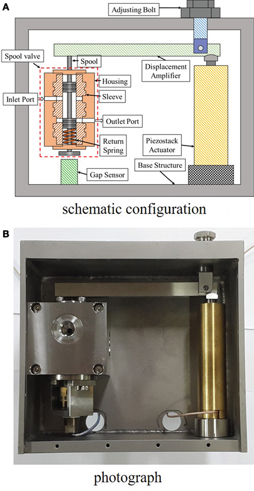
Figure 1. Schematic configuration and photograph of servo valve system. (A) Schematic configuration and (B) photograph.
Figure 2 shows the schematic diagram of PDDV mechanical model, which is consisted of the piezostack, lever-hinge, and spool valve. The dynamic equations of the piezostack actuator and the spool can be obtained as follows:
where xp and xs are the displacement of the piezostack and spool. Vp, mp, cp, and kp are the input voltage to the piezostack, the mass, damping coefficient, and stiffness of the piezostack, and ms, cs, and ks are the mass, damping coefficient, and stiffness of the spool, respectively. d33 is the charge constant of the piezostack. Fp is the acting force from a piezostack, and Fs is the transmitted force from the displacement magnification device can be obtained as follows:
where dr(=L2/L1) is the amplification ratio of the lever-hinge system. IL and are the mass moment of inertia and the approximated angular acceleration of the lever. Ff is a steady flow force calculated by
where ΔP is the pressure drop and Cd value is selected from 0.6 to 0.65 and it is a function of Reynolds number and cavitation number (Han et al., 2015). θ is the jet angle and A0 is the open area of outlet port calculated by , where Ds and Hs are the diameter of the spool and the height of the outlet port. Finally, the dynamic equation of proposed PDDV system can be expressed as follows:
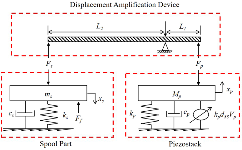
Figure 2. Schematic configuration of mathematical model.
In this study, the positive and normal closed spool valve is considered. The flow rate can be controlled by effective open area. Consequently, flow rate (QS) can be expressed as follows:
where ρ is a density of hydraulic oil. In this work, VG 46 is used for actuating fluid and ρ of VG 46 is 879 kg/m3. The commercial piezostack actuator (pst150/20/80/V25, PIEZOMECHANIK) is considered to control the valve system, and guaranteed working temperature is 80°C because of PZT type piezoelectric material. The displacement from piezostack is magnified by lever-hinge amplifier whose amplification ratio is 21. The mechanical and dimensional properties of the valve system are shown in Tables 1 and 2. The valve system is designed in which the maximum operating frequency of the PDDV is chosen up to 50 Hz. The frequency response of the valve is experimentally obtained by the sinusoidal sweep test. Figure 3 shows the frequency response results obtained from simulation and experiment, respectively.
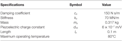
Table 1. Mechanical and dimensional properties of the piezostack actuator.
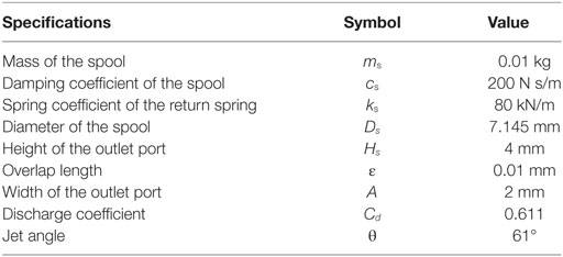
Table 2. Mechanical properties and dimensions of the spool-sleeve.
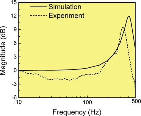
Figure 3. Frequency responses of the PDDV system.
Experimental Apparatus and Results
In order to test the performance of the proposed valve system with high temperature conditions, an apparatus is set up in the large size of the heat chamber. Figure 4 shows the schematic configuration of experimental flow chart to undertake the test. A heat chamber (BK-HTDO-8100, Bookwang C&C co., Ltd.) is used for control the environment temperature and can regulate the temperature from room temperature to 300°C. First, the computer generates low input signal and the generated signal is transferred to voltage amplifier (EC750SA, NF Corporation) through D/A converter (DS1104 R&D Controller Board, dSPACE). The voltage amplifier can magnify the voltage up to 200 V to be applied to the piezostack. The displacement amplifier can generate spool position from the displacement of piezostack. The gap sensor (KD-2306 2SMT, KAMAN) can detect the spool, and the position signal is transferred into the computer through A/D converter (DS1104 R&D Controller Board, dSPACE). Second, nitrogen pressure vessel is used to make the input pressure, and the pressure can be changed to hydraulic pressure by pneumatic-hydraulic cylinder. The cylinder has two rooms and the rooms are separated by the moving piston. The cylinder has 1 l of hydraulic volume, and three cylinders are used for this research. The outlet port of the cylinder is connected to the inlet port of the valve system through inlet pressure sensor (210-40-011-04, Paine Electronics, LLC). The outlet port of the valve is connected to another pressure sensor and flow meter (FT-08AEYB-LEA-3), and the passed fluid goes to the reservoir tank. The sensor signals are saved by the computer using A/D convertor. After the experiment, the cylinders are filled with fluid again using a pump and a valve. All of the sensors, three pneumatic-hydraulic cylinders, and piezostack actuator are in the heat chamber. Furthermore, the valve system is surrounded by aerogel, which is a heat insulator. Figure 5 shows the photograph of established experimental apparatus.
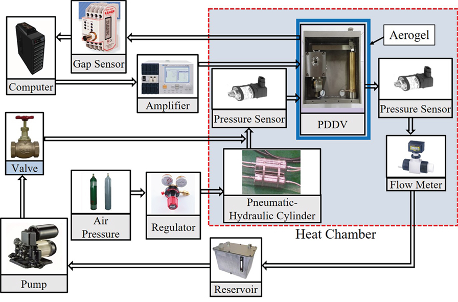
Figure 4. Configuration of experimental apparatus for the tracking control.
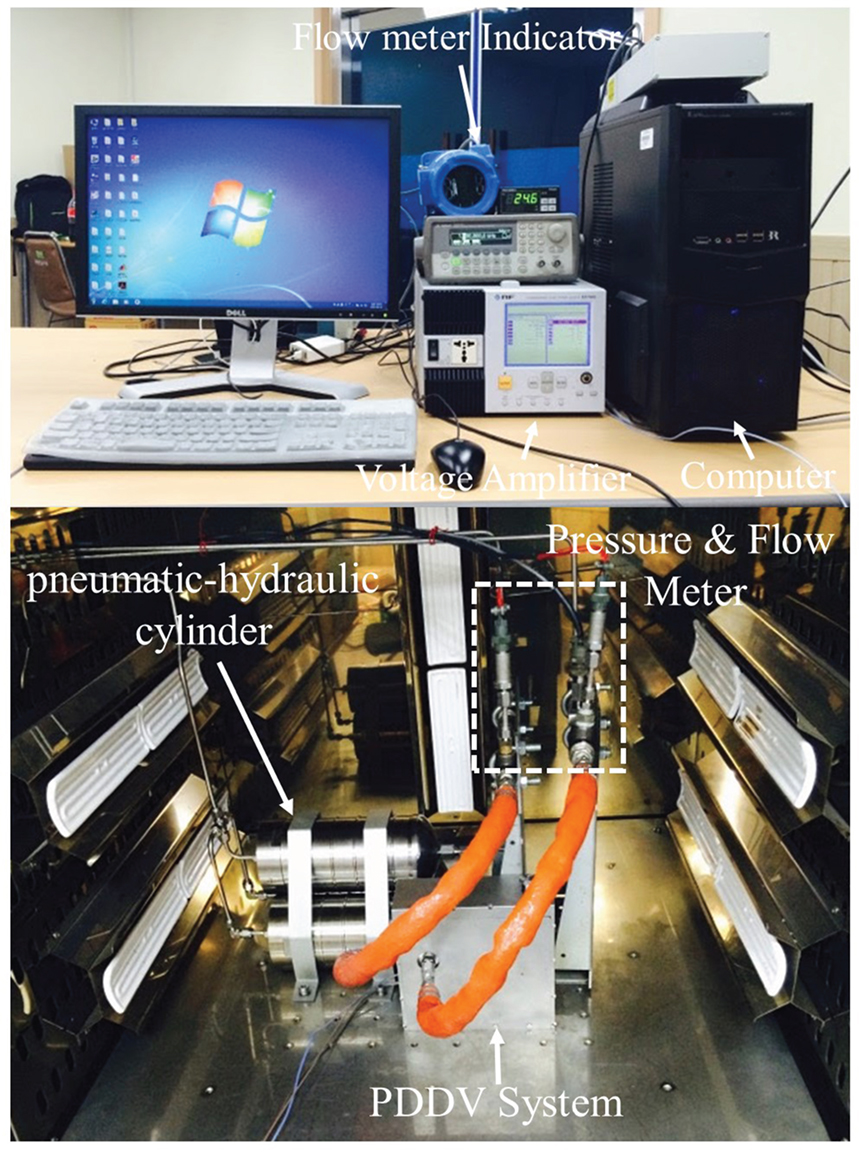
Figure 5. Photo of the setup of the experiments.
In this work, the PZP type of piezostack, guaranteeing its performance at the temperature up to 80, is used. Therefore, the temperature effects on the valve system are firstly investigated in terms of the spool displacement. It is well known that the blocking force of the piezostack actuator is dramatically decreased as the temperature increases (Choi et al., 1999). Figure 6 shows the driving voltage required to reach 0.3 mm of the spool displacement. The PID controller is used for displacement control of spool, and the gain of P, I, and D are chosen by the trial and error method. As shown in the figure, the 90 V is applied to the piezostack at room temperature. However, 150 V is required to get 0.3 mm of the spool displacement at 120°C environment. Therefore, the heat insulator should be used around the piezostack actuator to achieve up to 150°C as shown in the Figure 7. The flow rate according to displacement of the spool is measured by the flow meter shown in Figure 8. Figure 8A shows the result of the flow rate at excitation frequency of 1 Hz. The flow rate data under 3.78 LPM have some errors because the flow meter can detect only the range from 3.78 to 37.8 LPM. In spite of the errors, the flow rate data fairly follows the displacement of the spool as seen. It is seen from Figure 8B that the flow rate data has relatively large error and phase delay because the flow meter has slow response time. Therefore, in this work, control target is selected as the displacement of the spool instead of the flow rate to accommodate high excitation frequency. It is remarked that the response time of the displacement sensor is sufficiently fast to acquire the signal occurred at the excitation frequency of 200 Hz.
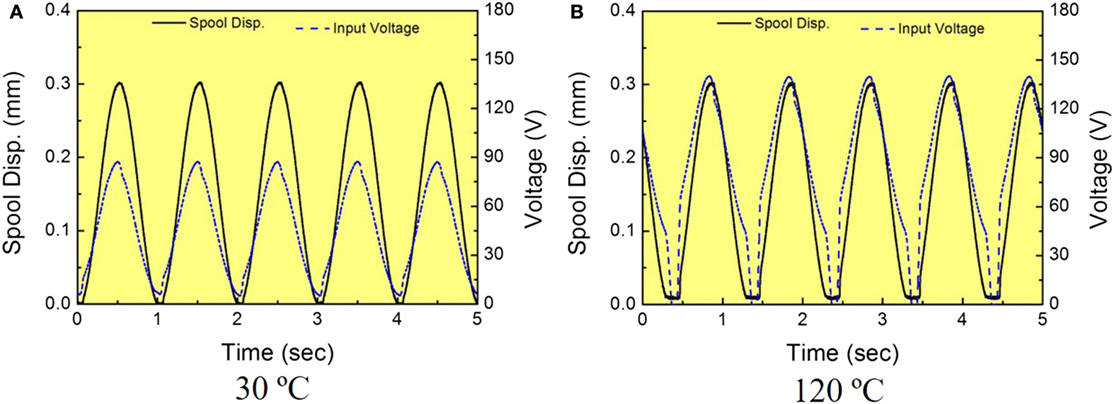
Figure 6. Spool displacement and input voltage at two different temperatures. (A) 30°C and (B) 120°C.
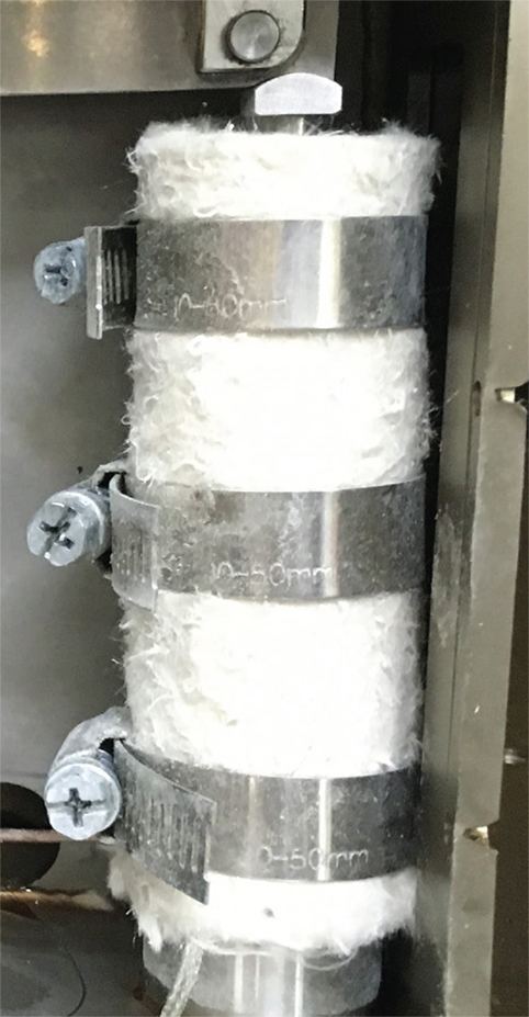
Figure 7. Photograph of the piezostack actuator with the heat insulation.
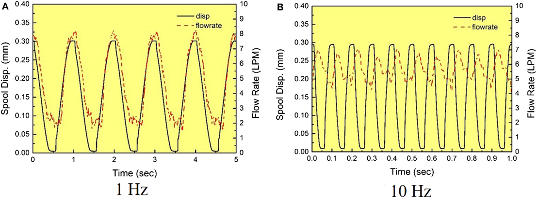
Figure 8. Flow rate measured by the flow meter. (A) 1 Hz and (B) 10 Hz.
As mentioned earlier, in this work, a simple PID feedback controller is adopted to achieve tracking control response of the spool displacement. As well known, the PID control input is calculated as flows:
where e(t) is the error of displacement of the spool between desired and actual signals. kp, ki, and kd are the proportional, integral, and derivative gain of PID controller, respectively. The kp, ki, and kd are determined using Ziegler–Nichols tuning method with each temperature condition. Figure 9 shows the tracking control results of the spool displacement at 1 Hz. At low temperature with 0.12, 80, and 0.0001 of kp, ki, and kd gains, the maximum input voltage is 80 V to reach the 0.3 mm with a small error. The maximum voltage is 119 V at 150°C with 0.2, 80, and 0.0001, and tracking error is almost the same as room temperature. The maximum flow rate is 9.077 LPM and 11.734 LPM at low temperature and 150°C. However, the minimum flow rate has a big error because the flow meter has 3.78–37.8 LPM measurement range. In high temperature, the maximum flow rate increases since the viscosity of the hydraulic oil decreases. Figure 10 shows the experimental results, which are operated at 200 Hz with room temperature and 150°C. The PID gains are changed from 0.12 and 620 to 0.25 and 420 at room temperature and high temperature, respectively. The phase (time) delay is occurred as expected, and the delay is more serious at 200 Hz frequency. The phase delay of 75.6° is occurred at room temperature, while it is 79.2° at 150°C. Because the value of the phase delay is less than 180°, the system is still stable with a certain margin. The tracking error caused by time delay is observed, and the delay is identified by 1 ms in both cases. The dominant reason makes the time delay that the stiffness of the return spring is not enough to operate up to 200 Hz without delay. Therefore, the stiffness will be designed much higher for the valve system in the next study. However, the time delay is not directly related to the operating temperature. The used simple PID controller has good performance with fixed conditions such as 150°C and 200 Hz, but the control performance loses when the operating condition is changed from the initial condition to different conditions, such as operating temperature and frequency. Therefore, a fuzzy algorithm is applied for tuning the gain of ki because the ki is changed frequently with temperature and operating frequency. The fuzzy rule is based on the acquired gains by the experiment. Figure 11 shows the membership function of temperature input variable, frequency input variable, and output variable of ki. The membership function of output variable is constructed based on ki from the results of Ziegler–Nichols tuning method. Table 3 shows the rule base table of two input and one output variables. The center of gravity defuzzification method is used to define output value (Lilly, 2011). Figure 12 presents the tracking result obtained from the fuzzy associated with PID controller. In this experimental, the operating temperature is regulated by 110°C. Figures 12A,B show the tracking result at the excitation frequency of 50 and 200 Hz, respectively. It is clearly observed from the figure that the tracking control results have the time delay as that occurred with the PID controller. However, the spool displacement flows well with the time delay. It is noted that the shape of the spool displacement is distorted because the PID gain is not optimized from the fuzzy algorithm. The choice of the optimized control gains using the fuzzy algorithm will be undertaken in the future.
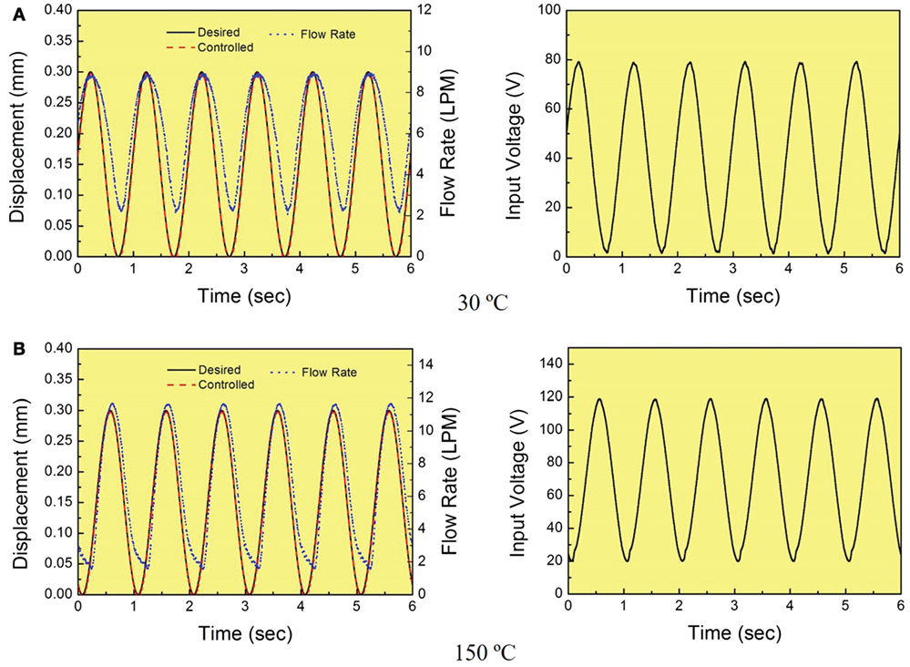
Figure 9. Tracking control results at 1 Hz. (A) 30°C and (B) 150°C.
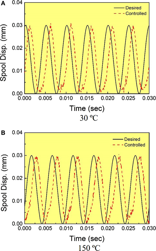
Figure 10. Tracking control results at 200 Hz. (A) 30°C and (B) 150°C.
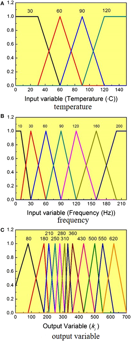
Figure 11. Membership functions. (A) Temperature, (B) frequency, and (C) output variable.
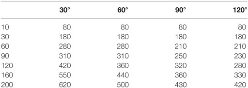
Table 3. Rule base table.
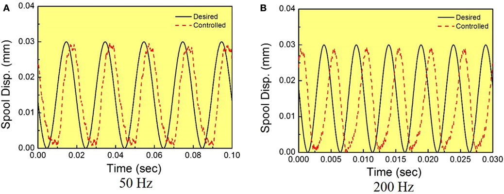
Figure 12. Tracking control results with the fuzzy algorithm at 110°C. (A) 50 Hz and (B) 200 Hz.
Conclusion
In this work, the piezostack direct drive valve (PDDV) system was designed for flow rate control, and control performances were experimentally evaluated at various temperatures. As the first step, the valve system was devised, and operating principle was explained in details. The valve system had been installed into the large heat chamber, which has the electric circuits and various sensors. To change air pressure to the hydraulic pressure, the pneumatic-hydraulic cylinder was used with air pressure vessel. Second, the performance of the valve system was tested without thermal insulation in high temperature. Finally, the performance of tracking control of the spool displacement was evaluated by implementing PID controller, and the fuzzy algorithm integrated PID controller. The tests were undertaken by changing both the operating temperature and excitation frequency. It had been shown that the proposed valve system exhibited good tracking control performances at both 30 and 150°C. However, the time delay was occurred over 50 Hz frequency independently of the operating temperature since the return spring had low stiffness. The results presented in this work are self-explanatory, justifying that the piezostack actuator can be effectively employed for active servo valve system to control fast flow rate at high temperatures. It is finally remarked that the thermal insulation is required to operate the piezoactuator-driven valve system at high temperature up to 150°C, and control durability of the servo valve system should be undertaken at high temperatures for practical utilization.
Author Contributions
S-BC developed the concept of the proposed valve system and CH and Y-HH did experimental testing.
Conflict of Interest Statement
The authors declare that the research was conducted in the absence of any commercial or financial relationships that could be construed as a potential conflict of interest.
References
Ahn, B. I., and Jeon, D. Y. (2002). A study on the vibration reduction of a driver seat controlling an MR fluid damper. J. Control Autom. Syst. Eng. 8, 861–866. doi: 10.5302/J.ICROS.2002.8.10.861
Choi, S. B., Choi, J. H., Nam, M. H., Cheng, C. C., and Lee, H. G. (1999). A semi-active suspension using ER fluids for a commercial vehicle seat. J. Intell. Mater. Syst. Struct. 9, 601–606. doi:10.1177/1045389X9800900803
Choi, S.-B., and Han, Y.-M. (2010). Piezoelectric Actuators: Control Applications of Smart Materials. New York: CRC Press.
Han, C., Jeon, J., Chung, J. U., and Choi, S. B. (2015). Dynamic characteristics and control capability of a piezostack actuator at high temperatures: experimental investigation. Smart Mater. Struct. 24, 11. doi:10.1088/0964-1726/24/5/057002
Jeon, J., Han, C. H., Chung, J. U., and Choi, S. B. (2015). Performance evaluation of a piezoactuator-based single-stage valve system subjected to high temperature. Smart Mater. Struct. 24, 11.
Jeon, J., Nguyen, Q. H., Han, Y. M., and Choi, S. B. (2013). Design and evaluation of a direct drive valve actuated by piezostack actuator. Adv. Mech. Eng. 5, 12.
Li, S., and Song, Y. (2007). Dynamic response of a hydraulic servo-valve torque motor with magnetic fluids. Mechatronics 17, 442–447. doi:10.1016/j.mechatronics.2007.04.011
Li, Y. W., Zhou, X. L., and Li, F. X. (2010). Temperature-dependent mechanical depolarization of ferroelectric ceramics. J. Phys. D Appl. Phys. 43, 1–8.
Niezrecki, C., Brei, D., Balakrishnan, S., and Moskalik, A. (2001). Piezoelectric actuation: state of the art. Shock Vib. Digest 33, 269–280. doi:10.1177/058310240103300401
Paul, A. K., Mishra, J. K., and Radke, M. G. (1994). Reduced order sliding mode control for pneumatic actuator. IEEE Trans. Control Syst. Technol. 2, 271–276. doi:10.1109/87.317984
Proch, D., and Trickl, T. (1989). A high-intensity multi-purpose piezoelectric pulsed molecular beam source. Rev. Sci. Instrum. 60, 713–716. doi:10.1063/1.1141006
Keywords: piezoelectric, servo systems, tracking control, temperature, flow rate
Citation: Han C, Hwang Y-H and Choi S-B (2017) Tracking Control of a Spool Displacement in a Direct Piezoactuator-Driven Servo Valve System. Front. Mater. 4:9. doi: 10.3389/fmats.2017.00009
Received: 05 November 2016; Accepted: 13 March 2017;
Published: 29 March 2017
Edited by:
Ilkwon Oh, KAIST, South KoreaReviewed by:
Xiaomin Dong, Chongqing University, ChinaHuaxia Deng, Hefei University of Technology, China
Xing Shen, Nanjing University of Aeronautics and Astronautics, China
Copyright: © 2017 Han, Hwang and Choi. This is an open-access article distributed under the terms of the Creative Commons Attribution License (CC BY). The use, distribution or reproduction in other forums is permitted, provided the original author(s) or licensor are credited and that the original publication in this journal is cited, in accordance with accepted academic practice. No use, distribution or reproduction is permitted which does not comply with these terms.
*Correspondence: Seung-Bok Choi, c2V1bmdib2tAaW5oYS5hYy5rcg==