- Sullivan Park, Corning Incorporated, Corning, NY, USA
The indentation deformation and cracking responses of ion-exchanged glasses were measured using quasi-static and dynamic loading cycles. Two glass types were compared, a normal glass that deforms to a large extent by a shearing mechanism and a damage-resistant glass that comparatively deforms with less shear and more densification. The quasi-static indentation cracking threshold for median/radial cracks for the ion-exchanged normal glass was determined to be 7 kgf, while the ion-exchanged damage-resistant glass required loads exceeding 30 kgf. The increased cracking threshold of the damage-resistant glass composition is attributed to the deformation mechanism, i.e., deformation with greater densification/less shear results in less subsurface damage and less residual stress. Both glass types were also subjected to dynamic indentation where the contact event time was more than 10,000 times shorter than the quasi-static condition. Under dynamic loading conditions, the cracking thresholds of the ion-exchanged normal and damage-resistant glasses increased to greater than 50 kgf and greater than 150 kgf, respectively. The stress-induced optical retardation was compared for quasi-static and dynamic indents made at sub-cracking threshold loads for both glasses. For indents made at the same sub-cracking threshold load in the normal glass, optical retardation mapping indicates less residual stress surrounding dynamic indents when compared to quasi-static indents. This suggests a rate dependence on the deformation mechanism in normal glasses with higher rates promoting densification in favor of shear. However, for damage-resistant glass, the stress-induced optical retardation is the same for indents made at both quasi-static and dynamic indentation rates.
Introduction
Vickers indentation is a valuable tool for comparing the sharp contact cracking resistance of glasses. Sharp contact is defined by the response of the glass, where a local contact exceeds the elastic limit and results in a permanent impression in the glass surface. Sharp contact is the primary failure mode in ion-exchanged cover glass (Price et al., 2009). Failure occurs during drops onto irregular, hard surfaces that generate large median/radial cracks originating in the subsurface of a sharp contact impression that penetrate the depth of compressive layer (DOL) and enter the central tension (CT) region. Crack extension through the depth of layer typically occurs with minimal assistance from bend induced stresses since most devices utilize a design that keeps the cover glass fairly rigid. The Vickers indentation cracking test is used to measure the resistance to the formation of large median/radial cracks under controlled/repeatable testing conditions in a rigid configuration and closely replicates the failure mechanism seen in cover glass in the field (Price et al., 2009).
The dependence of indentation cracking threshold on glass structure and related deformation mechanisms in non-strengthened glasses is relatively well understood. Non-bridging oxygen (NBO) content in glasses is closely related to the competing shear and densification deformation mechanisms (Peter, 1970; Ernsberger, 1977). Normal glasses contain an abundance of NBOs and tend to deform with more volume conserving shear deformation that ultimately creates subsurface shear faulting damage as indentation load increases (Hagan and Swain, 1978; Arora et al., 1979; Hagan, 1980; Hagan and Van Der Zwaag, 1984). This mechanism has been described as a preferential deformation along pathways through ionically bonded modifier-rich interfaces between anions, or along modifiers associated with NBOs (Peter, 1970; Ernsberger, 1977). Glasses with high NBO content also tend to have higher packing densities which favor shear deformation by reducing the free volume that can accommodate the competing densification mechanism (Mackenzie, 1963; Ernsberger, 1968; Neely and Mackenzie, 1968; Yoshida et al., 2005; Greaves et al., 2011; Rouxel, 2014). Shear deformation during indentation leads to high residual stresses (Yoffe, 1982) and extensive subsurface damage (Hagan and Swain, 1978; Arora et al., 1979; Hagan, 1980; Hagan and Van Der Zwaag, 1984; Gross, 2012), thus the load required to form strength limiting median/radial cracks is relatively low. Glasses with limited NBO contents tend to deform with more volume reducing densification (Mackenzie, 1963; Neely and Mackenzie, 1968). For resistance to strength limiting flaw formation, i.e., resistance to the formation of median and/or radial cracks during indentation, densification is the preferred deformation mechanism since it creates less subsurface damage (Hagan, 1979; Gross, 2012) and less residual stress to drive extension of the strength limiting flaws (Yoffe, 1982). Densification necessarily requires free volume and has been described as an interlocking or entanglement of portions of the network, when elastic compression is accompanied by shear deformation (Mackenzie, 1963; Neely and Mackenzie, 1968). When comparing a glass with many NBOs like soda-lime to a glass with few NBOs like silica, the glass with few NBOs has more free volume and this contributes greatly to its ability to densify. However, since some degree of shear aids in the densification process, the substitution of a low coordination number glass former like trigonal boron oxide in the place of tetrahedral silica has been shown to increase the crack resistance (Kato et al., 2010) despite increasing the packing density (Gross, 2017). For a glass with limited NBOs, reducing the average number of constraints on the network forming cations apparently aids in the densification process even as free volume is reduced (Gross, 2017). Incorporation of trigonal boron also introduces another densification mechanism, the conversion of trigonal units to tetrahedral units under pressure (Grimsditch et al., 1996; Du et al., 2004; Wu et al., 2009). Glasses that deform primarily by densification such as silica are typically referred to as anomalous. These anomalous glasses produce high radial tensile stresses at the surface at the contact boundary of a Vickers indenter during application of the load, so readily form ring cracks originating at the surface if any surface flaws are present (Yoffe, 1982; Gross, 2012). The ability to deform with some amount of shear also reduces the driving force for ring cracking seen in anomalous glasses like silica (Yoffe, 1982; Gross, 2012). The damage-resistant glasses studied presently have a higher tendency toward densification than normal glasses, yet do not form ring cracks during indentation.
The compositional levers used to enhance crack resistance in non-strengthened glasses can be incorporated into ion-exchangeable glasses to provide additional crack resistance above that provided by ion-exchange alone. If the deformation zone is contained under net compression due to the ion-exchange profile, the resistance to the formation of flaws oriented perpendicular to the surface is increased by preventing the extension of subsurface damage into strength limiting median/radial cracks. If the tendency toward indentation-induced subsurface damage is reduced through compositional design and is coupled with the resistance of large flaw formation from ion-exchange, the crack resistance is greatly enhanced as shown in this work. Since the free volume beneath the indent impression is a key driver for the deformation mechanism, the compressive stress (CS) profile or degree of “ion stuffing” as a function of depth can play a significant role on the amount of densification obtained. For this study, glass types are compared with similar stress profiles to reduce the effect of this variable.
While quasi-static Vickers indentation can be used the mimic the sharp contact damage created by drop events in the field, the duration of this test is far longer than a real world sharp contact event. Dynamic indentation is used in this study to move closer to the rate of an actual drop event and to study changes to the deformation mechanisms and crack resistances of normal and damage-resistant glass types.
Materials and Methods
Two glass compositions were obtained for this study, a normal glass (Dejneka and Gomez, 2014) and a damage-resistant glass (Barefoot et al., 2013). The normal glass was an alkali aluminosilicate having %R2O/%Al2O3 = 1.57, where R2O is the sum of alkali oxides and %RxO/%Al2O3 = 2.1, where RxO is the sum of alkali and alkaline earth oxides (all percentages given are in mole). The damage-resistant glass was an alkali boroaluminosilicate having %R2O/%Al2O3 = 1.04 and was free of alkaline earth oxides. The normal glass had less than 1 mol% B2O3 as compared to 7 mol% B2O3 for the damage-resistant glass. The glasses were prepared by an overflow, down draw process to a thickness of 1.3 mm. The normal and damage-resistant glasses each had an as-formed fictive temperature of approximately 700°C. Sheets of glass were scribed and broken into 50 mm × 50 mm test coupons. Ion-exchanged parts were prepared by immersing in a refined molten KNO3 bath at 410°C for 8 h. Following ion-exchange, the normal glass had a surface CS of 815 MPa with a DOL of 55 µm and the damage-resistant glass had a CS of 715 MPa with DOL of 55 µm. The surface CS and DOL were measured for normal and damage-resistant glasses using an Orihara FSM-6000LE surface stress meter. The stress optical coefficient and refractive index used for stress meter measurements for the normal glass were 2.940 nm/mm/MPa and 1.50, respectively. For the damage-resistant glass, a stress optical coefficient of 3.470 nm/mm/MPa and a refractive index of 1.49 were used. The stress optical coefficients were determined using a diametral compression fixture and Olympus BX53 polarized light microscope. The refractive indices were determined using a Bausch and Lomb precision refractometer at 589.3 nm. The stress profiles followed a complementary error function as expected. The CT values were estimated to be 45 and 40 MPa for normal and damage-resistant glass, respectively, by the following equation:
Samples of the normal glass were also prepared from crushed fusion glass that was remelted in a covered platinum crucible for 12 h at 1,650°C. The glass was poured from the crucible onto a clean and smooth stainless steel table then annealed at 625°C for 12 h and furnace cooled to room temperature. The glass was then finished to produce 15 mm × 50 mm × 50 mm specimens with six-sided optical polish. Specimens were ion-exchanged at 410°C for 8 h in refined molten KNO3 to obtain low enough CT versions of the normal glass so that any crack systems formed during indentation studies would be arrested in the bulk rather than driven to failure by the stored tensile stress. The CS was 1,012 MPa, the DOL was 41 µm, and CT was approximately 3 MPa. These values were determined by the same methods described above.
Cross-sections through Vickers indents made at 0.5 kgf in the non-strengthened normal and damage-resistant glasses at 1.3 mm thickness were prepared using the technique developed by Hagan (1979, 1980). In this technique, indents are made out in front of a crack tip with one of the indent major diagonals aligned with the crack. During unloading the crack extends through the aligned major diagonal and the cross-section containing subsurface deformation can be viewed by optical microscope following extension of the crack to failure by bending.
Quasi-static Vickers indentation was performed on 1.3-mm-thick samples of non-ion-exchanged and ion-exchanged glasses using an Instron with the appropriate load cell (1, 10, or 100 kgf) for the indentation load applied. The indentation load was applied and removed by displacement control at 0.2 mm/min with the maximum load held for 10 s. All indentation work was performed at 25°C in 50% relative humidity. The Vickers crack initiation threshold is defined in this work as the indentation load that produces any number of median/radial cracks in greater than 50% of the indents made at a given load.
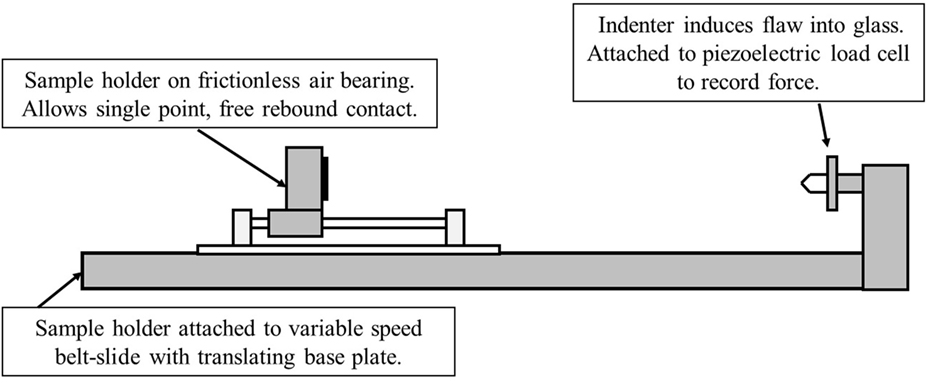
Dynamic Vickers indentation of ion-exchanged samples at 1.3 mm thickness was performed using the test configuration shown in the schematic in Figure 1. Glass samples were rigidly supported in a sample holder and propelled toward the indenter using a Parker belt slide (serial number 1668306801A) to make a normal impact in the center of the glass coupon. The glass and sample holder freely rebound on air bearings following impact to ensure a single contact event. The indenter was connected to a PCB piezoelectric load cell (serial number 261A01) to record impact load as a function of time for the impact event. The load cell collected data at 5,000 Hz to capture the entire contact event. The velocity was controlled using the belt slide and a given velocity produced a nearly constant maximum indentation load. The velocity was directly measured using Vernier VPG-BTD photo-gates. The indentation cracking threshold for dynamic indentation is defined as the velocity and corresponding peak load that produces strength limiting cracks in greater than 50% of tests. During testing, a fresh sample was used for each indentation event.
For each glass type, indents were made in ion-exchanged glass coupons at 1.3 mm thickness at a load that did not produce any radial/median cracks for either quasi-static or dynamic indentation to compare the sizes of the indents and to measure the resulting stress-induced retardation using a Nikon Optiphot2-Pol-polarized light microscope.
Dynamic indentation was also performed on the ion-exchanged normal glass at 15 mm thickness at velocity and load combinations that produced strength limiting cracks in order to observe the type of cracking system produced through a polished edge.
Dynamic indentation of ion-exchanged normal glass coupons at 1.3 mm thickness with a wide angle 170° four-sided pyramidal tip (for reference the Vickers tip has an angle of 136°) was compared to a quasi-static indentation using the same load of 7.99 kgf. The wide angle tip was selected to make observations of an impression that did not contain cracking damage as occurs with sharper tips such as the Vickers.
Results
The surface and cross-sectional views of 0.5 kgf Vickers indents made in the non-ion-exchanged normal glass composition are shown in Figures 2A,B, respectively. The surface view shows a characteristic indent made at 0.5 kgf with associated median/radial cracks. The Vickers crack initiation threshold for the non-ion-exchanged normal glass was determined to be 0.2–0.3 kgf. The cross-sectional view shows the presence of subsurface shear faults with larger crack systems that have initiated from this subsurface damage. The surface and cross-sectional views of the 0.5 kgf Vickers indents made in the non-ion-exchanged damage-resistant glass are shown in Figures 3A,B, respectively. The surface view shows an indent impression without any median/radial cracks. The Vickers crack initiation threshold for the non-ion-exchanged damage-resistant glass was determined to be 1.1–1.2 kgf. The cross-sectional view shows that deformation occurred without formation of subsurface shear faults.
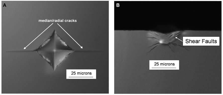
Figure 2. (A) Surface view and (B) cross-section view of quasi-static 0.5 kgf Vickers indents in the non-ion-exchanged, normal glass.
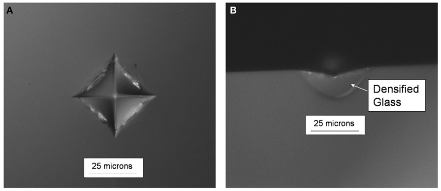
Figure 3. (A) Surface view and (B) cross-section view of quasi-static 0.5 kgf Vickers indents in the non-ion-exchanged, damage-resistant glass.
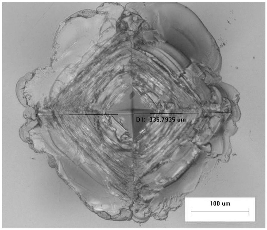
The Vickers indentation cracking threshold for the ion-exchanged normal glass was determined to be 6–7 kgf. Figure 4A shows an image of a characteristic indent with median/radial cracks made at 7 kgf in the ion-exchanged normal glass. For comparison, Figure 4B shows that a 7 kgf indent made in the ion-exchanged damage-resistant glass does not produce median/radial cracks. Figure 5 shows that even at 30 kgf, median/radial cracks do not form in ion-exchanged damage-resistant glass. The width of the 30 kgf indent impression is ~336 μm, so the depth of the indenter was approximately 48 µm (~1/7 of the indent impression width based on indenter geometry) at the maximum load assuming minimal elastic recovery at the impression corners. At maximum load, the indenter was nearly as deep as the 55 µm compressive depth of layer, while the subsurface deformation beneath the impression extended to a depth beyond the compressive depth of layer. The Vickers crack initiation threshold was determined to be 35–40 kgf for the ion-exchanged damage-resistant glass composition. At the median/radial cracking threshold, the damage extends into the CT region of the glass, so the part fails by separating into multiple pieces.
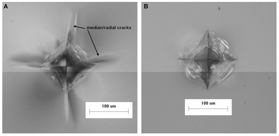
Figure 4. Quasi-static Vickers indents made at 7 kgf in ion-exchanged (A) normal and (B) damage-resistant glasses.
The Dynamic indentation results for the ion-exchanged normal glass are shown in Figure 6. In the plot, the filled symbols indicate specimens that survived the impact event, meaning they did not form median/radial cracks. The maximum indentation load of the load/unload cycle for the surviving parts (filled symbols) is approximately linearly related to the impact velocity. The open symbols represent specimens that failed during the test by the formation of strength limiting cracks that entered the CT region and caused specimen failure by separating into multiple pieces. The failures occurred on the loading half cycle, so typically did not reach the maximum indentation load achieved for survivors at a given impact velocity. The loads required to initiate median/radial cracks in the ion-exchanged normal glass are much higher for dynamic indentation when compared to quasi-static indentation. For example, 50% of indents survive at an impact velocity of 410 mm/s, and those survivors reach indentation loads of ~60 kgf. Figure 7 shows the dynamic indentation results for the ion-exchanged damage-resistant glass. The thresholds for indentation also increase for the dynamic indents when compared to quasi-static indentation. Again, failures occur on the loading half cycle. At ~1,000 mm/s, greater than 50% of the indents survive and reach indentation loads exceeding 150 kgf. At ~1,200 mm/s, four indents survive at loads exceeding 200 kgf. Figure 8 shows an overlay of the load vs. time curves for damage-resistant glasses impacted at 1,000 mm/s. The solid line shows the load vs. time data for a surviving specimen and shows the full curve and peak stress for this velocity. The dashed line shows the load vs. time data for a specimen that failed and indicates that the failure occurred on the loading half cycle. Figure 9 shows an indent made at 213 kgf in the ion-exchanged damage-resistant glass without formation of median/radial cracks. The contact event time was 507 µs, and the impact velocity was 1,168 mm/s. The average major diagonal length was 829 µm. Again, assuming minimal elastic recovery at the indent corners, the depth of the indenter at the maximum load was 118 µm. For these large indents, the deformation zone beneath the indent impression can extend hundreds of microns in depth. Figure 10 shows this with a cross-section view of the subsurface deformation through a polished edge for an indent made at 170 kgf using an impact velocity of 1,005 mm/s. The contact event time for this indent was 512 µs. To compare the rate dependence of deformation response, sub-cracking threshold indents were produced both by quasi-static and dynamic indentation for each glass type. Sub-cracking threshold loads were used since formation of larger crack systems, i.e., median/radial or lateral cracks, will relieve residual stress. Indentation of the ion-exchanged normal glass was performed at a relatively low load of 4.5 kgf due to its low quasi-static threshold. Figure 11A shows the normal glass indented with the dynamic indenter at 4.5 kgf with a contact event time of 1,266 µs. The horizontal major diagonal length was 116.26 µm. Figure 11B shows the normal glass indented with the quasi-static indenter at 4.5 kgf with a contact event time of 55 s. The contact event time for quasi-static indentation was more than 40,000 times longer than the dynamic indentation. The horizontal major diagonal length of the quasi-static indent was 119.99 µm. Since the ion-exchanged damage-resistant glass has a much higher quasi-static cracking threshold, a higher load of 24.8 kgf was selected to compare contact rates. Figure 11C shows the damage-resistant glass indented at 24.8 kgf with the dynamic indenter with a contact event time of 867 µs. Due to the higher velocity of the higher load indents, the contact time is shorter when compared to the dynamic indent at 4.5 kgf in the normal glass. The horizontal major diagonal length was 292.22 µm. Figure 11D shows the damage-resistant glass indented at 24.8 kgf under quasi-static conditions with a contact event time of 121 s. At higher loads, the quasi-static indentation contact event time is longer since the displacement rate during load and unload is fixed. In this case, the contact event time for quasi-static indentation was more than 100,000 times longer than the dynamic indentation. The horizontal major diagonal length for the quasi-static indent was 306.43 µm. The indentation threshold results for quasi-static and dynamic indentation are summarized in Table 1.
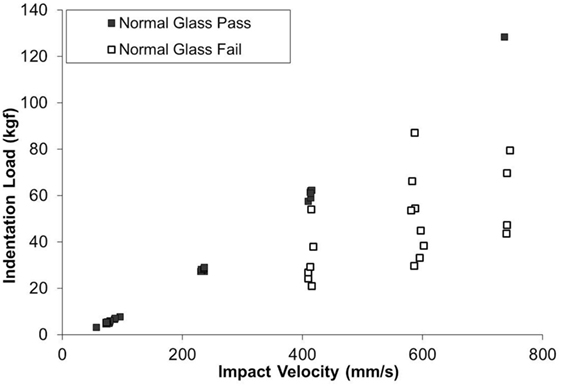
Figure 6. Indentation load vs. impact velocity for dynamic indentation of ion-exchanged normal glass. Filled symbols represent test specimens that did not form strength limiting median/radial cracks. Open symbols represent test specimens that formed strength limiting median/radial cracks and simultaneously failed by separating into multiple pieces.
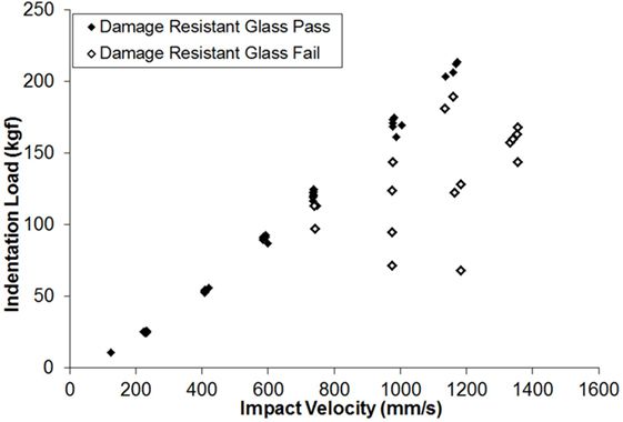
Figure 7. Indentation load vs. impact velocity for dynamic indentation of ion-exchanged damage-resistant glass. Filled symbols represent test specimens that did not form strength limiting median/radial cracks. Open symbols represent test specimens that formed strength limiting median/radial cracks and simultaneously failed by separating into multiple pieces.
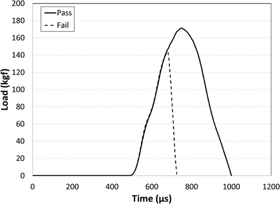
Figure 8. Overlay of dynamic indentation contact event data for damage-resistant glass tested at 1,000 mm/s impact velocity. Part failures occurred during the loading half cycle as indicated by the dashed line, so did not reach the peak load for a given impact velocity. For parts that did not fail (solid line), the contact event time was recorded as the time from initial load to full unload.
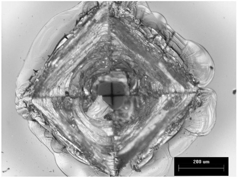
Figure 9. Dynamic indent made in ion-exchanged damage-resistant glass at 213 kgf without formation of median/radial cracks. Major diagonal length is 829 µm. Contact time from initial load to full unload was 507 µs. Impact velocity was 1,168 mm/s.
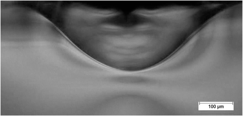
Figure 10. View through a polished edge showing the extent of subsurface deformation for a 170 kgf dynamic Vickers indent in ion-exchanged damage-resistant glass. The impact velocity was 1,005 mm/s and the contact event time was 512 µs.
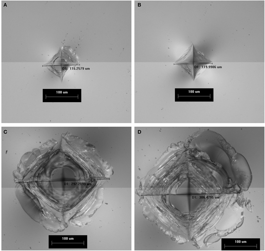
Figure 11. Indents made in ion-exchanged glasses under quasi-static and dynamic loading conditions. (A) Normal glass indented at 4.5 kgf using the dynamic indenter with contact event time of 1,266 µs. (B) Normal glass indented at 4.5 kgf using the quasi-static indenter with contact event time of 55 s. (C) Damage-resistant glass indented at 24.8 kgf using the dynamic indenter with a contact event time of 867 µs. (D) Damage-resistant glass indented at 24.8 kgf using the quasi-static indenter with contact event time of 121 s.
The stress-induced optical retardation is shown for the quasi-static and dynamic indents made at 4.5 kgf in ion-exchanged normal glass in Figures 12A,B, respectively. The 2D grayscale maps and the retardation overlay plot indicate that the retardation is greater in magnitude and spatial extent for the quasi-static indent when compared to the dynamic indent. In the images, bright areas correspond to higher retardation, while dark areas have lower retardation. The small vectors are parallel with the direction of principal tension and indicate a circumferential tension in the region outside of the indent. This stress field promotes median/radial cracking. The vertical dashed lines running though the center of the indents in Figures 12A,B show the locations of the line scans plotted in Figure 12C. The peak retardation (representing the peak stress) is shifted to slightly larger radial locations for the quasi-static indent due to its slightly larger size. On the other hand, Figure 13C shows that retardation is constant along the line scan taken for quasi-static and dynamic indents made at 24.8 kgf in the damage-resistant glass. The locations of the line scans for these indents are indicated by the dashed horizontal lines shown in Figures 13A,B. While no difference is seen in the retardation magnitude, the quasi-static indent is again slightly larger, resulting in the peak retardation (peak stress) being displaced to slightly larger radial locations. The line scans were taken on a line passing through the diagonals for both glass types since median/radial cracks form along this line.
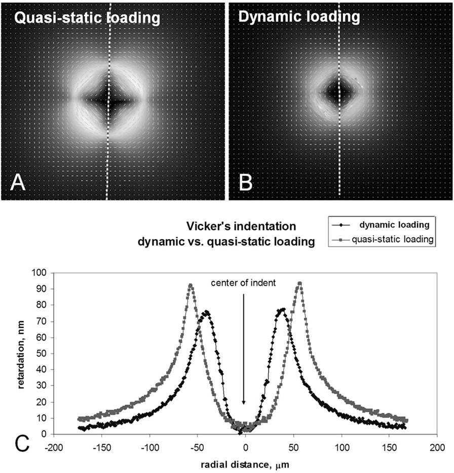
Figure 12. 2D grayscale maps of stress-induced optical retardation of 4.5 kgf indents made in ion-exchanged normal glass. Overlay shows that quasi-static loading on normal glass produces greater stress-induced optical retardation. (A) Quasi-static loading. (B) Dynamic loading. (C) Vicker’s indentation dynamic vs. quasi-static loading.
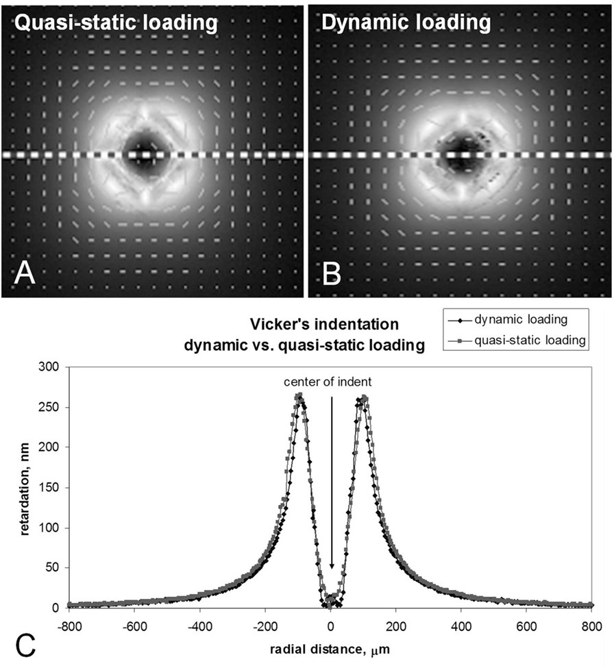
Figure 13. 2D grayscale maps of stress-induced optical retardation of 24.8 kgf indents made in ion-exchanged damage-resistant glass. Overlay shows that quasi-static and dynamic loading produces the same stress-induced optical retardation for damage-resistant glass. (A) Quasi-static loading. (B) Dynamic loading. (C) Vicker’s indentation dynamic vs. quasi-static loading.
Figures 14A,B show indents made at 7.99 kgf in ion-exchanged normal glass with a 170° indenter tip under both quasi-static and dynamic conditions. Due to the wide angle of the indent, cracking damage is absent within the indentation impression. The quasi-static indent impression is noticeably larger and has liquid droplets at the center of the indent. The contact event times were 98 s and 960 µs for the quasi-static and dynamic indents, respectively.
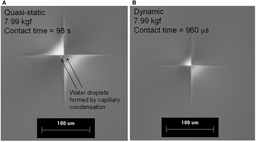
Figure 14. (A) Quasi-static and (B) dynamic indents made in normal glass at 7.99 kgf with 170° indenter tip. Quasi-static indentation is shown to form water droplets at the indent location whereas water is not present for dynamic indentation.
Discussion
The damage-resistant glass composition was demonstrated to have higher resistance to the formation of strength limiting flaws during Vickers indentation for both non-ion-exchanged and ion-exchanged samples using quasi-static indentation. The cross-section of the non-strengthened damage-resistant glass indented at 0.5 kgf shown in Figure 3B exhibits deformation without the formation of subsurface shear cracking damage. Since the damage-resistant glass composition contains only a slight excess of mol% R2O over mol% Al2O3, the glass composition is substantially free of NBOs. As explained earlier, the absence of NBOs has been shown to promote the densification deformation mechanism and suppress shear deformation. The elimination of NBOs increases the free volume as Al is added up to the point of charge balance in alkali aluminosilicates (Ya Livshits et al., 1982). The densification mechanism requires free volume, so the collapse of the network structure through NBO formation and the resulting elimination of free volume will result in a shift of the deformation mechanism toward shear as shown in Figure 2B for the normal glass having excess mol% R2O over mol% Al2O3, i.e., excess NBOs. Since both glass types are formed by a down draw fusion process that is rapidly quenched, the fictive temperatures are considerably higher than if the fictive temperatures corresponded to the glass anneal points. For fusion glass, the fictive temperature is approximately equal to the temperature at a viscosity corresponding to 1,011 P (Dejneka et al., 2012), so the forming process also gives an improvement in free volume for both glass types when compared to annealed glass samples. Both the normal and damage-resistant glasses exhibit normal free volume and density dependence on fictive temperature (Bruckner, 1970), so the higher fictive temperature state has higher free volume and lower density. The damage-resistant glass also has approximately 7 mol% B2O3 and when added to a glass with R2O approximately equal to Al2O3, the boron exists primarily in a trigonal coordination state (Kato et al., 2010; Gross, 2017). The incorporation of trigonal units into the glass structure reduces the average coordination number of glass-forming cations and the increased ease of rearrangement of the connected, low-NBO glass network allows greater ease of densification under a sharp contact. The densification mechanism is believed to require some amount of shear deformation, so it is hypothesized that the trigonal boron allows some shear deformation with reduced tendency toward shear cracking. The surface image in Figure 3A shows apparent shear faulting intersecting the surface adjacent to the impression edges, even though the subsurface image in Figure 3B does not show shear faulting damage. One possible explanation is that fault-free subsurface shear deformation is possible in the lower coordination, low-NBO-containing network under this loading condition in a flaw-free subsurface zone, but as the shear deformation approaches the surface and interacts with surface flaws, near-surface shear cracks are observed. Some amount of trigonal boron units are also expected to convert to tetrahedral boron units under high pressure as a densification mechanism (Grimsditch et al., 1996; Du et al., 2004; Wu et al., 2009).
Following ion-exchange, the quasi-static indentation cracking thresholds for both glass types are significantly higher when compared to the non-ion-exchange values. For the 30 kgf indent in damage-resistant glass shown in Figure 5, the impression depth was approximately 48 µm with the subsurface deformation zone extending beyond the 55 µm DOL and into the region of stored CT. This assumes that the ion-exchange stress profile redistribution as a consequence of indentation was minimal. Thus, if subsurface cracking damage was present as is typical with normal glasses then it would be acted upon by the 40 MPa CT stored within the glass causing median/radial crack extension.
The dynamic indentation results for the normal and damage-resistant glasses show that much higher indentation loads are required to initiate strength limiting flaws when compared to the quasi-static indentation results. The cracking threshold for the damage-resistant glass still remained considerably higher than the normal glass at the dynamic indentation rates. The specimen failures, as given by the open symbols in Figures 7 and 8, occur during the loading half cycle, i.e., the during the segment from the initial load to the highest peak load obtainable for a surviving specimen for a given impact velocity as shown for the example of ion-exchanged damage-resistant glass impacted at 1,000 mm/s in Figure 9. The formation of strength limiting flaws for these two glass types on the loading half cycle is a unique characteristic of dynamic Vickers indentation. Typically, during quasi-static indentation, the formation of observable strength limiting flaws occurs during unloading or after being fully unloaded. This indicates that the strength limiting flaw formation during quasi-static indentation is being driven by residual stress. On the other hand, the formation of strength limiting flaws and simultaneous failure on the loading cycle during dynamic indentation indicates that a large flaw is being generated on the loading cycle and is entering the CT region to extend critically. Two flaw systems are typically considered as having the potential for activation during the loading half cycle, the subsurface penny-shaped median crack and ring/cone cracks (Cook and Pharr, 1990). The standard specimen thickness of 1.3 mm used in this study could not be analyzed by Fractography practices to determine the crack type at the origin due to the high energy of the failures resulting in the ejection of the origin and surrounding area during failure. However, for the ion-exchanged normal glass at 15 mm thickness, the CT was only 3 MPa, low enough that any crack systems formed during indentation would form and be arrested in the bulk. Figure 15 shows an example cross-section of a dynamic indent made at 51.9 kgf in the 15-mm-thick specimen through a polished edge and shows that it is a median crack that forms on the loading cycle and extends 1.43 mm from the surface. Formation of such a flaw in the 1.3-mm-thick specimen would readily lead to specimen failure. None of the dynamic indents made in the 15-mm-thick sample contained ring/cone cracks. As shown in Figure 12, the normal glasses do appear to deform with more densification and less shear at higher rates of contact since the resulting residual stress is lower when compared to quasi-static indentation. However, this apparent increase in densification is not so high as to lead to the formation of the ring and cone cracks that are prevalent in indentation of highly densifiable anomalous glasses such as silica. It should be noted that the CS of the 15-mm sample was higher and the depth of layer shallower when compared to 1.3-mm fusion glass. Since the thick glass required annealing, the ionic interdiffusion was slower during ion-exchange, and the compression was higher than the glass with higher fictive temperature obtained by fusion. CS is also increased for thicker specimens according to force balance considerations.
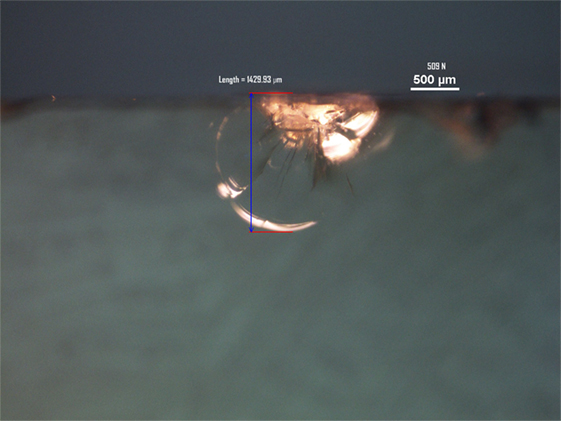
Figure 15. Image of median crack taken through the polished edge of a 15-mm thick ion-exchanged normal glass indented at 509 N (51.9 kgf).
Both normal and damage-resistant glasses show that the indentation size for a given load increases with longer contact times as shown in Figure 11. It has previously been shown that glass hardness or indentation size is dependent on indentation dwell time and is also dependent on the water content of the environment (Hirao and Tomozawa, 1987). Higher indentation dwell times showed lower hardness as the diamond indenter would penetrate deeper into the glass. Hirao and Tomozawa (1987) used Fourier transform infrared spectroscopy to reveal an increase in the water content of the indentation deformation region when water was present in the indentation testing environment. A water-rich deformation region would have a lower local viscosity that is more susceptible to flow or indentation creep. At the high impact rates used in with dynamic indentation, it is expected that the water entry into the glass deformation zone is minimal, thus minimizing any indentation creep. During quasi-static indentation, water from the atmosphere readily condenses in the small radius of curvature region formed between the indenter and the glass surface by a capillary condensation mechanism (Chen and Soh, 2008) and provides the water source for interaction with the deformation zone. Following quasi-static Vickers indentation, the excessive cracking damage within the impression makes observation of residual water within the impression difficult. By using an ultra-wide four-sided 170° indenter, an indent impression can be produced that is free of any cracking damage at the surface. As shown in Figure 14A, droplets of liquid are visible at the center of the indent impression following quasi-static indentation. For dynamic indentation, no such droplets are present. Apparently, capillary condensation between the indenter and glass surface does not occur within the short contact event times associated with dynamic indentation. Due to the wide angle of the indenter, small rate-dependent changes in indentation depth produce relatively large changes in major diagonal length as seen in the images in Figure 14.
Shorter indentation dwell time has also been shown to improve crack resistance (Hirao and Tomozawa, 1987) and is consistent with the observations made in this study. Hirao and Tomozawa (1987) again attributed this observation to the time-dependent water entry into the deformation zone during application of the indentation load. The interaction of water with strained bonds is well known through glass fatigue studies (Charles, 1961; Hillig, 1962; Phillips, 1965; Weiderhorn and Bolz, 1970). One would expect the crack forming sequences including the formation of shear faults and the extension of this shear damage to form median/radial and lateral cracks can be assisted by the breaking up of the glass network through formation of terminal −OH groups. Lawn et al. (1983) also proposed that dwell time-dependent cracking observations were highly dependent on water interaction. They proposed a shear fault model where decohesion distance of the faults depended on time-dependent water diffusion into the shear fault interfaces (Lawn et al., 1983). Kurkjian et al. (1995) also demonstrated that indentation performed at liquid nitrogen temperatures on normal glasses resulted in less shear deformation, and this observation was attributed to the reduction in water activity. All of these studies suggest that the minimization of water interaction would greatly improve crack resistance and the dynamic indentation results presented in this study appear to be another example of this.
A change in deformation mechanism away from shear and toward densification also promotes improved resistance to the formation of strength limiting flaws during indentation by reducing the amount of subsurface damage and lowering the residual stress. When comparing quasi-static and dynamic indents made at 4.5 kgf in normal glass in Figure 12, the stress-induced optical retardation is significantly higher for the quasi-static indent. This indicates a shift in the deformation mechanism toward densification that contributes to the improved crack resistance of normal glass during dynamic indentation. On the other hand, the quasi-static vs. dynamic indentation comparison for damage-resistant glass does not show a change in the stress-induced optical retardation. This suggests that for damage-resistant glasses that already deform by densification during quasi-static indentation, the higher indentation rate does not change the deformation mechanism. For normal glass, the difference in optical retardation would likely increase as the difference in contact event time between quasi-static and dynamic indentation becomes greater.
Conclusion
The indentation deformation and cracking behavior of ion-exchanged normal and damage-resistant glasses is highly dependent on the glass structure. Factors that improve the inherent damage resistance, e.g., reduction in NBOs and incorporation of trigonal boron, also give improved damage resistance following ion-exchange. An unexpected finding was that the formation of strength limiting flaws and simultaneous part failure occurs on the loading half cycle in dynamic Vickers indentation of ion-exchanged glass in a rigidly supported configuration. The flaw type that is generated during specimen failure in the dynamic Vickers indentation test was found to be a median crack that extends to a depth that where it is readily acted upon by the stored CT. The indentation cracking threshold is also highly dependent on the contact event time for both glass types and is consistent with previous work. High rate contact appears to eliminate the capillary condensation of water between the indenter and glass surface, thus removing a source of water that is present during quasi-static indentation. In the case of the normal glass, it also appears that the deformation mechanism shifts away from shear deformation and toward densification for shorter contact event times. This proposed shift in deformation mechanism leads to less subsurface damage and less residual stress, thus contributing to the increased threshold for formation of strength limiting median/radial cracks. Future work will examine the water interaction with the deformation region during indentation of various glass types to better understand the role of water in rate-dependent deformation and cracking.
Author Contributions
This manuscript was written through the contribution of all authors. TG was the primary researcher for this work and primary author for this manuscript; conducted quasi-static and dynamic indentation experiments, scratch experiments, and indentation cross-sectioning experiments. JJ performed polarized light microscope measurements and analysis to compare the optical retardation of quasi-static and dynamic indents.
Conflict of Interest Statement
The authors declare that the research was conducted in the absence of any commercial or financial relationships that could be construed as a potential conflict of interest.
Acknowledgments
Thanks to Scott Glaesemann for discussion of indentation fundamentals. Thanks to Tim Smith, Matt Black, Anthony Furstoss, Don Clark, and Leon Reed for experimental assistance. Thanks to Charlene Smith for manuscript review and useful feedback.
References
Arora, A., Marshall, D. B., Lawn, B. R., and Swain, M. V. (1979). Indentation deformation/fracture of normal and anomalous glasses. J. Non Cryst. Solids 31, 415–428. doi:10.1016/0022-3093(79)90154-6
Barefoot, K. L., Dejneka, M. J., Gomez, S., Gross, T. M., and Shashidhar, N. (2013). Crack and Scratch Resistant Glass and Enclosures Made Therefrom. U.S. Patent No 8,586,492. Washington, DC: U.S. Patent and Trademark Office.
Bruckner, R. (1970). Properties and structure of vitreous silica I. J. Non Cryst. Solids 5, 123–175. doi:10.1016/0022-3093(70)90190-0
Charles, R. J. (1961). “A review of glass strength,” in Progress in Ceramic Science, Vol. 1, ed. J. E. Burke (New York, NY: Pergamon Press), 1–38.
Chen, S. H., and Soh, A. K. (2008). The capillary force in micro- and nano-indentation with different indenter shapes. Int. J. Solids Struct. 45, 3122–3137. doi:10.1016/j.ijsolstr.2008.01.014
Cook, R. F., and Pharr, G. M. (1990). Direct observation and analysis of indentation cracking in glasses and ceramics. J. Am. Ceram. Soc. 73, 787–817.
Dejneka, M. J., Ellison, A. J., and Gomez, S. (2012). Ion-Exchanged, Fast Cooled Glasses. U.S. Patent No 8,232,218. Washington, DC: U.S. Patent and Trademark Office.
Dejneka, M. J., and Gomez, S. (2014). Silicate Glasses Having Low Seed Concentration. U.S. Patent No 8,623,776. Washington, DC: U.S. Patent and Trademark Office.
Du, L. S., Allwardt, J. R., Schmidt, B. C., and Stebbins, J. F. (2004). Pressure-induced structural changes in a borosilicate glass-forming liquid: boron coordination, non-bridging oxygens, and network ordering. J. Non Cryst. Solids 337, 196–200. doi:10.1016/j.jnoncrysol.2004.03.115
Ernsberger, F. M. (1968). Role of densification in deformation of glasses under point loading. J. Am. Ceram. Soc. 51, 545–547.
Greaves, A. L., Greer, A. L., Lakes, R. S., and Rouxel, T. (2011). Poisson’s ratio and modern materials. Nat. Mater. 10, 823–837. doi:10.1038/nmat3134
Grimsditch, M., Polian, A., and Wright, A. C. (1996). Irreversible structural changes in vitreous B2O3 under pressure. Phys. Rev. B Condens. Matter 54, 152–155.
Gross, T. M. (2012). Deformation and cracking behavior of glasses indented with diamond tips of various sharpness. J. Non Cryst. Solids 358, 3445–3452. doi:10.1016/j.jnoncrysol.2012.01.052
Gross, T. M. (2017). “Low modulus, damage resistant glass for ultra-thin applications,” in Flexible Glass for Electronic Applications, ed. S. Garner (New York, NY: Wiley). (in press).
Hagan, J. T. (1979). Cone cracks around Vickers indentations in fused silica glass. J. Mater. Sci. 14, 462–466.
Hagan, J. T. (1980). Shear deformation under pyramidal indentations in soda-lime glass. J. Mater. Sci. 15, 1417–1424.
Hagan, J. T., and Swain, M. V. (1978). The origin of median and lateral cracks around plastic indents in brittle materials. J. Phys. D: Appl. Phys. 11, 2091–2102.
Hagan, J. T., and Van Der Zwaag, S. (1984). Plastic processes in a range of soda-lime silica glasses. J. Non Cryst. Solids 358, 3445–3452.
Hillig, W. B. (1962). “Sources of weakness and the ultimate strength of brittle amorphous solids,” in Modern Aspects of the Vitreous State, ed. J. D. Mackenzie (Washington, DC: Butterfield), 152–194.
Hirao, K., and Tomozawa, M. (1987). Microhardness of SiO2 glass in various environments. J. Am. Ceram. Soc. 70, 497–502.
Kato, Y., Yamazaki, H., Kuro, Y., Yoshida, S., Matsuoka, J., and Akai, T. (2010). Effect of B2O3 content on crack initiation under Vickers indentation test. J. Ceram. Soc. Jpn. 118, 792–798. doi:10.2109/jcersj2.118.792
Kurkjian, C. R., Kammlott, G. W., and Chaudhri, M. M. (1995). Indentation behavior of soda-lime silica glass, fused silica, and single crystal quartz at liquid nitrogen temperature. J. Am. Ceram. Soc. 78, 737–744.
Lawn, B. R., Dabbs, T. P., and Fairbanks, C. J. (1983). Kinetics of shear-activated indentation crack initiation in soda-lime glass. J. Mater. Sci. 18, 2785–2797.
Mackenzie, J. D. (1963). High pressure effects on oxide glasses: I, densification in rigid state. J. Am. Ceram. Soc. 46, 461–476.
Neely, J. E., and Mackenzie, J. D. (1968). Hardness and low-temperature deformation of silica glass. J. Mater. Sci. 3, 603–609.
Peter, K. W. (1970). Densification and flow phenomena of glass in indentation experiments. J. Non Cryst. Solids 5, 103–116.
Price, J. J., Gleasemann, G. S., Clark, D. A., Gross, T. M., and Barefoot, K. L. (2009). 69.3: A mechanics framework for ion-exchanged cover glass with a deep compression layer. SID Symp. Digest Techn. Papers 40, 1049–1051. doi:10.1889/1.3256467
Rouxel, T. (2014). Driving force of indentation cracking in glass: composition, pressure and temperature dependence. Philos. Trans. A 373, 1–26. doi:10.1098/rsta.2014.0140
Weiderhorn, S. M., and Bolz, L. H. (1970). Stress corrosion and static fatigue of glass. J. Am. Ceram. Soc. 53, 543–548.
Wu, J., Deubener, J., Stebbins, J. F., Grygarova, L., Behrens, H., Wondraczek, L., et al. (2009). Structural response of a highly viscous aluminoborosilicate melt to isotropic and anisotropic compressions. J. Chem. Phys. 131, 104504. doi:10.1063/1.3223282
Ya Livshits, V., Tennison, S. B., Gukasyan, S. B., and Kostanyan, A. K. (1982). Acoustic and elastic properties of glass in the Na2O-Al2O3-SiO2 system. Sov. J. Glass Chem. 8, 463–468.
Yoffe, E. H. (1982). Elastic stress fields caused by indenting brittle materials. Phil. Mag. A 46, 617–628.
Keywords: dynamic indentation, damage-resistant glass, densification, shear deformation, ion-exchange
Citation: Gross TM and Price JJ (2017) Vickers Indentation Cracking of Ion-Exchanged Glasses: Quasi-Static vs. Dynamic Contact. Front. Mater. 4:4. doi: 10.3389/fmats.2017.00004
Received: 29 November 2016; Accepted: 07 February 2017;
Published: 22 February 2017
Edited by:
Lothar Wondraczek, University of Jena, GermanyReviewed by:
Satoshi Yoshida, University of Shiga Prefecture, JapanStefan Karlsson, SP Technical Research Institute of Sweden, Sweden
Copyright: © 2017 Gross and Price. This is an open-access article distributed under the terms of the Creative Commons Attribution License (CC BY). The use, distribution or reproduction in other forums is permitted, provided the original author(s) or licensor are credited and that the original publication in this journal is cited, in accordance with accepted academic practice. No use, distribution or reproduction is permitted which does not comply with these terms.
*Correspondence: Timothy M. Gross, Z3Jvc3N0bUBjb3JuaW5nLmNvbQ==
 Timothy M. Gross
 James J. Price
