
95% of researchers rate our articles as excellent or good
Learn more about the work of our research integrity team to safeguard the quality of each article we publish.
Find out more
ORIGINAL RESEARCH article
Front. Mar. Sci. , 24 March 2025
Sec. Ocean Solutions
Volume 12 - 2025 | https://doi.org/10.3389/fmars.2025.1556924
Introduction: Developing wind-wave coupled devices is becoming a research hotspot in offshore renewable energy. While previous studies have primarily concentrated on the hydrodynamic performance of such devices, few have addressed sediment scouring near the foundation, which is critical to their safety.
Methods: Therefore, based on the design of a wind-wave coupled device integrating an offshore fixed wind turbine, a sediment scouring model is developed using the commercial computational fluid dynamics platform Flow-3D®. The numerical model is validated using experimental test data, and the sediment scouring and deposition under the combined effects of waves and currents are investigated.
Results: The results indicate that the oscillating water column tube array can expand the scouring area but have a minor influence on the maximum scouring depth. In addition, due to the sheltered effect of the oscillating water column tubes, the maximum scouring depth near the piles at the far end can be reduced.
Discussion: By optimizing the distance between the tube ends and the seabed, the maximum scouring depth can be reduced by 22.8%, which is beneficial to the safety and stability of the foundation of the coupled device. The key findings of this study provide a more comprehensive design basis for the development and engineering practice of the wind-wave coupled device.
Green and sustainable development has become an irresistible trend globally, and most countries have agreed to develop renewable energy (Yang et al., 2019). There are abundant renewable energies in the ocean, such as wind, wave, and tidal streams, with large reserves and high quality to become a critical part of the future energy mix (Rehman et al., 2023). Of all the ocean renewable energies, offshore wind energy technology is the most mature and widely used one, and it has entered the industrialization stage. Unlike onshore wind energy, offshore wind has advantages, including higher power flux density, low turbulence intensity, small wind shears, and small covering areas (De Azevedo et al., 2016). In addition, wave energy is a promising ocean renewable energy, having the advantage of high power flux density, wide distribution, high accessibility, and low environmental impacts.
Wave energy converting technologies have yet to converge compared to offshore wind energy. The construction cost and the levelized cost of energy (LCOE) are still high, which restricts the commercial development of wave energy. On the other hand, according to the associated relationship between the wind and wave energies, the areas with excellent wind power resources have good wave power reserves. Consequently, the integrated development of the wind and wave energies to share the foundation and electrical system is an alternative solution to reduce the construction cost of the wave energy device significantly. Furthermore, the coupled wave-wind energy device not only enhances the utilization rate of the ocean space but obtains higher power production density and reduces the LCOE of the device, promoting the industrialization process of the ocean renewable energies (Wan et al., 2024). The offshore wind turbines are mainly the fixed type, including the mono-pile, jacket platform, and high-rise platform pile foundation. The sediment scouring of the foundation should be considered to ensure the safety and stability of the entire structure.
The studies on the sediment scouring problem of the foundation started early from the mono-pile. Olsen and Kjellesvig (1998) investigated the local scouring near a vertical cylinder using the three-dimensional (3D) numerical simulation and proposed a fully coupled flow-scour model to predict the equilibrium scour depth. Roulund et al. (2005) calculated the scour of non-cohesive sediment near a vertical pile using the 3D k-Ω turbulence model and reported that the bed shear stress decreased significantly at the equilibrium state compared to the initial stage. Zhao et al. (2010) predicted the scouring process around a cylinder using the k-Ω turbulence model and found that the shedding number of the horseshoe vortex decreased as the cylinder height decreased. Bordbar et al. (2021) compared the scouring performance of the square pier and diamond pier and reported that the increasing speed of the scouring depth for the square pier was larger, and the equilibrium scouring pit was deeper. Dixen et al. (2013) studied the scouring process around a semi-buried sphere and found that the scouring depth and velocity increased as the horseshoe vortex and lee-wake flows were considered. Yu et al. (2016) investigated the geometrical shape of the equilibrium scouring pit of a bucket foundation in one-way and two-way water flows and reported that the equilibrium scouring depth (ESD) in the two-way flow was 16% less than that in the one-way flow. Yu et al. (2019) analyzed the scouring process of the bucket foundation under the integrated actions of the wave and tidal stream and found that the scouring area under the integrated actions was larger than that only in the tidal current.
For the multiple-pile structures, Liu et al. (2022) investigated the scouring mechanism of the two vertical piles with different gap ratios and deployment configurations. For the tandem configuration, the ESD increased first and then converged as the gap increased. The ESD was identical to the single pile for the side-by-side configuration, as the gap ratio was larger than 0.5. The ESD maintained approximately unchanged for the staggered configuration as the gap increased. Amini et al. (2012) conducted an experimental study on a pile group and found that the shielding and jetting effects caused the local flow and scouring near the piles to be more complicated. Liang et al. (2017) confirmed the viewpoint and proposed that the shield and jetting effects reduced as the gaps between the piles increased. Li et al. (2022) investigated the scouring problems of a multi-bucket jacket foundation of the wind turbine and reported that an increase in the scouring depth could cause a decrease in the horizontal bearing capacity of the foundation, and the scouring area had minor effects on the bearing capacity. Hu et al. (2021) experimentally studied the scouring evolution and pattern of a tripod foundation under the joint actions of the waves and currents in a wave flume and reported that higher Froude and Euler numbers could enhance the integration of waves and currents, resulting in a larger ESD. Welzel et al. (2019) evaluated the scouring development process of a jacket structure under the coupled actions of the waves and currents and reported the ESDs in the upstream and downstream were relatively larger and smaller, respectively. Kim et al. (2014) conducted a numerical simulation on the scour around the tandem and side-by-side piles under the clear water condition, and the numerical predictions agreed well with the on-site measured data (Liu et al., 2008). The maximum scouring depth for the side-by-side configuration increased as the distance between the piles decreased, which increased first and then decreased for the tandem configuration. Zhang et al. (2017) investigated the local scouring mechanism around three piles with various configurations under a constant flow condition using the numerical method and reported that the scour pit shapes and depths for different configurations were different.
The existing studies have conducted abundant investigations on the scour of the fixed offshore wind turbine foundation. Evaluating the scour at the foundations has become a critical task during the design of the offshore wind turbine. For the coupled wind and wave devices, the existing studies mainly focused on the hydrodynamic characteristics and energy-harvesting performance (Wan et al., 2024). The scour is a crucial factor in causing the instability of the wind turbine foundation (Zhang et al., 2022, Zhang et al., 2023), and there was a case that the scour problem caused the decommission of the wind turbine (Menéndez-Vicente et al., 2023). It has been proved that the integrated actions of the waves and currents could significantly enhance the scouring area and depth around the foundation of the offshore wind turbine (Qi and Gao, 2014). The existence of the wave energy converter (WEC) can affect the foundation forces, structural stability, scouring area, and, subsequently, the safety of the coupled device.
From the literature review, there are few specific studies on the scour problems associated with the coupled wind and wave device. There remains a gap in research regarding the design of the WEC and its effects on sediment scouring and deposition around the foundation. Moreover, the coupled wind and wave device creates a more complex hydrodynamic environment due to the interactions among waves, currents and solid structures. In this study, a coupled device consisting of a wind turbine and an oscillating water column (OWC) WEC installed on a high-rise platform pile foundation is proposed. A numerical model to evaluate the scour around the foundation is set up based on the commercial computational fluid dynamics (CFD) platform FLOW-3D®. The effects of the wind-wave coupled device on the scour near the foundation are predicted and analyzed. The main contribution of this study is to clarify the effect of the added WEC on the scouring conditions around the wind turbine foundation, in order to assess whether the coupled device affects the safety of the existing foundation. The results provide valuable insights for the design and engineering applications of the coupled wind and wave device.
The rest of this paper is organized as follows: The foundations of the numerical model are described in Section 2. Model setup and validations are presented in Section 3. In Section 4, the sediment scouring performance of two types of devices is compared. Conclusions can be found in Section 5.
The numerical model is established based on the commercial CFD platform FLOW-3D®, and the governing equations in the hydrodynamic model are the continuity equation and the Naiver-Stokes equation (Flow Science, 2016). The continuity equation (Equation 1) can be expressed as follows:
where VF is the volume fraction of the flow section; ρ and t represent the water density and time; u, v, and w are the velocity components in the x, y, and z directions, respectively; Ax, Ay, and Az are the area fractions of the flowing fluid in the x, y, and z directions, respectively; RDIF is the turbulent diffusion term, which can be written as Equation 2:
where νρ = Scμ/ρ and μ is the coefficient of momentum diffusion; Sc is the reciprocal of the turbulent Schmidt number, and the value is set as 0.7 (Wang et al., 2020).
The Naiver-Stokes equations (Equations 3–5) for the velocity components u, v, and w are defined as follows:
where Gx, Gy, and Gz are the components of the gravitational acceleration in the x, y, and z directions, respectively; fx, fy, and fz are the components of the viscous acceleration in the x, y, and z directions, respectively; p is the pressure of water.
The bed load discharge qb,i can be defined as Equation 6:
where g, ρi, and di represent the gravitational acceleration, sediment density, and sediment median diameter, respectively; Φi is the coefficient of the bed load discharge, which is determined by the local Shields number (Equation 7):
where β is the bed load coefficient, which is set at 8.0 according to the experiences and relative reference (Fernandez Luque and Van Beek, 1976); θcr is the threshold Shields number; θi is the local Shields number, which is defined according to the local bed shear stress τ (Equation 8):
The governing equation (Equation 9) of the suspended load is the convection-diffusion equation:
where Cs,i is the mass concentration of the suspended sediment; D is the sediment diffusion coefficient; us,i is the velocity of the suspended load.
In addition, the entrainment lift velocity of the sediment ulift can be defined as Equations 10, 11:
where α is the entrainment parameter, with a value of 0.018 (Mastbergen and Van Den Berg, 2003); Ns is the outward pointing normal to the packed bed interface; uf represents the dynamic viscosity of water.
Furthermore, the settling velocity of the sediment usettling can be expressed as Equation 12:
where νf is the kinematic viscosity of water.
The numerical model is established based on a research project to validate the integration feasibility of a fixed wind turbine and a multi-tube OWC-WEC, as shown in Figure 1. The wind turbines are installed in an offshore wind farm in Haitan Strait operated by China Huadian Corporation Ltd. in Fujian Province, China. The main parameters of the device are listed in Table 1. The foundation of the wind turbine is a high-rise pile cap, and eight inclined piles have a slope ratio of 5:1. The OWC-WEC is fixed on the side wall of the reinforced concrete cap with six tubes in a 2×3 configuration and a shared chamber. The OWC-WEC is installed facing the predominant wave direction to improve its efficiency in harnessing wave energy. A horizontal duct is connected to the shared chamber to install a self-rectifying air turbine and an electric generator for power output. The electricity is transmitted to the electrical devices of the wind turbine for integration. The OWC-WEC and wind turbine will be tested for at least one year to validate their joint operation feasibility. The multiple tubes are easy to manufacture for modularization. The sea trials of the OWC-WEC installed on the foundation of an offshore wind turbine can provide sufficient in-situ operation data for the OWC-WEC and the wind turbine, including the hydrodynamic and pneumatic characteristics and electrical performances, which is valuable for further deployment of multi-tubes with large-scale wave power conversion.
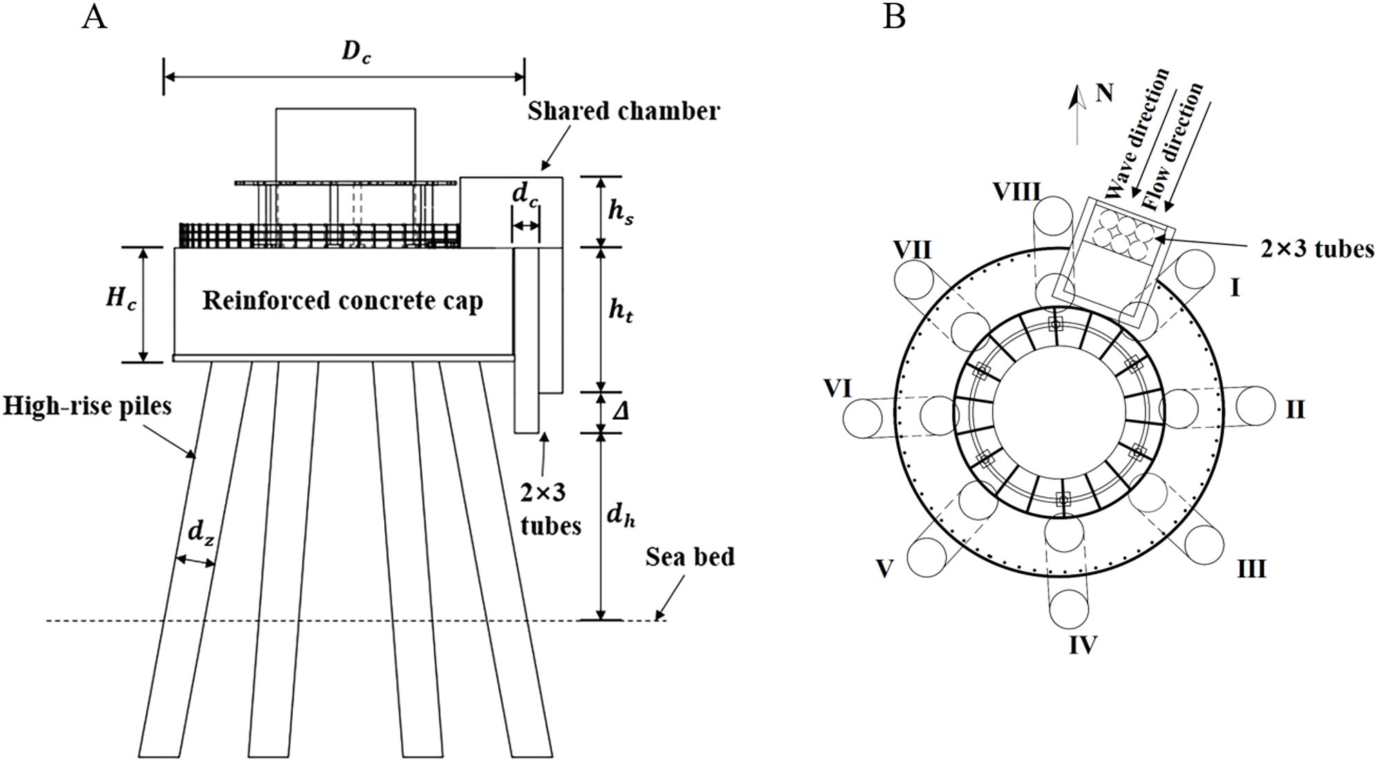
Figure 1. A coupled wind-wave device integrating an OWC-WEC and an offshore wind turbine. (A) Side view; (B) Top view.
The numerical model of the foundation scouring for a coupled wave-wind device is set up using the commercial CFD platform Flow-3D® 11.2 (Flow Science, 2016). The governing equations of the numerical model are the continuity equation and the Reynolds-averaged Naiver-Stokes equations. A cubic computational domain is established for numerical simulations. Since the wind turbine with the reinforced concrete cap and the shared chamber and duct used to install the air turbine do not interact with the water flow, these components are excluded in the numerical model, as they are considered to have no impact on sediment scouring and seabed transportation near the foundation. Eight high-rise piles are deployed, as the actual engineering, with a pile diameter of dz = 2.0 m. The length, width, and height of the computational domain are 45.0 dz, 20.0 dz, and 10.0 dz, respectively. As for the turbulence model, the RNG k-ϵ model has been proven to be suitable for addressing sediment scouring issues (Analytis, 2003; Okhravi et al., 2023; Zheng et al., 2024). Therefore, the RNG k-ϵ turbulence model is employed to close the equations and handle the turbulences near the walls in the present model. The finite volume method is used to discretize the governing equations. The generalized minimal residual method (Steven et al., 1990) with implicit schemes is employed for the pressure-velocity coupling solution. The mesh structures of the coupled model are depicted in Figure 2. Regular hexahedral meshes with a characteristic length of 1.5 dz are used in the numerical model. The meshes near the tubes, piles, and seabed are refined, with a characteristic length of 0.1 dz. The total number of meshes is approximately 3.0 million.
In the computational domain, the left and right boundaries are set as the flow inlet and outflow boundary conditions, respectively. The top and bottom boundaries are set as the pressure outlet and wall boundary conditions. Two side walls are set as the symmetry boundary condition. All environmental parameters refer to the local oceanic conditions in Fujian, China. In the sediment scouring model, the critical Shields number is fixed at 0.05. The incident waves employ a regular wave scenario with a wave height of 1.0 m and a wave period of 5.0 s. The current velocity is fixed at 1.0 m/s. The median sediment diameter is 0.15 mm, and the angle of repose is 32°.
The numerical model is validated by comparing the predictions and experimental results from a previous study (Yeh et al., 2009), which is expected to prove the predicting capability of the interactions between the water and sediment. In the experimental test, the sand bed was paved in a flume to be impacted by an underwater jet flow. The evolution of the scouring pit was observed for a test duration of 20.0 min. An acoustic Doppler velocimetry was used to measure and record the scouring depth at a position near the jet center to avoid affecting the jet flow. The diameter of the jet nozzle was 0.127 m, and the jet flow velocity was 2.05 m/s. The jet height and water depth were 0.76 m and 1.83 m, respectively. The median sediment diameter was 0.258 mm, and the grain density was 2.65×10³ kg/m3.
The comparison of the scour depth variation at different time points at the measuring point in the scouring pit between numerical and experimental results is depicted in Figure 3. The numerical predictions are derived at the jet center, which is slightly different from the experimental setup. At the initial point for t = 3.0 min, the scour depth difference between experimental and numerical results is larger, by approximately 10.1%, which could be caused by the instability of the initial pit. The difference between the numerical and experimental results decreases as the time increases, and the difference at t = 20.0 min decreases to 6.0%. The average difference is approximately 7.1%.
The numerical prediction and experimental result of the final cross-section profile of the scouring pit are compared in Figure 4. Generally, the numerical and experimental final profiles of the scouring pit agree well. The final maximum scouring depth difference between numerical and experimental results is approximately 6.0%. The overall profile difference might be caused by the difference in the measuring point. The angle of the pit slope has a difference of 8.0% in numerical and experimental results. The angle of repose in the numerical model is set at 45°, which was not provided in the experimental report and might cause the numerical error. The comparison results indicate that the numerical model shows its capability to predict sediment scouring for further studies.
The computational domain of the numerical model for the sediment scouring at the foundation of the coupled wind-wave device is depicted in Figure 5. The center of the pile group is located at X = 20.0 dz and Y = 10.0 dz. Six tubes are arranged in two rows and three columns at X = 15.0 dz and Y = 10.0 dz. The tube diameter is dc = 0.8 m. The height difference between two rows of tubes is 1.0 dz, and longer tubes are close to the piles. The computational domain is divided into three parts: water, air, and sediment sub-domains. The sediment, water, and air sub-domains have the heights of 2.5 dz, 6.0 dz, and 1.5 dz, respectively. The distance between the seabed and the longest tube is defined as dh, varying from 1.25 dz to 2.50 dz, 3.75 dz, and 5.00 dz. Eight piles are numbered from I to VIII in a clockwise order. The incident wave and current directions are defined as positive along the X-direction.
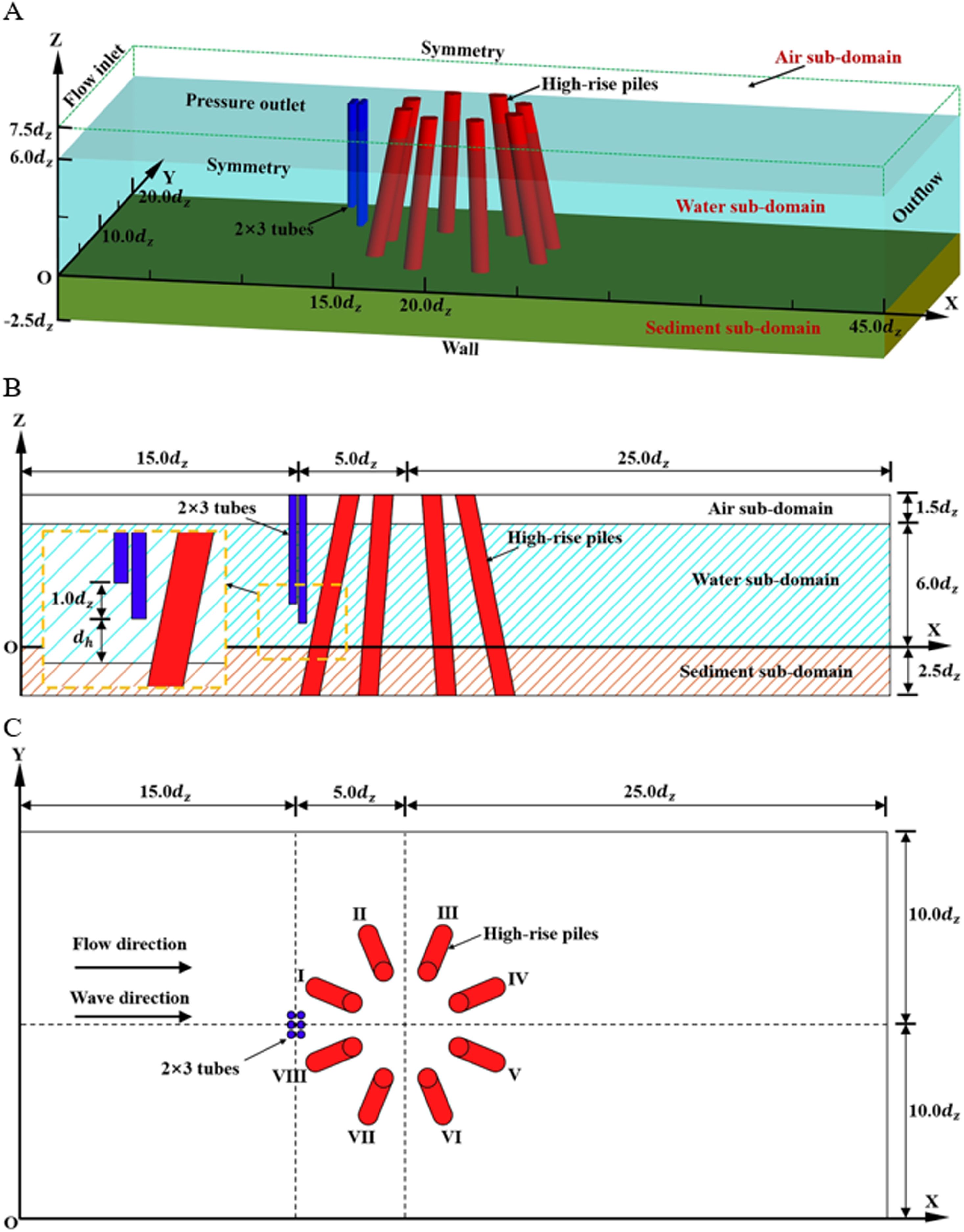
Figure 5. Computational domain of the numerical model. (A) 3D bird view; (B) Side view; (C) Top view.
First, the sediment scouring near the piles of the original wind turbine under the joint actions of incident waves and currents is simulated for comparison. During the trial simulations, it was found that sediment scouring and deposition begin to converge after 30.0 min in this study. Therefore, the simulation time is fixed at 30.0 min, and the time points at 5.0 min, 10.0 min, 20.0 min, and 30.0 min are selected as the typical representing time points for analysis of all results.
The water flow velocity near the seabed is a critical parameter affecting sediment incipient motion and its scouring and deposition. Therefore, the velocity contours of the water flow right above the seabed on the X-Y plane (Z = 0) at four typical time points are depicted in Figure 6. The distribution characteristics of the water flow velocities above the seabed for four typical time points have no significant difference, indicating that the incident waves have minor influences on the flow field near the seabed. In addition, the distribution of the water flow velocity in the X-Y plane is symmetrical to the Y = 10.0 dz axis. The velocities at two sides of the piles are accelerated with larger values, which are more significant for piles I, II, VII, and VIII. At the positions in front of and in the rear of the piles, the water flow velocities are relatively lower. Piles III and VI are in the wake of piles II and VII, respectively, and the velocities near the piles are significantly affected by the wake flow. Furthermore, the lowest velocities can be found in the wake of piles IV and V. A similar phenomenon has also been observed in studies on the coupled group pile foundations (Liu et al., 2022).
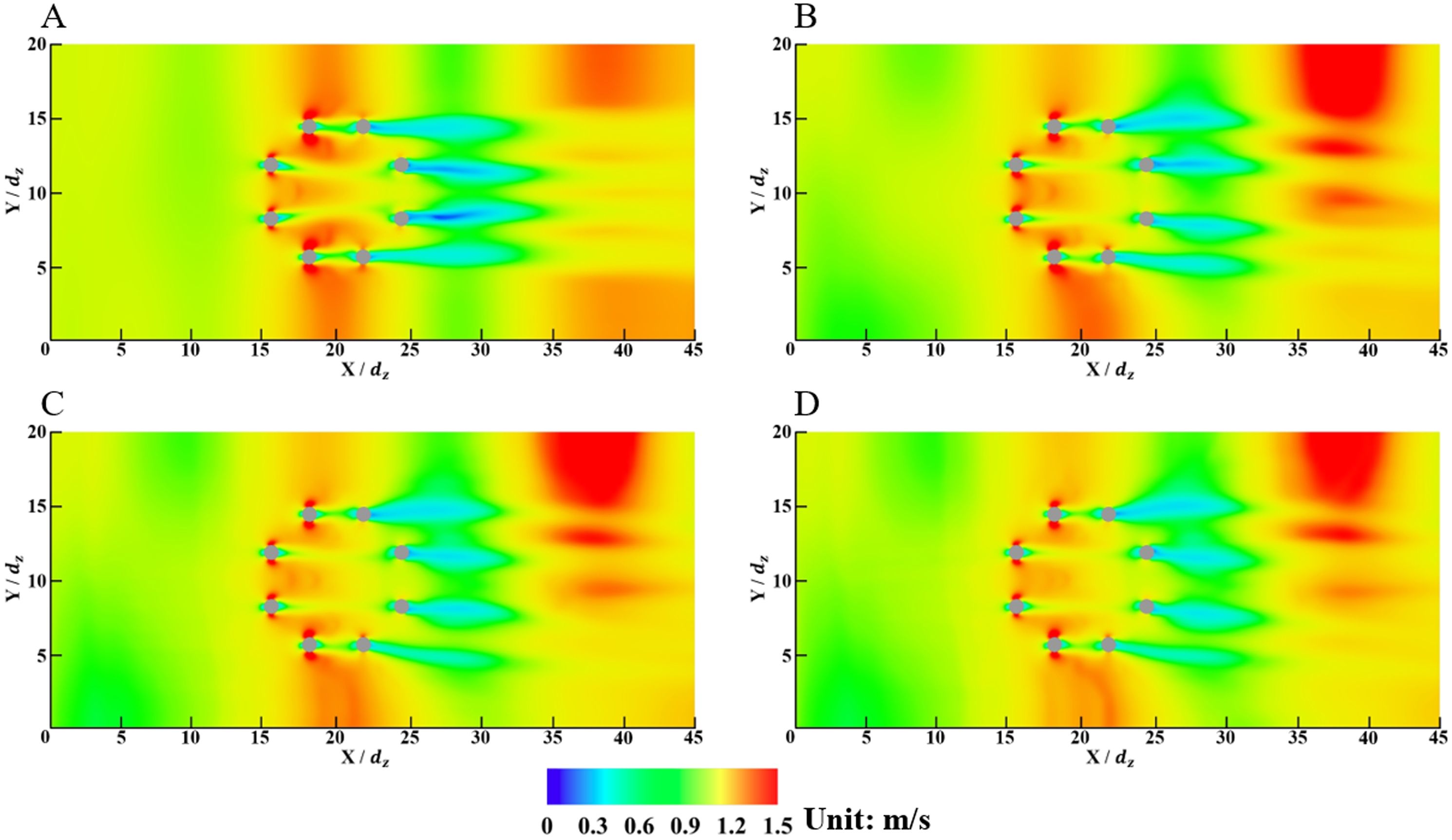
Figure 6. Velocity contours of the water flow on an X-Y plane for the original wind turbine (Z = 0). (A) t = 5.0 min; (B) t = 10.0 min; (C) t = 20.0 min; (D) t = 30.0 min.
As the flow field is symmetrical to the axis of Y = 10.0 dz in the computational domain, the velocity contours of the water flow on the X-Z planes are only shown in half of the domain in Figure 7. Two typical X-Z planes are employed: Y = 11.75 dz including the piles I and IV and Y = 14.50 dz including piles II and III. The velocity contours can clearly show the influences of incident waves on the flow field. As the distance between piles I and IV is large, as shown in Figure 7A, the flow field between two piles is affected less by the front one, resulting in more turbulences and larger velocity values above the seabed between piles I and IV. For piles II and III, as shown in Figure 7B, the distance is relatively small, and a low-velocity zone can be observed between the piles with a limited area.
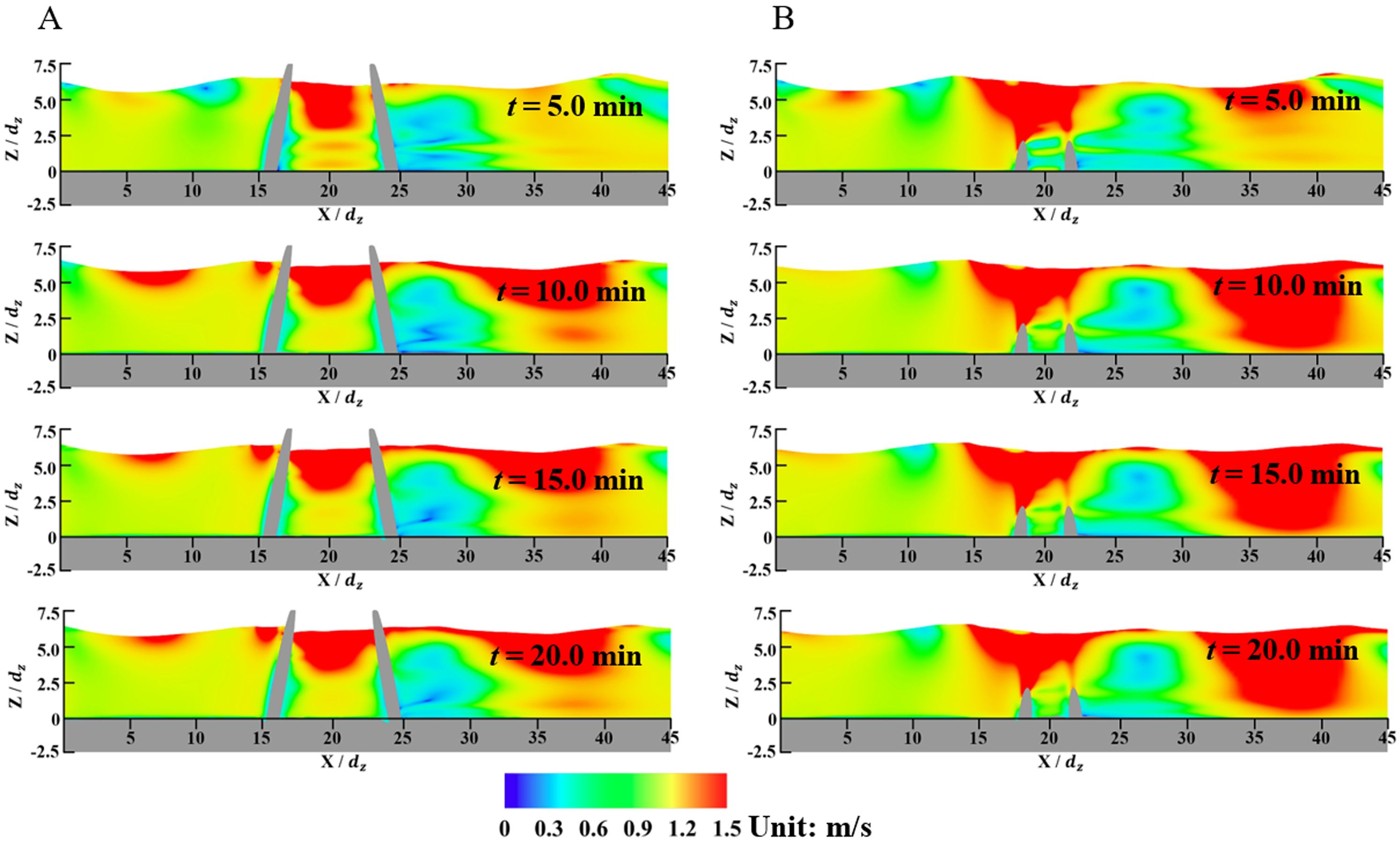
Figure 7. Velocity contours of the water flows on two typical X-Z planes for the original wind turbine. (A) In the plane of Y = 11.75 dz; (B) In the plane of Y = 14.50 dz.
The development of sediment scouring and deposition near the piles in the initial 30.0 min can be reflected by the depth variation contours in Figure 8. The basic distribution characteristics at four typical time points are similar, with different scouring and deposition values. The sediment scouring and deposition are also symmetric to the Y = 10.0 dz axis. The sediment scouring can be observed at two sides of the piles because of incident water flow velocity enhancement. On the other hand, the sediment depositions are found in the front and back of the piles, where the water flow velocities are observed to be reduced, especially for piles III and VI, which have the most deposition depths.
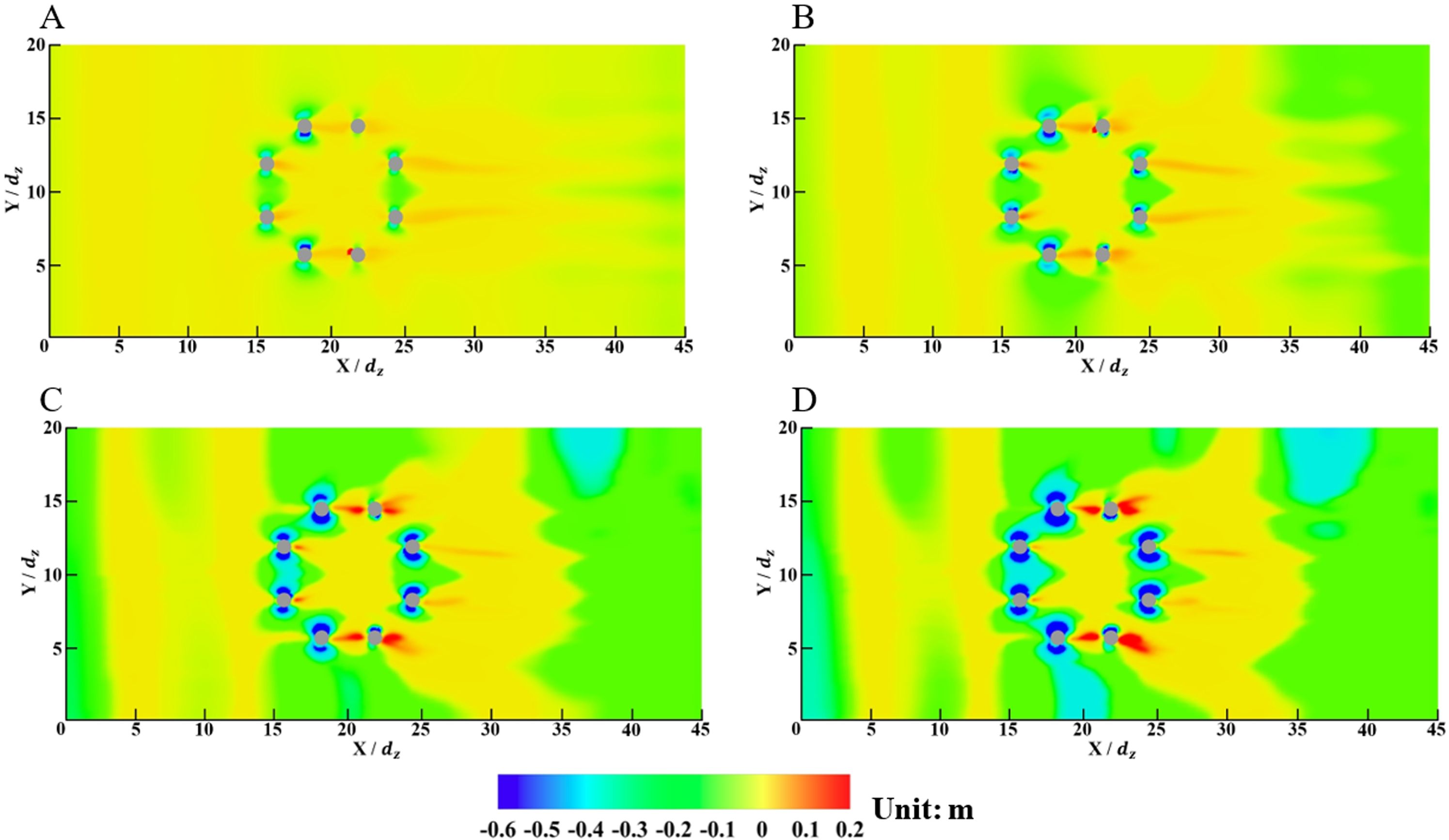
Figure 8. Depth contours from the reference plane near the piles for the original wind turbine (Z = 0). (A) t = 5.0 min; (B) t = 10.0 min; (C) t = 20.0 min; (D) t = 30.0 min.
The seabed depth variations in the 30.0 min calculation duration at four points which are near four piles I to IV in a half side with the largest scouring depth are depicted in Figure 9. The coordinate (in the X-Y plane) details of the monitoring points are listed as the follows: (15.5 dz, 11.5 dz) for Pile I; (18.1 dz, 13.8 dz) for Pile II; (21.8 dz, 13.9 dz) for Pile III; (24.5 dz, 11.6 dz) for Pile IV. It can be observed that the scouring depths for Pile III are significantly smaller than the points for other piles during the calculation period. From the velocity analysis in the contour figures, it could be concluded that Pile III is sheltered by Pile II and the velocities at two sides of the pile reduce gradually, resulting in a reduction in the sediment carrying capability of the water flow and a settlement of the suspended load near the pile. On the other hand, the distance between piles I and IV is relatively larger, and the sheltered effects of Pile I to the Pile IV are relatively weak, resulting in more scouring near Pile IV than that near Pile III. For piles arranged in a front-back configuration, the scour depth increases with the distance between the piles, which aligns with the findings of this study (Liu et al., 2022). The converged scouring depth for the four points are 0.42 dz, 0.51 dz, 0.32 dz, and 0.52 dz, respectively.
The velocity contours of the water flow near the piles of the wind-wave coupled device on an X-Y plane (Z = 0) at t = 30.0 min for various values of dh are depicted in Figure 10. The overall effects of the distance between the tube ends and seabed on the velocity distribution of the water flow near the piles are minor. As the chamber tubes are close to the seabed (dh = 1.25 dz), an enhancement of the large-velocity area in the rear of the tubes can be observed, which is caused by an increase in the water flow rate passing the tube ends because of the blockage of the added structures near the piles. In general, the prediction results show that the installation of the tube array has little influence on the flow field near the piles, indicating that the relative scale of the tube array is small compared to the original piles, which are the primary critical factors affecting the water flow field. The velocity contours of the water flow in the rear of the tube array in an X-Z plane (Y = 10.0 dz) for various values of dh are depicted in Figure 11. The tube array has significant sheltered effects on the near field in their rear area with a reduction of the water flow velocity. The influence of sheltered effects on scouring depth was also found in previous studies (Amini et al., 2012; Ataie-Ashtiani and Beheshti, 2006). In general, in the X-Z plane, the installation of the OWC system also has limited influence on the water flow field in the rear of the tube array.

Figure 10. Velocity contours of the water flow on an X-Y plane for the wind-wave coupled device (Z = 0). (A) dh = 1.25 dz; (B) dh = 2.50 dz; (C) dh = 3.75 dz; (D) dh = 5.00 dz.
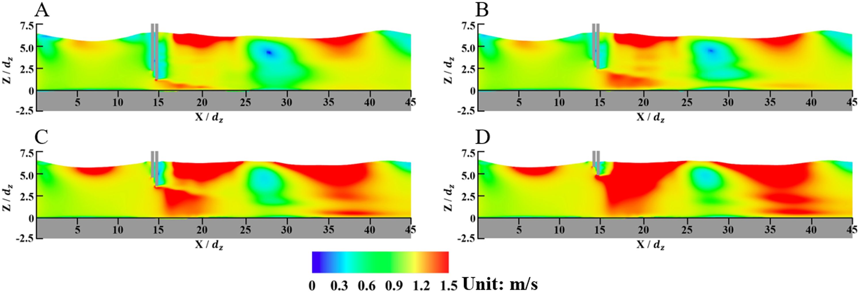
Figure 11. Velocity contours of the water flow in an X-Z plane for the wind-wave coupled device (Y = 10.0 dz). (A) dh = 1.25 dz; (B) dh = 2.50 dz; (C) dh = 3.75 dz; (D) dh = 5.00 dz.
The velocity contours of the water flow near the piles in two typical X-Z planes at t = 30.0 min for various values of dh are depicted in Figure 12. The flow fields near the piles for the wind-wave coupled device are similar to those for the original wind turbine in Figure 7. In addition, because of the blockage effects of the tube array, as the distance between the tube ends and seabed is relatively small, the velocities between the piles I and IV are enhanced, which might influence the sediment scouring and deposition near the piles. On the other hand, the sheltered effects of Pile II on Pile III are still evident, resulting in an area with relatively small velocities. The tube array has no significant influence on the flow field distribution in this area.
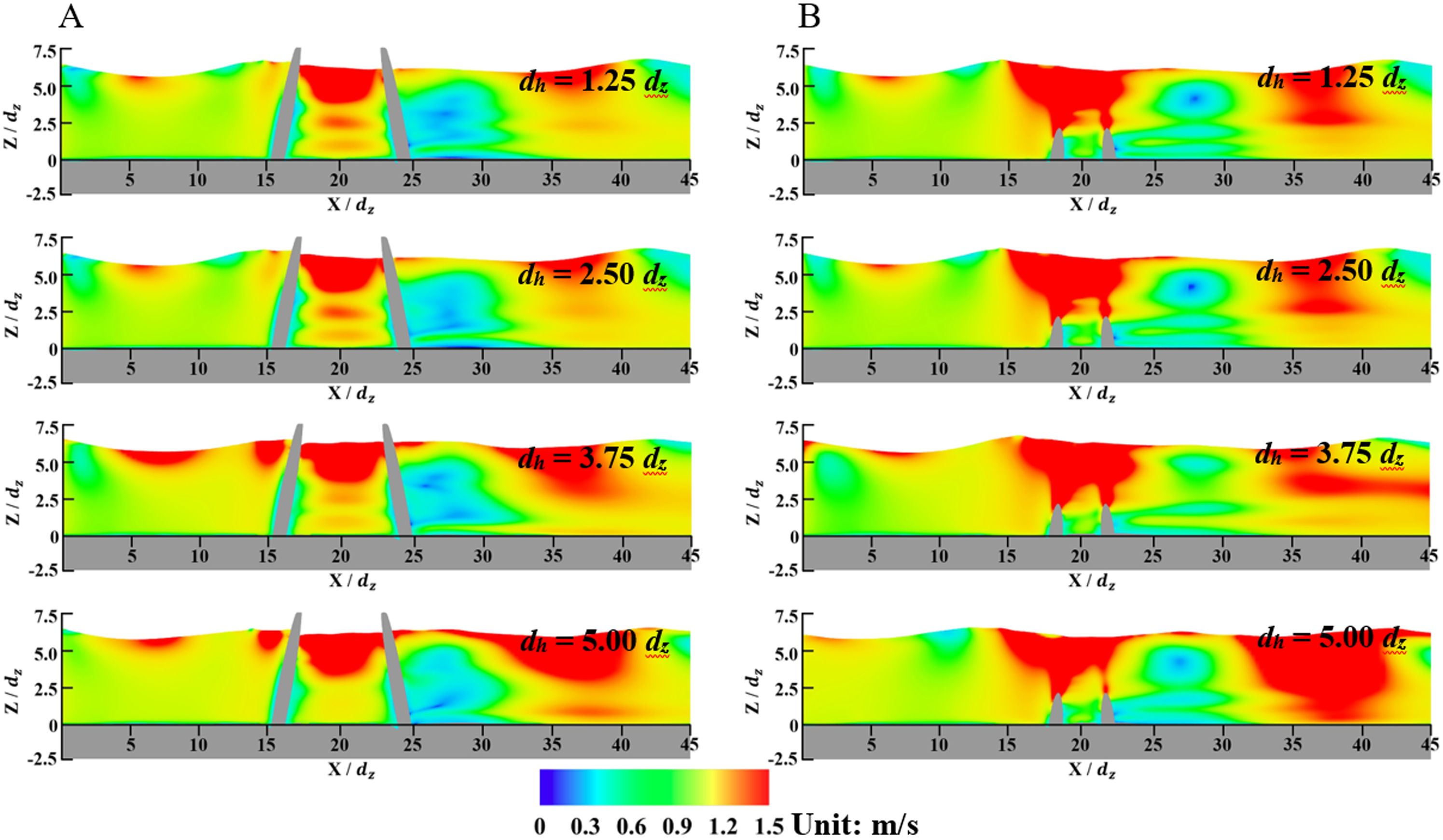
Figure 12. Velocity contours of the water flows on two typical X-Z planes for the wind-wave coupled device. (A) In the plane of Y = 11.75 dz; (B) In the plane of Y = 14.50 dz.
The depth variations near the piles for the wind-wave coupled device at t = 30.0 min for various values of dh are depicted in Figure 13. Compared to the depth variations for the original wind turbine in Figure 8, the differences of the sediment scouring and depositions near the piles are minor. The positions of the maximum scouring points near the piles have few differences. For instance, the differences in the positions near piles I and II for dh = 1.25 dz and dh = 2.50 dz are both less than 1% of the pile diameter, which can be ignored considering possible errors in the numerical simulations. Therefore, even for the wind-wave coupled device, the piles still play a critical role in the sediment movement nearby. In addition, for dh = 1.25 dz and dh = 2.50 dz, the scouring area surrounded by the piles becomes larger because of the velocity enhancement of the water flow caused by the tube array. The scouring depths are limited with the values less than 0.1 dz. As dh > 2.50 dz, the scouring areas and depths are approximately the same as those for the original wind turbine.
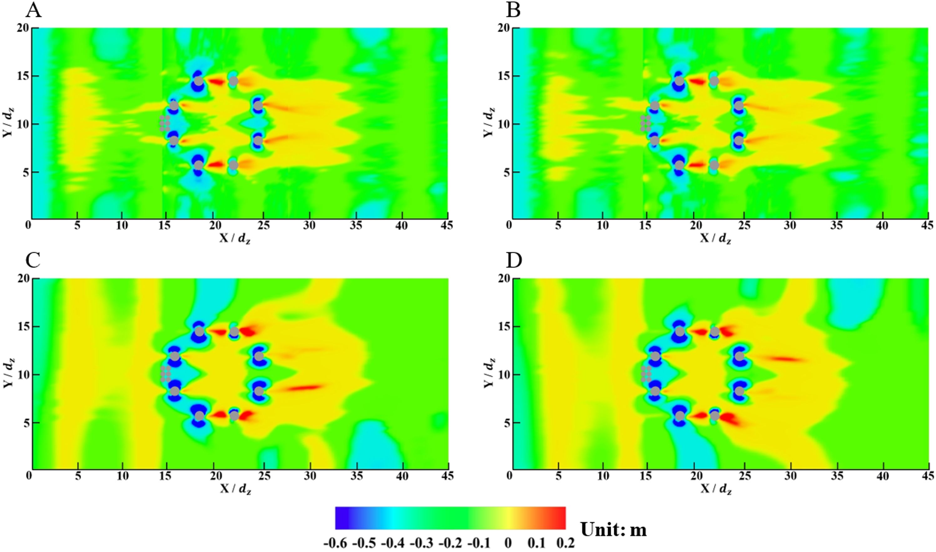
Figure 13. Depth contours from the reference plane near the piles for the wind-wave coupled device (Z = 0). (A) dh = 1.25 dz; (B) dh = 2.50 dz; (C) dh = 3.75 dz; (D) dh = 5.00 dz.
The depth variations of the maximum scouring points near different piles during the simulation period for the coupled wind-wave device are depicted in Figure 14. In general, the existence of the tube array can accelerate the development of the scouring depth. For piles I to III, the maximum scouring depths are close to those for the original wind turbine. On the other hand, for the Pile IV and dh = 5.00 dz, the OWC tubes have little influence on the maximum scouring depth. As the dh value decreases, the maximum scouring depth shows a decreasing varying trend, and the scouring depth reduces 22.8% at t = 30.0 min compared to the case without any tubes. As mentioned, the scouring area surrounded by the piles increases, and the water flow can carry more sediment. When the water flow arrives at Pile IV, the velocity reduces because of the blockage of the pile, resulting in more sediment settlements.
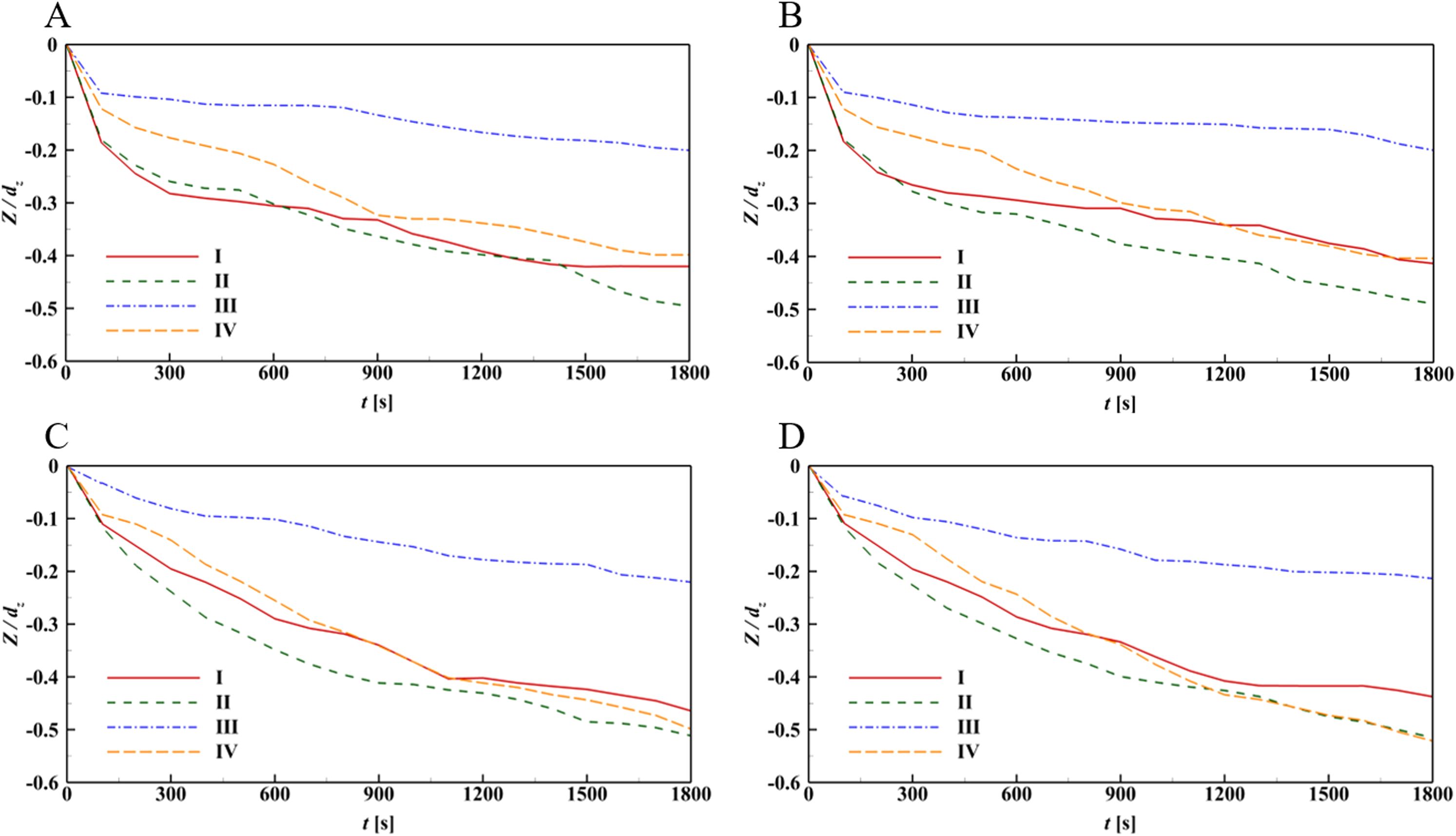
Figure 14. Depth variations at the maximum scouring points near the piles for the wind-wave coupled device. (A) dh = 1.25 dz; (B) dh = 2.50 dz; (C) dh = 3.75 dz; (D) dh = 5.00 dz.
The maximum scouring depths at the relative points near different piles for various values of dh at t = 30.0 min are compared in Figure 15, where Zmax represents the maximum scouring depth near different piles. In general, installing the OWC system makes a minor contribution to the maximum scouring depths near different piles. On the contrary, as the tube end is close to the seabed, the existence of the tube array can significantly reduce the scouring depths near the piles, which is beneficial to the stability and reliability of the piles. No matter whether the OWC system is installed on the foundation of the offshore wind turbine, the sediment scouring depths near piles I&II and VII&VIII are relatively larger, and the protections should be conducted using various methods on the seabed near these piles.
A numerical model on the sediment scouring and deposition prediction near the piles for the fixed offshore wind turbine and an integrated OWC wave energy converter was established based on a commercial CFD platform, Flow 3D®, which was validated using experimental laboratory test data on a typical scouring problem. The sediment scouring and deposition near the foundation of an original wind turbine and a wind-wave coupled device under the joint actions of incident waves and currents for various tube end lengths are studied numerically.
Under the combined effect of waves and currents, the scouring phenomenon mainly occurs on both sides of the piles, while the deposition phenomenon takes place at the rear of the piles. Due to the relatively small distance between the piles in the direction of incident waves and currents, the blockage effect is significant, which leads to a reduction in scouring depth. When the piles are arranged in a staggered pattern, the blockage effect is reduced, and the flow field becomes more turbulent as it flows through the pipes, resulting in an increase in scouring depth.
The distance between the tube ends and the seabed has a notable impact on the scouring. When the distance is less than 2.5 times the pile diameter, the scouring area near the foundation is enlarged, and the development of the scouring is accelerated. However, the overall distribution of scour and deposition around each pile remains largely unaffected, and there is no significant increase in the maximum scouring depth near the piles. Additionally, although the OWC tubes increase the flow velocity around the seabed, the extent of this increase and the affected area are relatively small. The tubes also create a noticeable shielding effect behind them, which significantly reduces the scouring depth near the piles farther away. The closer the bottom of the tubes is to the seabed, the more pronounced the shielding effect becomes. This suggests that in engineering applications of the coupled wind and wave device, concerns about the bottom of the OWC device being too close to the seabed and causing increased foundation scour are unfounded.
Overall, the OWC tube arrays, or other configurations integrated with the wind turbine, have minimal influence on the scouring depth of the near piles and might cause a reduction in the maximum scouring depth near the piles at the far end, which is beneficial to the stability and reliability of the pile foundation of the coupled device. In the future, additional factors, such as the effects of different wind turbine foundations, marine environmental conditions, seabed geological conditions, and device scales on the scouring, will be considered to provide more comprehensive investigations of the device.
The original contributions presented in the study are included in the article/supplementary material. Further inquiries can be directed to the corresponding author.
XC: Conceptualization, Investigation, Methodology, Writing – original draft. XY: Data curation, Investigation, Resources, Writing – review & editing. XD: Funding acquisition, Investigation, Visualization, Writing – review & editing. CX: Investigation, Methodology, Software, Writing – original draft. ZL: Conceptualization, Funding acquisition, Investigation, Supervision, Writing – review & editing. LW: Data curation, Software, Validation, Writing – review & editing.
The author(s) declare that financial support was received for the research and/or publication of this article. This work was supported by the Shandong Provincial Natural Science Foundation (Grant No. ZR2023QE110), National Natural Science Foundation of China (Grant Nos. 52301350 and 52471308) and the Project of Key Technology Research and Application of Fujian Coastal Wind and Wave Combined System (Grant No. 20240063).
Authors XC and XY were employed by Huadian Fujian Wind Power Co., Ltd.
The remaining authors declare that the research was conducted in the absence of any commercial or financial relationships that could be construed as a potential conflict of interest.
The author(s) declare that no Generative AI was used in the creation of this manuscript.
All claims expressed in this article are solely those of the authors and do not necessarily represent those of their affiliated organizations, or those of the publisher, the editors and the reviewers. Any product that may be evaluated in this article, or claim that may be made by its manufacturer, is not guaranteed or endorsed by the publisher.
Ax: Area fraction of the fluid in x direction
Sc: Reciprocal of the turbulent Schmidt number
Ay: Area fraction of the fluid in y direction
T: Wave period
Az: Area fraction of the fluid in z direction
u: Velocity components in the x direction
Cs,I: Mass concentration of the suspended sediment
uf: Dynamic viscosity of water
dc: Tube diameter
ulift: Entrainment lift velocity of the sediment
dh: Distance between the seabed and the longest tube
usettling: Settling velocity of the sediment
di: Sediment median diameter
us,I: Velocity of the suspended load
dz: Pile diameter
v: Velocity components in the y direction
D: Sediment diffusion coefficient
νf: Kinematic viscosity of water
Dc: Diameter of the reinforced concrete cap
νρ: Coefficient of momentum diffusion
f: Components of the viscous acceleration
VF: Volume fraction of the flow section
g: Gravitational acceleration
w: Velocity components in the z direction
G: Components of the gravitational acceleration
α: Entrainment parameter
hs: Height of the shared chamber
β: Bed load coefficient
ht: Height of the short tubes
Δ: Difference of the short and long tubes
H: Wave height
θcr: Threshold Shields number
Hc: Height of the reinforced concrete cap
θi: Local Shields number
Ns: Outward pointing normal to the packed bed interface
ρ: Water density
p: Pressure of water
ρi: Sediment density
qb,I: Bed load discharge
τ: Local bed shear stress
RDIF: Turbulent diffusion term
Φi: Coefficient of the bed load discharge.
Amini A., Melville B. W., Ali T. M., Ghazali A. H. (2012). Clear-water local scour around pile groups in shallow-water flow. J. Hydraul. Eng. 138, 177–185. doi: 10.1061/(asce)hy.1943-7900.0000488
Analytis G. T. (2003). Implementation of the renormalization group (RNG) k-ϵ turbulence model in GOTHIC/6.1b: Solution methods and assessment. Ann. Nucl. Energy 30, 349–387. doi: 10.1016/S0306-4549(02)00061-0
Ataie-Ashtiani B., Beheshti A. A. (2006). Experimental investigation of clear-water local scour at pile groups. J. Hydraul. Eng. 132, 1100–1104. doi: 10.1061/(asce)0733-9429(2006)132:10(1100
Bordbar A., Sharifi S., Hemida H. (2021). Investigation of the flow behaviour and local scour around single square-shaped cylinders at different positions in live-bed. Ocean Eng. 238, 109772. doi: 10.1016/j.oceaneng.2021.109772
De Azevedo H. D. M., Araújo A. M., Bouchonneau N. (2016). A review of wind turbine bearing condition monitoring: State of the art and challenges. Renew. Sustain. Energy Rev. 56, 368–379. doi: 10.1016/j.rser.2015.11.032
Dixen M., Sumer B. M., Fredsøe J. (2013). Numerical and experimental investigation of flow and scour around a half-buried sphere. Coast. Eng. 73, 84–105. doi: 10.1016/j.coastaleng.2012.10.006
Fernandez Luque R., Van Beek R. (1976). Erosion and transport of bed-load sediment. J. Hydraul. Res. Rech. Hydraul. 14, 127–144. doi: 10.1080/00221687609499677
Flow Science. (2016). FLOW-3D® Version 11.2 Users Manual. Santa Fe, NM: Flow Science, Inc. Available online at: https://www.flow3d.com.
Hu R., Wang X., Liu H., Lu Y. (2021). Experimental study of local scour around tripod foundation in combined collinear waves-current conditions. J. Mar. Sci. Eng. 9 (12), 1373. doi: 10.3390/jmse9121373
Kim H. S., Nabi M., Kimura I., Shimizu Y. (2014). Numerical investigation of local scour at two adjacent cylinders. Adv. Water Resour. 70, 131–147. doi: 10.1016/j.advwatres.2014.04.018
Li J., Guo Y., Lian J., Wang H. (2022). Scour effects on the bearing capacity of multi-bucket jacket foundation for offshore wind turbines. Ocean Eng. 259, 111848. doi: 10.1016/j.oceaneng.2022.111848
Liang F., Wang C., Huang M., Wang Y. (2017). Experimental observations and evaluations of formulae for local scour at pile groups in steady currents. Mar. Georesources Geotechnol. 35, 245–255. doi: 10.1080/1064119X.2016.1147510
Liu D., Diplas P., Fairbanks J. D., Hodges C. C. (2008). An experimental study of flow through rigid vegetation. J. Geophys. Res. Earth Surf. 113, 1–16. doi: 10.1029/2008JF001042
Liu M. M., Wang H. C., Tang G. Q., Shao F. F., Jin X. (2022). Investigation of local scour around two vertical piles by using numerical method. Ocean Eng. 244, 110405. doi: 10.1016/j.oceaneng.2021.110405
Mastbergen D. R., Van Den Berg J. H. (2003). Breaching in fine sands and the generation of sustained turbidity currents in submarine canyons. Sedimentology 50, 625–637. doi: 10.1046/j.1365-3091.2003.00554.x
Menéndez-Vicente C., López-Querol S., Bhattacharya S., Simons R. (2023). Numerical study on the effects of scour on monopile foundations for Offshore Wind Turbines: The case of Robin Rigg wind farm. Soil Dyn. Earthq. Eng. 167, 107803. doi: 10.1016/j.soildyn.2023.107803
Okhravi S., Gohari S., Alemi M., Maia R. (2023). Numerical modeling of local scour of non-uniform graded sediment for two arrangements of pile groups. Int. J. Sediment Res. 38, 597–614. doi: 10.1016/j.ijsrc.2023.04.002
Olsen N. R. B., Kjellesvig H. M. (1998). Three-dimensional numerical flow modeling for estimation of maximum local scour depth. J. Hydraul. Res. 36, 579–590. doi: 10.1080/00221689809498610
Qi W. G., Gao F. P. (2014). Physical modeling of local scour development around a large-diameter monopile in combined waves and current. Coast. Eng. 83, 72–81. doi: 10.1016/j.coastaleng.2013.10.007
Rehman S., Alhems L. M., Alam M. M., Wang L., Toor Z. (2023). A review of energy extraction from wind and ocean: Technologies, merits, efficiencies, and cost. Ocean Eng. 267, 113192. doi: 10.1016/j.oceaneng.2022.113192
Roulund A., Sumer B. M., Fredsøe J., Michelsen J. (2005). Numerical and experimental investigation of flow and scour around a circular pile. J. Fluid Mech. 534, 351–401. doi: 10.1017/S0022112005004507
Steven F., Thomas A., Paul E. (1990). A taxonomy for conjugate gradient methods. SIAM J. Numer. Anal. 27, 1542–1568. doi: 10.1137/0727091
Wan L., Moan T., Gao Z., Shi W. (2024). A review on the technical development of combined wind and wave energy conversion systems. Energy 294, 130885. doi: 10.1016/j.energy.2024.130885
Wang W., Yang S., Gao C., Huang W. (2020). Influence of turbulence schmidt number on exit temperature distribution of an annular gas turbine combustor using flamelet generated manifold. J. Therm. Sci. 29, 58–68. doi: 10.1007/s11630-019-1248-8
Welzel M., Schendel A., Hildebrandt A., Schlurmann T. (2019). Scour development around a jacket structure in combined waves and current conditions compared to monopile foundations. Coast. Eng. 152, 103515. doi: 10.1016/j.coastaleng.2019.103515
Yang X., Liu N., Zhang P., Guo Z., Ma C., Hu P., et al. (2019). The current state of marine renewable energy policy in China. Mar. Policy 100, 334–341. doi: 10.1016/j.marpol.2018.11.038
Yeh P. H., Chang K. A., Henriksen J., Edge B., Chang P., Silver A., et al. (2009). Large-scale laboratory experiment on erosion of sand beds by moving circular vertical jets. Ocean Eng. 36, 248–255. doi: 10.1016/j.oceaneng.2008.11.006
Yu T., Lian J., Shi Z., Wang H. (2016). Experimental investigation of current-induced local scour around composite bucket foundation in silty sand. Ocean Eng. 117, 311–320. doi: 10.1016/j.oceaneng.2016.03.045
Yu T., Zhang Y., Zhang S., Shi Z., Chen X., Xu Y., et al. (2019). Experimental study on scour around a composite bucket foundation due to waves and current. Ocean Eng. 189, 106302. doi: 10.1016/j.oceaneng.2019.106302
Zhang F., Chen X., Feng T., Wang Y., Liu X., Liu X. L. (2022). Experimental study of grouting protection against local scouring of monopile foundations for offshore wind turbines. Ocean Eng. 258, 111798. doi: 10.1016/j.oceaneng.2022.111798
Zhang F., Chen X., Feng T., Zhang Y. (2023). Experimental investigation of the horizontal bearing capacity of offshore wind-turbine monopiles with grouting protection against scouring. Ocean Eng. 280, 114848. doi: 10.1016/j.oceaneng.2023.114848
Zhang Q., Zhou X. L., Wang J. H. (2017). Numerical investigation of local scour around three adjacent piles with different arrangements under current. Ocean Eng. 142, 625–638. doi: 10.1016/j.oceaneng.2017.07.045
Zhao M., Cheng L., Zang Z. (2010). Experimental and numerical investigation of local scour around a submerged vertical circular cylinder in steady currents. Coast. Eng. 57, 709–721. doi: 10.1016/j.coastaleng.2010.03.002
Keywords: offshore wind turbine, wave energy, oscillating water column, coupled device, sediment scouring, numerical simulation
Citation: Chen X, Yu X, Dong X, Xu C, Liu Z and Wang L (2025) Sediment scouring at the foundation of a coupled wind and wave device: a numerical study. Front. Mar. Sci. 12:1556924. doi: 10.3389/fmars.2025.1556924
Received: 07 January 2025; Accepted: 03 March 2025;
Published: 24 March 2025.
Edited by:
Giovanni Bracco, Polytechnic University of Turin, ItalyReviewed by:
Carlos Pérez-Collazo, University of Vigo, SpainCopyright © 2025 Chen, Yu, Dong, Xu, Liu and Wang. This is an open-access article distributed under the terms of the Creative Commons Attribution License (CC BY). The use, distribution or reproduction in other forums is permitted, provided the original author(s) and the copyright owner(s) are credited and that the original publication in this journal is cited, in accordance with accepted academic practice. No use, distribution or reproduction is permitted which does not comply with these terms.
*Correspondence: Chuanli Xu, eHVjaHVhbmxpQHN0dS5vdWMuZWR1LmNu
Disclaimer: All claims expressed in this article are solely those of the authors and do not necessarily represent those of their affiliated organizations, or those of the publisher, the editors and the reviewers. Any product that may be evaluated in this article or claim that may be made by its manufacturer is not guaranteed or endorsed by the publisher.
Research integrity at Frontiers

Learn more about the work of our research integrity team to safeguard the quality of each article we publish.