Abstract
The underwater manipulator is a versatile tool commonly used for various underwater operations. In this study, we developed a heavy-duty hydraulic manipulator capable of operating at full ocean depth. The overall system design integrates both the mechanical structure and the electric control system. The master arm controls the slave arm by transmitting control signals to the controller and valve box. The structural design of the elbow and wrist joints has been optimized to enhance the manipulator's underwater performance and operational range. Laboratory tests demonstrated the manipulator’s excellent response consistency and tracking capability across a wide range of motion. During sea trials in the Mariana Trench, the manned submersible Fendouzhe successfully deployed the manipulator, showcasing its exceptional ability to complete complex tasks.
1 Introduction
The hadal zone is the deepest part of the earth’s oceans, and its seawater depth exceeds 6000 meters in the ocean area, covering 1% to 2% of the seafloor area and 45% of the vertical depth of the ocean (Meadows et al., 1988; Thurman, 1996; Ramirez-Llodra et al., 2010). It is an essential part of the marine ecosystem. The hadal zone is an extreme ecological environment such as high pressure, low temperature, and no light. Scientists have also found signs of life in such sea areas (Deckert et al., 1998; Jorgensen and Boetius, 2007; Orcutt et al., 2011; Jamieson, 2015; Flemming and Wuertz, 2019). The microorganisms living in such a harsh environment are very different, and life in this extreme environment has received more and more attention (Corinaldesi, 2015). The hadal sediments contain a large number of microorganisms, and their great diversity has become a huge treasure trove of natural biological products (Kim et al., 2017). Over the past fifty years, about 20,000 natural products of marine organisms have been discovered (Skropeta, 2008; Hu et al., 2011; Skropeta and Wei, 2014; Carroll et al., 2019). Many have anti-tumor, anti-cell aging, antibacterial, and antiviral activities (Haefner, 2003; Bhatnagar and Kim, 2010; Thornburg et al., 2010; Russo et al., 2015), and dozens of marine anticancer drugs have entered the clinical or preclinical research stage (Lichota and Gwozdzinski, 2018; Khalifa et al., 2019). The hadal zone contains many precious resources, and the exploration of the abyss is of great significance for the study of the development of the earth. The exploration technology of advancing into the hadal zone has become the key to the development of marine resources in various countries in the world. The exploration of the hadal zone requires advanced marine engineering technology (Wynn et al., 2014), especially the exploration technology for the full ocean deep environment (Li et al., 2021).
The underwater manipulator is a typical underwater operation tool, which is widely used to perform underwater tasks (Dunnigan et al., 1996; Luo et al., 2014; Zhang et al., 2016). It plays an irreplaceable role in marine scientific research and resource development (Dunnigan et al., 1996; Clegg et al., 2001; Li et al., 2021). In the process of ocean exploration, people usually use manipulators to operate and retrieve underwater objects (Jones, 2009; Capocci et al., 2017), which have the characteristics of high precision, strong operation ability, and strong load capacity (Luo et al., 2014; Sivcev et al., 2018). Some industrial companies, such as Hydro Lek (2011); Schilling Robotics (2011), and ISE Ltd (2011)), have commercialized manipulators, but they are designed for depth classes of 6000 meters or less.
The research on deep-sea manipulator systems is an important research field. Kurumaya et al. (2018)) improved the wrist joint mechanism of a hydraulically driven soft robot and conducted hydrostatic pressure experiments equivalent to 2300 meters depth, which can be used to satisfy precise manipulation in the deep sea. Bai et al. (2021) designed a deep-sea electric manipulator with a working depth of 3000 meters, with four degrees of freedom and the function of gripping objects, and modeled and optimized its vicious power. Many studies complement the dynamic modeling of deep-sea manipulators (Dong, 2007; Andrioaia et al., 2013; Li et al., 2020). Zhang et al. (2022) proposed a rate control scheme for the flow limitation of the master-slave hydraulic manipulator. According to the operation method of the hydraulic manipulator, a highly adaptive hydraulic manipulator rate controller was designed, the experimental results show that the speed error is significantly reduced, thus avoiding the vibration of the manipulator and the performance of the hydraulic manipulator are improved. Yao (Yao and Wang, 2012) designed a seven-function underwater manipulator for a working depth of 3000 meters, initially designed its configuration and control system, and realized fault diagnosis. Zhang (Zhang et al., 2013, 2014) proposed a master-slave hydraulic manipulator that can be used in the deep sea at a depth of 7000 meters and introduced the design and control experiments of the manipulator in detail. It realizes rotary drive, multi-channel oil, cable passing, and rotation angle measurement through the designed twin-screw pair swing-type rotary actuator. Chen et al. (2019) designed a hydraulic manipulator for Mariana Trench exploration. Three basic modules of the slave arm including a linear cylinder, a single-vane swing cylinder, and a new wrist joint are designed.
In this paper, we developed a full ocean depth hydraulic manipulator with heavy-duty capacity. The mechanical structure and electronic control system are developed respectively. We designed the structure of the elbow joint and wrist joint to improve the performance of the manipulator to operate normally at a depth of 11000 meters. Furthermore, laboratory and pressure experiments are conducted to validate the system. Finally, the manned submersible Fendouzhe carried the manipulator diving for sea trials in the Mariana Trench.
2 Methods
The extreme hydrostatic pressure in deep-sea environments can lead to pressure losses in hydraulic systems, diminishing the driving capacity of actuators. By calculating the corresponding pressure loss in the pipeline at the particular sea depth, suitable pressure loss compensation measures can be applied. For the loss of corner bend pipe, which is shown in Figure 1A, its empirical formula is shown in Equation 1, and the local loss coefficient () is determined by the size of the bend angle α.
Figure 1

Schematic diagram of the pipe bend angle. (A) the corner bend pipe; (B) the round corner bend pipe.
For the loss of round corner bend pipe, which is shown in Figure 1B, its empirical formula is shown in Equation 2.
In Equation 2, D is bend diameter; α is turning angle; R is curvature radius of the axis of bend.
When α = 90°, ξ and d/R are shown in Table 1.
Table 1
| 0.2 | 0.4 | 0.5 | 0.6 | 0.7 | 0.8 | 0.9 | 1.0 | 1.2 | 1.4 | 1.6 | 1.8 | 2.0 | |
|---|---|---|---|---|---|---|---|---|---|---|---|---|---|
| 0.13 | 0.14 | 0.15 | 0.16 | 0.18 | 0.21 | 0.24 | 0.29 | 0.44 | 0.66 | 0.98 | 1.41 | 1.98 |
Local loss coefficient () and Ratio of diameter to radius of curvature(d/R).
In the hydraulic control system of the seven-function manipulator, the pressure loss mainly exists in three places, the right-angle loss, the local loss and the loss along the way. The specific calculation methods can be summarized in the following:
(1) The right-angle loss calculation of valve blocks and original components in hydraulic circuits.
In the turning of hydraulic circuits of manipulator hydraulic valve block and some original parts, the loss of corner bend is modeled and calculated as shown in Figure 1A. The maximum flow rate at the right-angle channel of the valve block () could be given by Equation 3.
In Equation 3, is the movement speed of the manipulator cylinder, is the cylinder cross-section, is the valve block oil circuit cross-section.
The right-angle pressure loss can be calculated from Equation 4.
In Equation 4, is the density of hydraulic oil used in the manipulator cylinder.
(2) The local loss calculation of oil circuits.
Because the change of pipe diameter will also produce a certain pressure loss, which can be derived from the energy equation:
When the flow is laminar, the ξ is given by Equation 5.
In Equation 5, is the pipe diameter before change, is the pipe diameter after change.
Therefore, local loss can be calculated from Equation 6 as follows:
In Equation 6, is the oil flow rate in pipe before diameter change.
The pressure loss caused by the change of the pipe diameter is relatively small compared to the right-angle loss. According to the calculations later in this paper, it can be seen that the pressure loss relative to the pipeline is at least an order of magnitude lower relative to greater losses, so the pressure loss caused by the pipe diameter change is negligible.
(3) The loss along the way calculation.
In the hydraulic circuit of the manipulator, using a Parker high-pressure hose with an inner diameter of 4 mm, for the flow in the hose, the Reynolds number in the hose could be calculated as 270, which is shown in Equation 8.
In Equation 8, is the oil flow rate in the pipeline, d is the pipe diameter, is the kinematic viscosity of the oil.
The critical Reynolds number of the rubber hose () is 1600 to 2000, Re is less than , thus the oil flow in the manipulator hose is known as laminar flow.
According to Bernoulli’s equation, the loss along the way of uniform laminar flow in the circular tube can be calculated as shown in Equation 9.
From the empirical formula, when pressure increases, the viscosity of the oil increases K times, which is shown in Equation 10.
In Equation 10, is the viscosity at current pressure, is the viscosity at 100 KPa, α is the viscosity-pressure coefficient.
The loss of hose pipeline in 11,000 m deep-sea environment is calculated as shown in Equation 11.
The hose length and the number of right angles of the oil circuit for each joint of the seven-function manipulator are vary. Therefore, according to the above formula and the design characteristics of the manipulator, the pressure loss relationship of each joint of the manipulator under full ocean depth environment is derived, as shown in Table 2.
Table 2
| Manipulator joint | Pipe length/m | Loss along the way/MPa | Numbers of right-angle | Right angle loss/MPa | Total pressure loss/MPa |
|---|---|---|---|---|---|
| Shoulder joint | 1 | 4.9 | 8 | 1.52 | 6.42 |
| Upper arm joint | 1.4 | 6.86 | 8 | 1.52 | 8.38 |
| Forearm joint | 1.6 | 4.87 | 6 | 1.14 | 6.01 |
| Elbow joint | 1.8 | 8.82 | 6 | 1.14 | 9.96 |
| Wrist oscillating joint | 2.0 | 9.8 | 12 | 2.28 | 12.08 |
| Wrist swivel joint | 2.2 | 10.78 | 8 | 1.52 | 12.3 |
| Claw | 2.2 | 10.78 | 14 | 2.66 | 13.44 |
| Oil source to valve box | 0.8 | 3.92 | 0 | 0 | 3.92 |
Pressure loss of each joint of the manipulator.
It can be seen from Table 2 that for different joints of the seven-function manipulator, the pressure loss is different. Since the load torque used by each joint pair is also different, the pressure loss modeling of each joint plays an irreplaceable role in the manipulator system.
3 Design of the manipulator system
The full ocean depth hydraulic manipulator with heavy-duty capacity includes the slave arm, valve box, controller, hydraulic and compensation system, and master arm control system. The system connection diagram is shown in Figure 2. The system can be divided into two parts: the underwater part and the surface part. The slave arm is controlled by the master arm, commands are sent to the valve box and controller. Then, the controller drives the motion of the slave arm and returns the real-time work state of the slave arm. It has a total of seven degrees of freedom, of which one is the degree of freedom for the opening and closing of the finger end effector and the claw, and the remaining six degrees of freedom are for the posture of the end effector of the manipulator. The specifications of the deep-sea heavy-duty seven-function manipulator system are shown in Table 3.
Figure 2
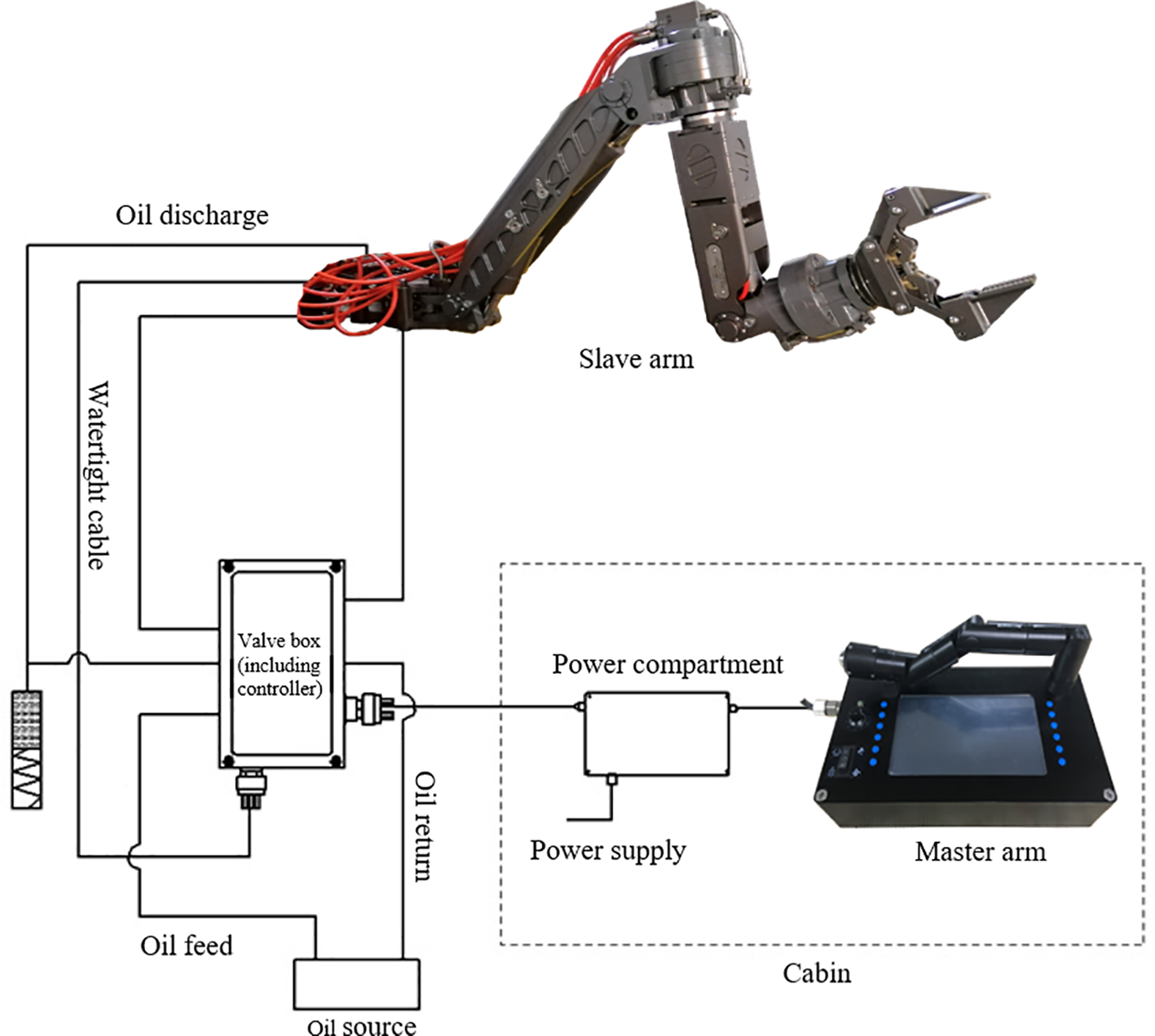
System connection diagram.
Table 3
| Parameters | Performance |
|---|---|
| Maximum reach | 1.6m |
| Full-extension maximum holding weight (in the air) | 100kg |
| Working water depth | 11000m |
| Number of functions | Seven-functions |
| Angle sensor | Closed-loop control for angular position |
| Control method | Master-slave Closed-loop control |
| Hydraulic system | Proportional valve + Hydraulic cylinder/Motor |
Specifications of the full ocean depth heavy-duty seven-function manipulator system.
In the high-pressure environment, the viscosity of the hydraulic oil will increase, resulting in poor oil-passing capacity. Excessive wear along the way will cause an insufficient oil supply for the three joints at the end of the manipulator. We divide the seven-function valve box into two. The external four-function valve box drives the four actuators of the manipulator. The other three-function valve box is integrated and embedded in the forearm arm, as shown in Figure 3. The oil source is introduced into the forearm through the elbow joint to supply oil to the wrist cylinder, the wrist motor, and the claw cylinder.
Figure 3
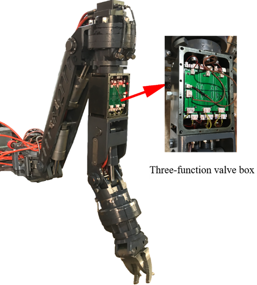
Integrated three-function valve box.
3.1 Elbow joint design
Due to the limitation of the size of the elbow joint, the original 4,500-meter hydraulic manipulator has a maximum diameter of 2.5mm and cannot be increased, as shown in Figure 4. When high-pressure and high-viscosity hydraulic oil passes through these tiny holes, great pressure loss will cause. Insufficient hydraulic oil flow cannot meet the oil demand for the end three joints. The movement of the oil cylinder will cause slow movement, stuttering, weak lifting of the wrist oil cylinder, inability to open the claws, noise, and vibration of the motor, which will cause inconvenience to the operation of the manipulator.
Figure 4
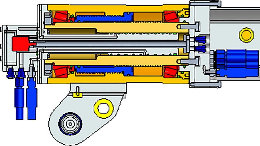
4500 meters manipulator elbow joint distribution hole.
We designed the structure of the elbow joint to improve the performance of the elbow joint to operate normally in a depth of 11,000 meters, as shown in Figure 5. We integrate the control valves of the three joints of the wrist cylinder, wrist motor, and claw cylinder of the manipulator into the forearm. The elbow joint motor only needs a set of distribution holes, so that the size of the distribution holes inside can be increased from the original 2.5mm to 5mm.
Figure 5
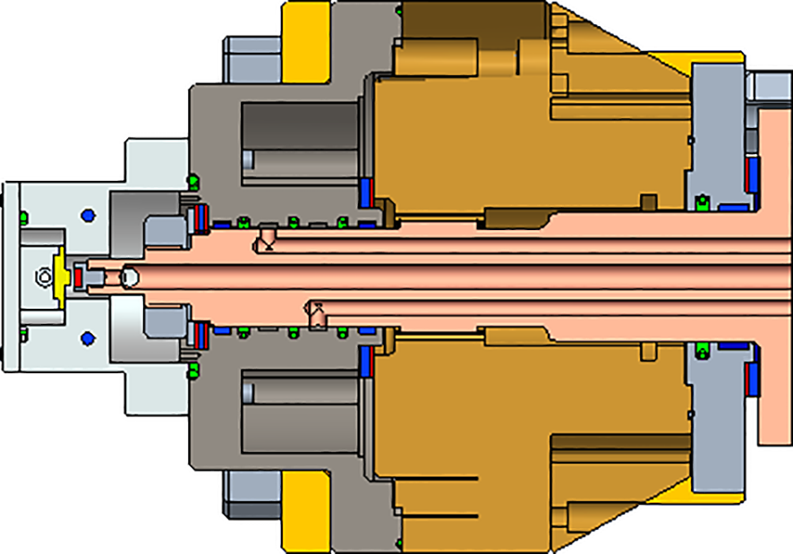
Large diameter elbow joint orifice.
3.2 Wrist joint design
The wrist joint of the manipulator is the most integrated part of the whole manipulator. It has the dual functions of realizing 360° rotation of the wrist and opening or closing the gripper. And its size is the smallest compared with other joints. As the end of the actuator, it needs to take into account the flexibility, reliability, and interchangeability of multiple types of grippers. We complete and reform the ordinary plunger hydraulic motor to make it have the functions of current distribution, power distribution, and angle detection. The modified motor has the characteristics of the compact overall structure, corrosion resistance, and high-pressure resistance, as shown in Figure 6. It becomes a low-speed, high-torque swing hydraulic motor suitable for deep-sea operations.
Figure 6
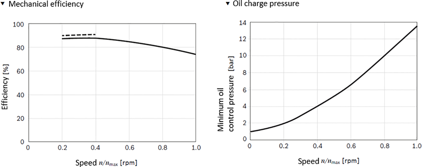
Motor performance.
The wrist joint comprises a hydraulic motor, an oil cylinder, and a claw clamp module. The structure of the wrist joint is shown in Figure 7. The hydraulic motor drives the cylinder and the claw clamp module to rotate. The claw clamp module is realized by a parallelogram mechanism driven by the cylinder. To adapt to more operating conditions, we designed two types of grippers according to the manipulator’s requirements: translational and four-finger bites, as shown in Figure 8. We can change the four-finger bite into a four-finger crossbite and a three-finger bite by adjusting the distribution of the claws. The opening of the translational claw is 140mm. The opening of the four-finger bite-type claw is 305mm.
Figure 7
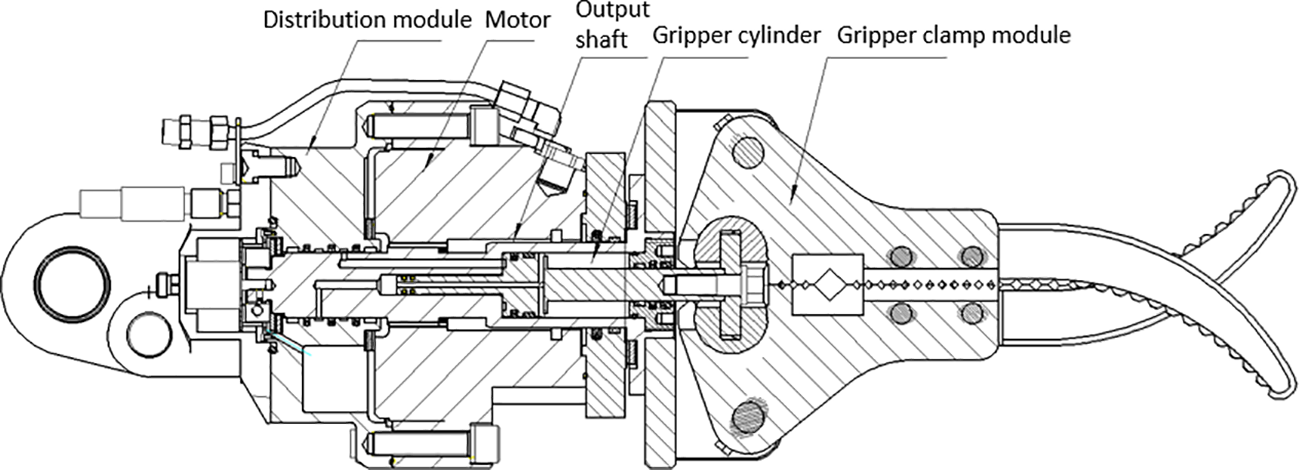
The structure of the wrist joint.
Figure 8

Claw clamp type.
3.3 Electronic control system design
The electronic control system is composed of the surface part (upper computer) and the underwater part (lower computer), as shown in Figure 9. We adopt a master-slave control method. The host computer collects sensor signals such as the angle of the master arm handle, the opening and closing of the claw, and the emergency button. After the internal single-chip microcomputer processes the signal, the command is sent to the lower computer through RS485. The lower computer receives the command to control the proportional valve and returns the working status information from the arm to the upper computer. We can realize the functions of diagnosis, parameter setting, authority management by the upper computer.
Figure 9
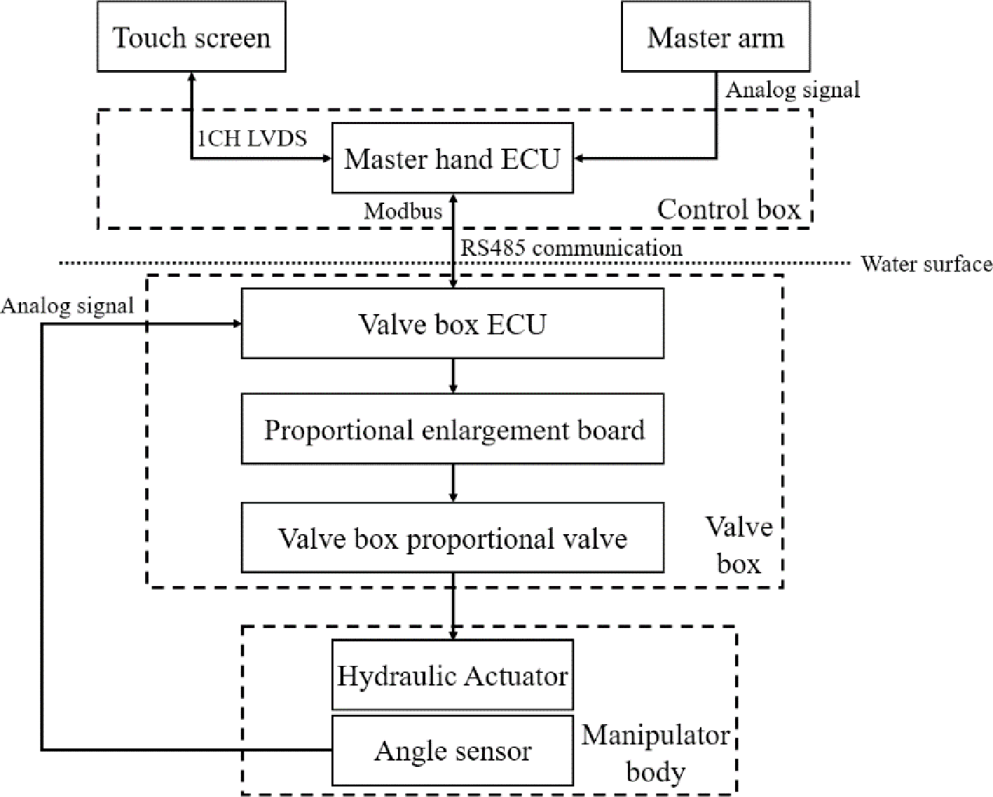
Electronic control diagram.
The valve box control system consists of three parts: motherboard, expansion board, and proportional valve control module. The motherboard is responsible for communication relay, switch valve control, water leakage detection, oil temperature detection, and working voltage and current detection functions. The expansion board expands the number of interfaces and connects more proportional valve modules. The proportional valve control module collects joint angle data and realizes closed-loop control by controlling the proportional valve. And it supports the collection of pressure data to compensate for the control parameters under different load conditions. The motherboard and the host computer are connected through RS485 to complete the command issuance and work status collection. The motherboard and the proportional valve control module realize independent networking through RS485. The proportional valve control module is shown in Figure 10.
Figure 10
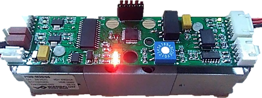
Proportional valve control module.
4 Experimental results
Load sensing technology is essential to the design of the whole sea deep manipulator, especially the load quality of the end effector of the manipulator’s claw, which directly affects the performance of the manipulator. We carry out the load condition test of the manipulator’s end effector to verify the manipulator’s control algorithm, as shown in Figure 11. Since there is no pressure sensor installed in the arm joint of the actual manipulator valve block, we let the manipulator end-effector grab a weight of 50kg. When the test wrist rotates, the manipulator grabs a 10kg cylindrical weight.
Figure 11
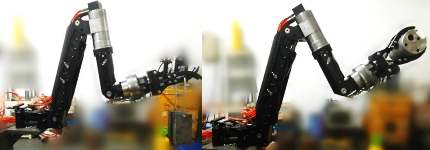
Physical view of the manipulator when grabbing 50kg and 10kg heavy objects respectively.
When testing a joint, the angle value of other joints corresponds to the maximum value of the static load. The default value of each joint is shown in the Table 4.
Table 4
| Shoulder joint | Upper arm joint | Forearm joint | Elbow joint | Wrist oscillating joint | Wrist swivel joint |
|---|---|---|---|---|---|
| 60° | 60° | 120° | 135° | 44° | 0° |
Default angle value for manipulator joint testing.
We test the following features of the system with the heavy load. The period of a given sinusoidal excitation signal is 10s, and the amplitude is determined according to the two extreme positions of each joint. The experimental curve obtained is shown in the Figure 12.
Figure 12
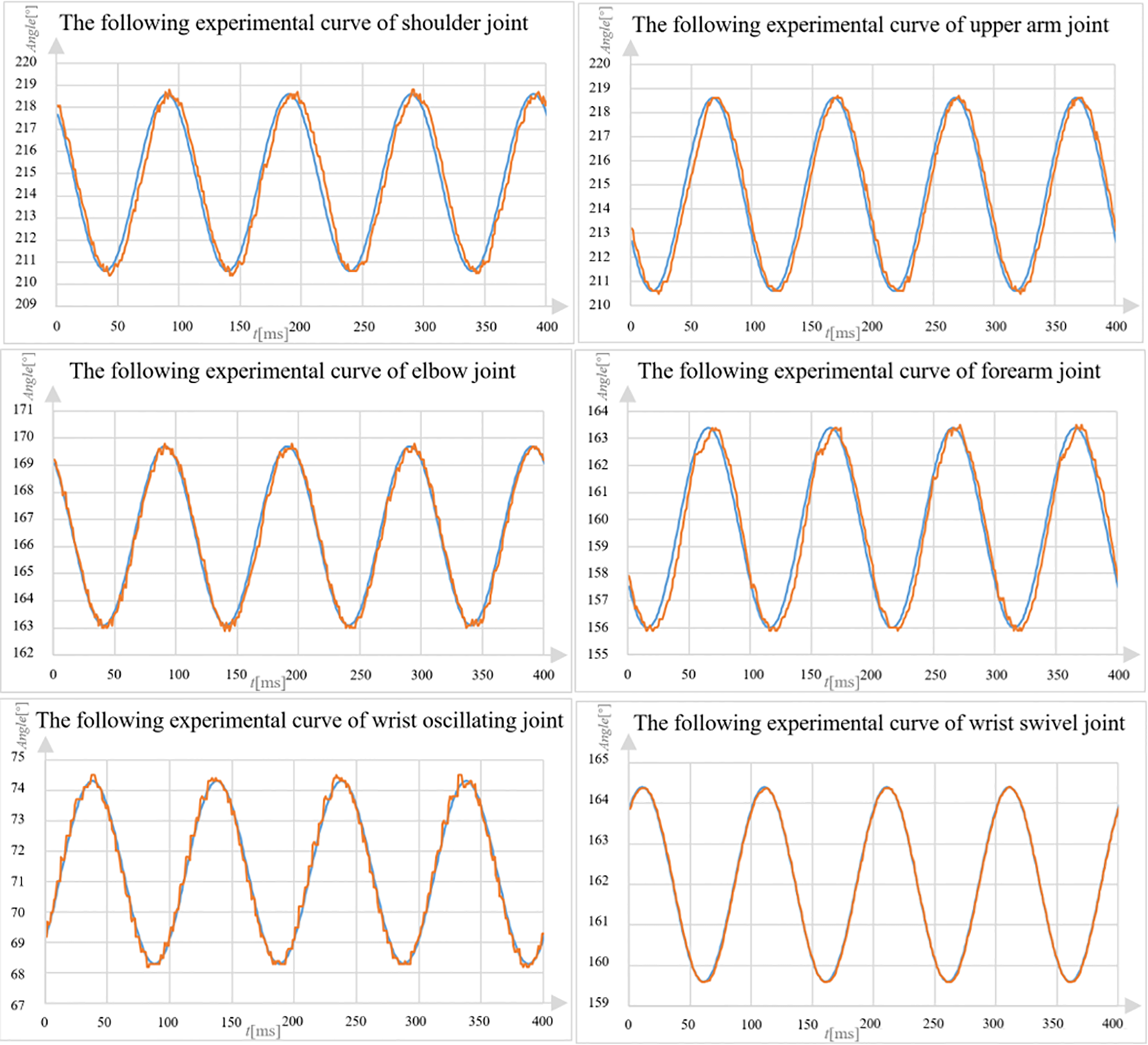
The following experimental curve of the gripper under heavy load.
According to the test data, we can get the following features of the system with the heavy load, as shown in Table 5. It shows that the system has good response consistency and tracking ability with a large range of movement.
Table 5
| Joint name | Response time/ms | Hysteresis time (sine signal)/ms |
|---|---|---|
| Shoulder joint | 0.3 | 0.5 |
| Upper arm joint | 0.4 | 0.4 |
| Forearm joint | 0.4 | 0.4 |
| Elbow joint | 0.3 | 0.2 |
| Wrist oscillating joint | 0.2 | 0.1 |
| Wrist swivel joint | 0.3 | <0.1 |
Sensing manipulator system characteristics when loaded.
To evaluate the hydraulic manipulator’s performance under high-pressure environments, a high-pressure test was conducted at a pressure of 115 MPa, as shown in Figure 13. The test involved two cycles of dynamic pressure experiments, which were monitored and recorded in real-time using video. During the experiment, the pressure in the pressure tank was gradually increased to 115 MPa at a rate of 2 MPa per minute. The manipulator’s joints were then operated every 30 minutes to assess its performance. Throughout the experiment, all aspects of the manipulator’s performance were normal, indicating that the system can function effectively at a depth of 11,000 meters. This high-pressure test provides important validation of the hydraulic manipulator’s capabilities and reliability in extreme deep-sea environments. The results demonstrate that the manipulator can perform effectively under high-pressure conditions.
Figure 13
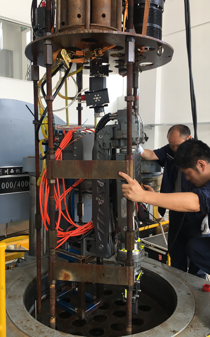
Dynamic pressure test.
5 Deployment of sea trials
On February 21, 2019, the full ocean depth heavy-duty capacity proportional hydraulic manipulator was used to carry the “Shenhaiyongshi” manned submersible for sea trials in the Southwest Pacific. The manipulator was installed on the port side of the submersible, and the team conducted three dives, designated as SY148, SY149, and SY150.
During the sea trials, the submersible and the manipulator reached a maximum depth of 3,317 meters, and the team spent a cumulative underwater time of 26 hours, as shown in Figure 14. The manipulator was able to perform various tasks, including sampling, observation, and maintenance, under extreme deep-sea conditions.
Figure 14
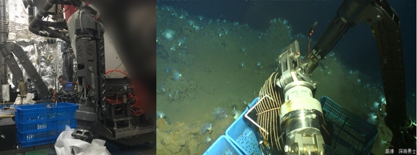
The Southwest Pacific sea trial sampling diagram of the manipulator.
The hydraulic manipulator underwent sea trials during Cruise TS21-1, which took place from August 11, 2021, to October 8, 2021, in the western Philippine Basin and the Mariana Trench. The experiment sites of Cruise TS21-1 voyage are shown in Figure 15. The sea trial involved testing the manipulator’s communication and joint movement, as well as completing engineering tasks for the “Fendouzhe” manned submersible diving. During the sea trial, the hydraulic manipulator successfully dived to a maximum depth of 10,898.8 meters and completed various tasks, including retrieving samples of rock, hairy, sea cucumber, atmospheric water, and push core. The manipulator’s communication and each joint movement were reported to be normal throughout the entire testing period. The Mariana Trench sea trial sampling diagram of the manipulator is shown in Figure 16.
Figure 15

Cruise TS21-1 voyage experiment sites.
Figure 16
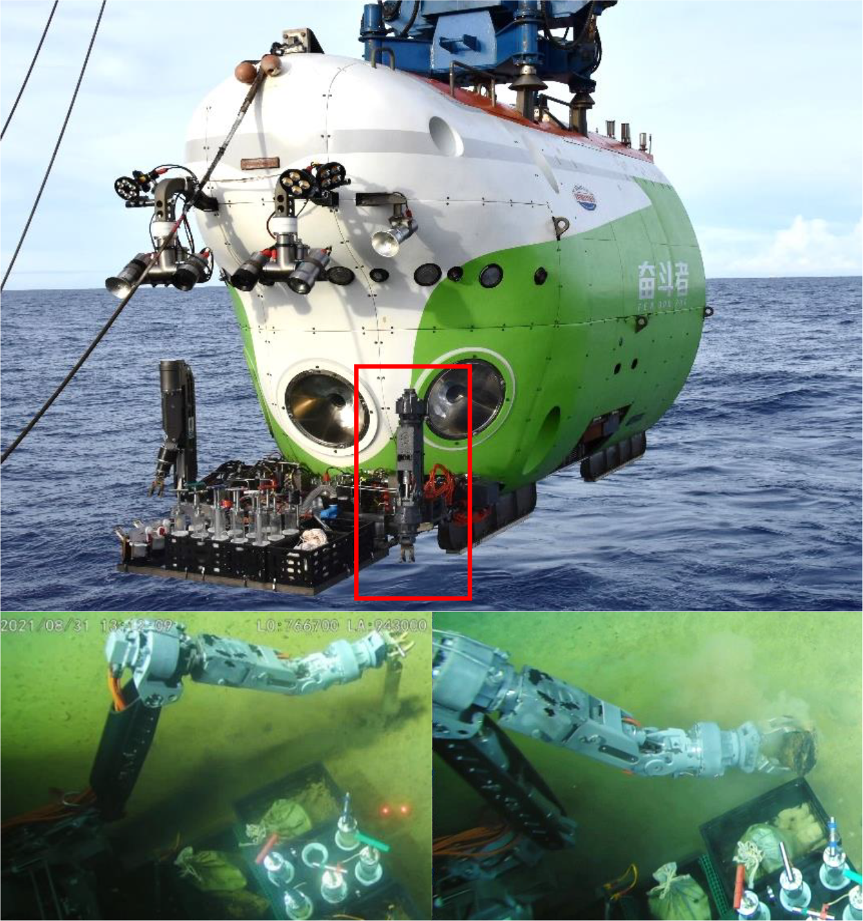
The Mariana Trench sea trial sampling diagram of the manipulator.
The successful completion of these sea trials further demonstrates the reliability and effectiveness of the hydraulic manipulator in extreme deep-sea environments. The technology has important applications in various fields, including deep-sea exploration, research, and resource development.
6 Conclusion
This paper presents the development of a full ocean depth hydraulic manipulator with heavy-duty capacity capabilities. The system design is described in detail, including both mechanical and electronic subsystems. To address challenges related to low oil-passing capacity and high loss under low temperature and high pressure conditions, the system incorporates an embedded 3-function valve box and a modified hydraulic motor. Laboratory tests were conducted to verify the performance of the hydraulic manipulator under load, and a pressure test at a depth of 11,000 meters confirmed that the manipulator is capable of functioning effectively in deep-sea environments. During Cruise TS21-1, the manipulator was carried on the manned submersible Fendouzhe and underwent a full-sea deep test, which improved the submersible’s heavy-duty operations.
Future work will focus on further research and optimization of the control algorithm for the full ocean depth hydraulic manipulator. The successful development and testing of this hydraulic manipulator with heavy-duty capacity capabilities has important applications in deep-sea exploration, research, and resource development.
Statements
Data availability statement
The original contributions presented in the study are included in the article/supplementary material. Further inquiries can be directed to the corresponding author.
Author contributions
DR: Conceptualization, Methodology, Visualization, Writing – original draft. JC: Conceptualization, Supervision, Writing – review & editing. XP: Data curation, Formal Analysis, Writing – original draft. JA: Methodology, Writing – review & editing.
Funding
The author(s) declare financial support was received for the research, authorship, and/or publication of this article. Funding for this study was provided by Key R&D Program of Zhejiang(Grant No.2024SSYS0089).
Acknowledgments
We sincerely appreciate the contribution of Zhejiang Wenhai Technology Co., Ltd. to this work, and we are also deeply grateful to to the pilots, the captain, and crews of the R/V Tansuoyihao with manned submersible Fendouzhe for their professional service during the cruises.
Conflict of interest
The authors declare that the research was conducted in the absence of any commercial or financial relationships that could be construed as a potential conflict of interest.
Publisher’s note
All claims expressed in this article are solely those of the authors and do not necessarily represent those of their affiliated organizations, or those of the publisher, the editors and the reviewers. Any product that may be evaluated in this article, or claim that may be made by its manufacturer, is not guaranteed or endorsed by the publisher.
References
1
Andrioaia D. Stan G. Pascu M. Mihaila L. (2013). Determining the shape and volume of the workSpace for the robot with parallel structure delta 3DOF using the Monte Carlo method. Appl. Mech. Mater.332, 200–205. doi: 10.4028/www.scientific.net/AMM.332.200
2
Bai Y. F. Zhang Q. F. Zhang A. Q. (2021). Modeling and optimization of compensating oil viscous power for a deep-sea electric manipulator. IEEE Access9, 13524–13531. doi: 10.1109/access.2021.3052165
3
Bhatnagar I. Kim S. K. (2010). Marine antitumor drugs: status, shortfalls, and strategies. Mar. Drugs8 (10), 2702–2720. doi: 10.3390/md8102702
4
Capocci R. Dooly G. Omerdic E. Coleman J. Newe T. Toal D. (2017). Inspection-class remotely operated vehicles-A review. J. Mar. Sci. Eng.5 (1), 13. doi: 10.3390/jmse5010013
5
Carroll A. R. Copp B. R. Davis R. A. Keyzers R. A. Prinsep M. R. (2019). Marine natural products. Nat. Prod. Rep.36, 122–173. doi: 10.1039/C8NP00092A
6
Chen Y. Z. Zhang Q. F. Feng X. S. Huo L. Q. Tian Q. Y. Du L. S. et al . (2019). Development of a full ocean depth hydraulic manipulator system. Lect. Notes Comput. Sci.11724, 250–263. doi: 10.1007/978-3-030-27535-8_24
7
Clegg A. C. Dunnigan M. W. Lane D. M. (2001). “Self-tuning position and force control of an underwater hydraulic manipulator,” in Proceedings 2001 ICRA. IEEE International Conference on Robotics and Automation (Cat. No.01CH37164). (Seoul, Korea (South)), 4, 3226–3231. doi: 10.1109/ROBOT.2001.933115
8
Corinaldesi C. (2015). New perspectives in benthic deep-sea microbial ecology. Front. Mar. Sci.2. doi: 10.3389/fmars.2015.00017
9
Deckert G. Warren P. V. Gaasterland T. Young W. G. Lenox A. L. Graham D. E. et al . (1998). The complete genome of the hyperthermophilic bacterium Aquifex aeolicus. Nature392, 353–358. doi: 10.1038/32831
10
Dong S. (2007). Direct numerical simulation of turbulent Taylor-Couette flow. J. Fluid Mech.587, 373–393. doi: 10.1017/S0022112007007367
11
Dunnigan M. W. Lane D. M. Clegg A. C. Edwards I. (1996). Hybrid position/force control of a hydraulic underwater manipulator. IEE Proc. Control Theory Appl.143, 145–151. doi: 10.1049/ip-cta:19960274
12
Flemming H. C. Wuertz S. (2019). Bacteria and archaea on Earth and their abundance in biofilms. Nat. Rev. Microbiol.17, 247–260. doi: 10.1038/s41579-019-0158-9
13
Haefner B. (2003). Drugs from the deep: marine natural products as drug candidates. Drug Discovery Today8, 536–544. doi: 10.1016/S1359-6446(03)02713-2
14
Hu G. P. Yuan J. Sun L. She Z. G. Wu J. H. Lan X. J. et al . (2011). Statistical research on marine natural products based on data obtained between 1985 and 2008. Mar. Drugs9, 514–525. doi: 10.3390/md9040514
15
Hydro Lek (2011). Available online at: http://www.hydro-lek.com/ (Accessed June 21, 2024).
16
ISE Ltd (2011). Available online at: https://ise.bc.ca/ (Accessed June 25 2024).
17
Jamieson A. (2015). Microbes, protists, and worms. 1st ed. (UK: Aberdeen).
18
Jones D. O. B. (2009). Using existing industrial remotely operated vehicles for deep-sea science. Zool. Scr.38, 41–47. doi: 10.1111/j.1463-6409.2007.00315.x
19
Jorgensen B. B. Boetius A. (2007). Feast and famine - microbial life in the deep-sea bed. Nat. Rev. Microbiol.5, 770–781. doi: 10.1038/nrmicro1745
20
Khalifa S. A. M. Elias N. Farag M. A. Chen L. Saeed A. Hegazy M. E. F. et al . (2019). Marine natural products: A source of novel anticancer drugs. Mar. Drugs17, (9). doi: 10.3390/md17090491
21
Kim B. R. Shin J. Guevarra R. B. Lee J. H. Kim D. W. Seol K. H. et al . (2017). Deciphering diversity indices for a better understanding of microbial communities. J. Microbiol. Biotechnol.27 (12), 2089–2093. doi: 10.4014/jmb.1709.09027
22
Kurumaya S. Phillips B. T. Becker K. P. Rosen M. H. Gruber D. F. Galloway K. C. et al . (2018). A modular soft robotic wrist for underwater manipulation. Soft Robot.5, 399–409. doi: 10.1089/soro.2017.0097
23
Li G. R. Chen X. P. Zhou F. H. Liang Y. M. Xiao Y. H. Cao X. et al . (2021). Self-powered soft robot in the Mariana Trench. Nature591, (7848). doi: 10.1038/s41586-020-03153-z
24
Li Y. P. Jiao Z. X. Yu T. Shang Y. X. (2020). Viscous loss analysis of the flooded electro-hydrostatic actuator motor under laminar and turbulent flow states. Processes8 (8), 975. doi: 10.3390/pr8080975
25
Lichota A. Gwozdzinski K. (2018). Anticancer activity of natural compounds from plant and marine environment. Int. J. Mol. Sci.19, (11). doi: 10.3390/ijms19113533
26
Luo G. S. Chen J. W. Gu L. Y. (2014). Research on a nonlinear robust adaptive control method of the elbow joint of a seven-function hydraulic manipulator based on double-screw-pair transmission. Math. Probl. Eng.2014 (1), 184968. doi: 10.1155/2014/184968
27
Meadows P. S. Campbell J. I. Meadows P. S. Campbell J. I. (1988). An introduction to marine science. 1st ed. (Dordrecht: Springer).
28
Orcutt B. N. Sylvan J. B. Knab N. J. Edwards K. J. (2011). Microbial Ecology of the Dark Ocean above, at, and below the Seafloor. Microbiol. Mol. Biol. Rev.75, (2). doi: 10.1128/mmbr.00039-10
29
Ramirez-Llodra E. Brandt A. Danovaro R. De Mol B. Escobar E. German C. R. et al . (2010). Deep, diverse, and definitely different: unique attributes of the world’s largest ecosystem. Biogeosciences7, (9). doi: 10.5194/bg-7-2851-2010
30
Russo P. Del Bufalo A. Fini M. (2015). Deep sea as a source of novel-anticancer drugs: update on discovery and preclinical/clinical evaluation in a systems medicine perspective. Excli J.14, 1294–1296. doi: 10.17179/excli2015-632
31
Schilling Robotics (2011). Available online at: https://www.technipfmc.com/en/what-we-do/subsea/robotics/ (Accessed June 25 2024).
32
Sivcev S. Coleman J. Omerdic E. Dooly G. Toal D. (2018). Underwater manipulators: A review. Ocean Eng.163, 431–450. doi: 10.1016/j.oceaneng.2018.06.018
33
Skropeta D. (2008). Deep-sea natural products. Nat. Prod. Rep.25, (6). doi: 10.1039/b808743a
34
Skropeta D. Wei L. Q. (2014). Recent advances in deep-sea natural products. Nat. Prod. Rep.31, (8). doi: 10.1039/c3np70118b
35
Thornburg C. C. Zabriskie T. M. McPhail K. L. (2010). Deep-sea hydrothermal vents: potential hot spots for natural products discovery? J. Nat. Prod.73, 489–499. doi: 10.1021/np900662k
36
Thurman H. V. (1996). Essentials of oceanography. fifth ed (Columbus: Merrill Pub. Co.).
37
Wynn R. B. Huvenne V. A. I. Le Bas T. P. Murton B. J. Connelly D. P. Bett B. J. et al . (2014). Autonomous Underwater Vehicles (AUVs): Their past, present and future contributions to the advancement of marine geoscience. Mar. Geol.352, 451–468. doi: 10.1016/j.margeo.2014.03.012
38
Yao J. J. Wang C. J. (2012). Model reference adaptive control for a hydraulic underwater manipulator. J. Vib. Control.18, 893–902. doi: 10.1177/1077546311412993
39
Zhang F. Zhang J. H. Cheng M. Xu B. (2022). A flow-limited rate control scheme for the master-slave hydraulic manipulator. IEEE Trans. Ind. Electron.69 (5), 4988–4998. doi: 10.1109/tie.2021.3084175
40
Zhang Q. F. Chen J. Huo L. Q. Sun B. Zhao Y. Shengguo C. (2013). Design and Experiments of a Deep-sea Hydraulic Manipulator System (San Diego, CA: 2013 OCEANS - San Diego) pp. 1–5. doi: 10.23919/OCEANS.2013.6741325
41
Zhang Q. F. Zhang Y. X. Huo L. Q. Kong F. D. Du L. S. Cui S. G. et al . (2014). Design and pressure experiments of a deep-sea hydraulic manipulator system. Lect. Notes Comput. Sci.8917, 117–128. doi: 10.1007/978-3-319-13966-1_12
42
Zhang Y. Zhang Q. Zhang A. Cui S. Du L. Huo L. (2016). Experiment Research on Control Performance for the Actuators of a Deep-sea Hydraulic Manipulator (Monterey, CA, USA: OCEANS 2016 MTS/IEEE Monterey) pp. 1–6. doi: 10.1109/OCEANS.2016.7761100
Summary
Keywords
full ocean depth, manipulator, heavy-duty, sea trial, underwater task
Citation
Ruan D, Chen J, Peng X and Ai J (2024) Development of a full ocean depth hydraulic manipulator with heavy-duty capacity. Front. Mar. Sci. 11:1470361. doi: 10.3389/fmars.2024.1470361
Received
25 July 2024
Accepted
16 September 2024
Published
15 October 2024
Volume
11 - 2024
Edited by
Yaoyao Wang, Nanjing University of Aeronautics and Astronautics, China
Reviewed by
Gaosheng Luo, Shanghai Ocean University, China
Wang Zhaoqiang, Shanghai Teacher Training Center, China
Updates
Copyright
© 2024 Ruan, Chen, Peng and Ai.
This is an open-access article distributed under the terms of the Creative Commons Attribution License (CC BY). The use, distribution or reproduction in other forums is permitted, provided the original author(s) and the copyright owner(s) are credited and that the original publication in this journal is cited, in accordance with accepted academic practice. No use, distribution or reproduction is permitted which does not comply with these terms.
*Correspondence: Jiawang Chen, arwang@zju.edu.cn
Disclaimer
All claims expressed in this article are solely those of the authors and do not necessarily represent those of their affiliated organizations, or those of the publisher, the editors and the reviewers. Any product that may be evaluated in this article or claim that may be made by its manufacturer is not guaranteed or endorsed by the publisher.