- 1Institute of Marine Science and Technology, Shandong University, Qingdao, China
- 2College of Oceanic and Atmospheric Sciences, Ocean University of China, Qingdao, China
- 3Shandong Provincial Key Laboratory of Marine Environment and Geological Engineering, Ocean University of China, Qingdao, China
The seabed surface is an important boundary for ocean exploration and foundation for ocean engineering construction. Accurate acquisition of seabed sediment mechanical properties and environmental parameters is critical to the development of marine resources and marine engineering. In this study, by designing the Seabed Cone Penetration Test (CPT) and Sampling System, multiparameter in situ testing and low-disturbance sampling of 3,000-m deep-sea seabed sediments are performed. Accounting for the stable penetration speed of the probe rod is the basis for ensuring the accuracy of the static penetration test results. The system adopts electrohydraulic proportional position control and a fuzzy proportional integral derivative (PID) controller to precisely control the position of the piston of the hydraulic circuit, which can improve the accuracy of the cone test data and reduce the interference of the sampling tube with the original sediment during the sampling process. Moreover, electrohydraulic co-simulation of the hydraulic control system was conducted with the AMESim and Simulink software, and the position control and speed control effects of the system were verified. The entire system was tested on site in the Shenhu Sea area of the South China Sea. This test successfully obtained nine in situ parameters, including physical and chemical parameters, for sediments within a depth range of 2.66 m on the seabed surface at a depth of 1,820 m. This system accurately and efficiently reflects the property characteristics of seafloor sediments in an in situ environment and can be widely used in marine engineering geological investigations.
1 Introduction
With the development and utilization of marine resources, seabed exploration and energy development have moved from the shallow sea to the deep sea, and an increasing number of marine projects have correspondingly been completed (Gubon, 1994; Leng et al., 2021; Liu and Li, 2021). In such projects, it is highly important to accurately determine the mechanical properties and environmental parameters of seabed sediments to enable the exploitation of marine mineral resources and construction of offshore engineering structures (Randolph, 2012; Cheng et al., 2018; Liu et al., 2022, 2023). There are two common methods used to measure the engineering mechanical properties of seafloor sediments: the first is to collect sediment samples from the seafloor and conduct laboratory analysis to determine their mechanical properties (Luo et al., 2016; Li and Chen, 2023); the second is in situ testing of the mechanical properties of seafloor sediments (Best et al., 1998; Zou and Kan, 2011). The experiment in the laboratory utilizing seafloor sediment sample is an effective traditional test method for studying the engineering properties of foundation sediment bodies. However, these methods have several problems, such as tedious measurement and distortion of test results, which cannot accurately reflect the real mechanical properties of the sediment body (Krage et al., 2014; Ganju et al., 2017). In situ testing is the direct mechanical testing of sediment in an in situ environment and includes methods such as penetration testing, shear testing, and other mechanical tests. Through the analysis of the mechanical test results, the mechanical properties of the sediment are obtained, which offers the advantages of rapid testing and small disturbance to the sediment layer, and the test results can better reflect the original state. Among them, the cone penetration test is the most commonly used in situ testing method. The technology works by pressing the probe installed with mechanics sensors into the seafloor sediment at a constant rate (the rate range is 0.02 m/s ± 10% according to the industry) and recording the cone tip resistance, side friction resistance, and pore water pressure with penetration depth (Yoshimura, 2013; Robertson, 2016). The seabed CPT equipment driven by the hydraulic penetration system is an important equipment for in situ detection of seabed sediment. The seabed penetration platform is lowered to the seabed through the photoelectric composite cable of vessel. The seabed penetration platform stably sits on the seabed and relies on its own weight to provide support and reaction forces. Then, the probe rod and probe are uniformly pressed into the sediment through a hydraulic drive. Because of the small diameter and high measurement range of the probe, precise measurement can be achieved for hard sediment layers such as sandy sediment and silty sediment. When the sediment is soft sediment, cone penetration test is difficult to accurately measure. Cone penetration test technology is now widely used in marine engineering geological exploration.
Four well-known companies, Fugro, Geomil, A.P. van den Berg in the Netherlands, and Datem in England, are leaders in researching marine static sounding technology (Seifert et al., 2008; Lunne, 2012; Lu et al., 2020). In 1965, the Dutch company Fugro developed the first underwater jack-up platform, CPT, denoted SEABULL. A MANTA-200 seabed CPT was produced by Geomil. The ROSON series seabed CPT produced by the company A.P. van den Berg began production in 1981. Datem, a British company, developed the Neptune series of CPT equipment in 2000.
In 2001, the drilling cone penetration test equipment developed by the Guangzhou Marine Geological Survey was the first hydraulic drive CPT equipment in China. In 2014, the CPT equipment was developed by the Key Laboratory of Marine Environmental Geological Engineering of Shandong Province. The working water depth of the equipment reached 20 m, and the maximum sounding depth was 10 m; these data were mainly applied to marine geological surveys in shallow coastal waters. In 2015, the Ocean University of China developed the SEEGeo equipment, a complex deep-sea engineering geology in situ long-term observation equipment, to carry out in situ long-term observations of ocean engineering geology (Ji et al., 2016). The Pene Vector-II seabed CPT was developed by Wuhan Panso Geological Prospecting Technology Co., Ltd (Zhang et al., 2022).
At present, the seabed CPT equipment mainly adopts hydraulic drive and hydraulic control technology to achieve uniform penetration of the probe rod. The power source is a key component of underwater equipment and provides energy and power to the mechanical system, such that many complex functions of underwater operation equipment can operate normally. Hydraulic drives offer many advantages, such as a high power-to-mass ratio, a compact structure, high reliability, and stepless speed regulation over a large range. Therefore, hydraulic drives have been widely used in underwater operation equipment (Chen et al., 2010; Luo and Zhang, 2011). The control technologies for underwater hydraulic systems can be divided into switch control, electrohydraulic proportional control, and electrohydraulic servo control (Xue et al., 2021). The seabed CPT equipment, such as CPTss and SEEGeo, penetrates the probe rod through a hydraulic drive and controls the motion process of the hydraulic cylinder through the electromagnetic on–off valve. The traditional on–off valve-controlled hydraulic system can only make the piston rod move to a predetermined position and cannot accurately control the speed of the piston rod. This hydraulic control system cannot overcome the influence of load changes on the penetration velocity effectively, and the ability to resist load disturbances is poor, which affects the accuracy of in situ tests. The Pene Vector-II equipment adopts an electrohydraulic proportional speed regulating valve to control the platform’s penetration speed and introduces the fuzzy proportional integral derivative (PID) algorithm in the control to achieve a uniform and stable penetration speed of the probe pole under complex geological conditions and improve the accuracy of static contact detection test data (Zhang et al., 2022). The problems, such as poor speed stability and weak load disturbance rejection performance of the actuator in the hydraulic penetration system, are common in the working process of seabed CPT equipment.
This study investigates the Seabed Cone Penetration Test and Sampling System; analyzes and designs a corresponding mechanical structure, hydraulic transmission, and speed control strategy for the hydraulic penetration platform; and demonstrates multiparameter in situ testing and low-disturbance sampling of 3,000-m-deep seabed sediments. The recordings are shown to accurately and efficiently reflect the characteristics of seabed sediments under in situ environmental conditions. First, a multifunctional and highly integrated penetration platform is designed from the structural form and driving mode to ensure the efficient and stable operation of the system in a complex marine environment. Then, a hydraulic control system under electrohydraulic proportional position control and fuzzy PID control is designed to improve the stability, rapidity, and accuracy of the hydraulic penetration system. The motion robustness and stability of the control scheme are discussed. It can be concluded that the fuzzy adaptive PID control scheme can effectively reduce the influence of variable loads on the penetration velocity, so as to ensure the stability of the penetration velocity under complex geological conditions. Finally, in situ tests were carried out in the Shenhu Sea area of the South China Sea from the research ship “Ocean Geology No. 9”.
2 Materials and methods
2.1 Introduction of the Seabed Cone Penetration Test and Sampling System
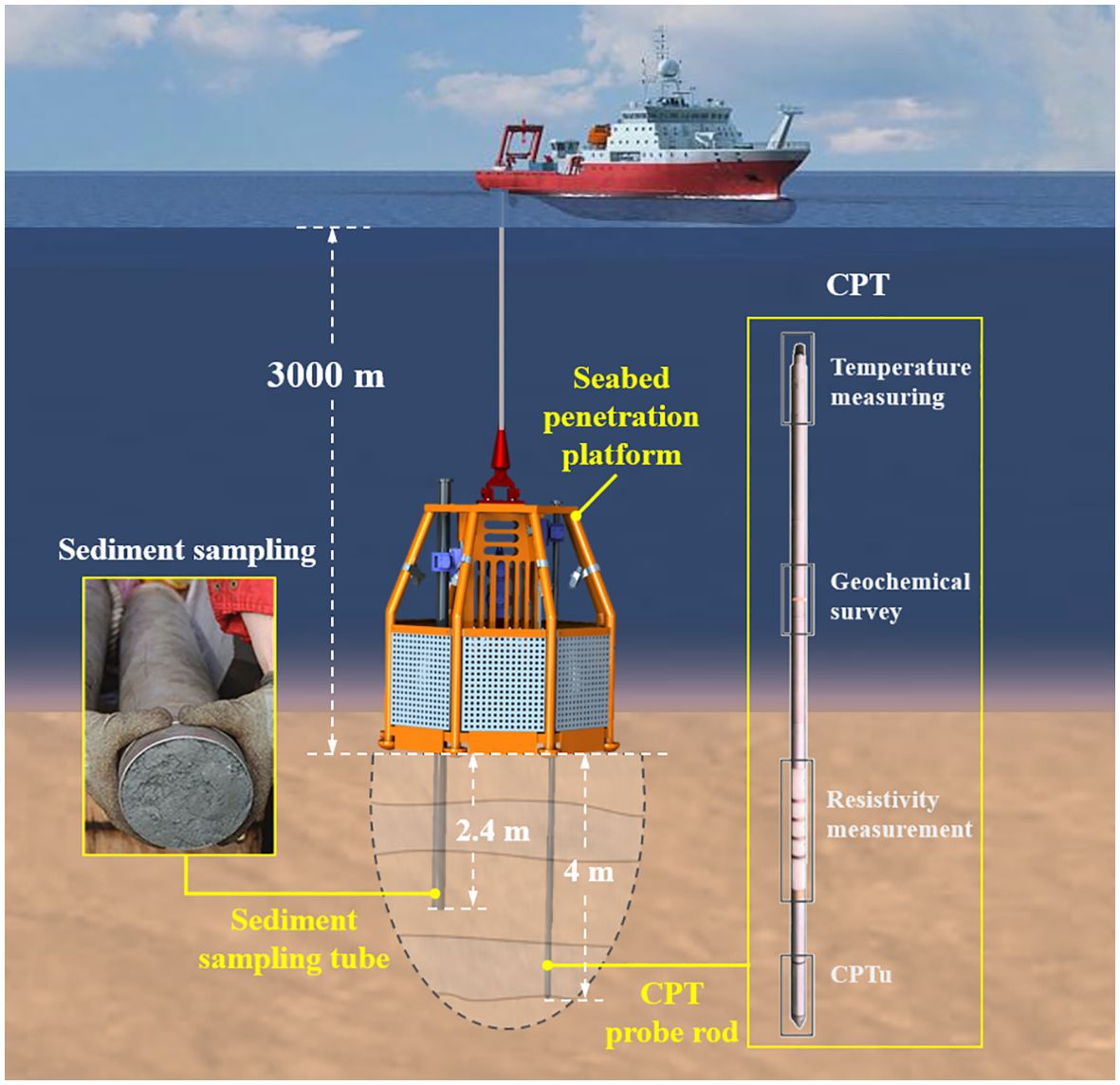
The Seabed Cone Penetration Test and Sampling System combines the traditional cone penetration test with low-disturbance sampling techniques to accurately determine the mechanical properties of sediments and master the engineering properties of seabed sediment. The primary technical indices of this equipment are provided in Table 1, and its working principle is shown in Figure 1. The system can be divided into three parts: a seabed penetration platform, a CPT probe rod, and a sampling tube. These parts are described in detail as follows:
1. The seabed penetration platform, as the vessel of the system, is used to carry the CPT probe rod and sampling tube. It achieves constant and stable penetration and withdrawal of the probe rod and sampling tube. Structural design was carried out on the penetration module, and static analysis was conducted on key components. At the same time, the hydraulic system has also been designed. A highly integrated carrier platform with reasonable structural strength and component quality layout is designed to ensure smooth and reliable operation of the platform on the seabed.
2. The CPT probe rod is an extension of conventional cone penetration test technology. A CPT probe, a resistivity sensor, a temperature sensor, and a multiparameter geochemical sensor are integrated on the probe rod, which can measure nine parameters in situ, including the physical, chemical, and mechanical parameters of sediments (Cui et al., 2023). Thus, this approach can accurately and efficiently reflect the property characteristics of seafloor sediments under in situ environmental conditions.
3. A sediment sampling tube is used to obtain sediment column samples. Through laboratory sediment tests, the sediment particle composition is analyzed to obtain stratigraphic and structural data in the investigation area. The results of the laboratory sediment sample analysis and the CPT in situ test are also able to be supplemented and corrected by each other.
2.1.1 Mechanical structure design of the seabed penetration platform
The seabed penetration platform is the underwater carrier of the whole system. Based on its main functional characteristics, the structural form and driving mode of the platform were considered. A multifunctional and highly integrated penetration platform has been designed to achieve an efficient and stable operation of the system in complex marine environments.
The seabed penetration platform adopts a hydraulic drive to realize the penetration and withdrawal of the probe rod and sampling tube. Additionally, the altimeter, attitude sensor, lighting, and camera are installed on the platform. The platform frame not only needs to provide installation and bearing space for the above instruments, but also needs to provide sufficient protection for them. To adapt the equipment to a variety of operating environments and facilitate its application in the sea, the platform frame is designed as a regular octagonal structure with two layers above and below it. The outer diameter of the bottom cross-section is Φ1.8 m, and the overall height of the equipment is 1.8 m.
The platform relies on its own weight to provide the reaction force during penetration. Therefore, equipment tilting due to insufficient dead weight or sinking deeper due to a large dead weight affects the authenticity of the measurement data. To satisfy this demand, skirt plates were installed around the base of the equipment to increase the supporting area of the equipment when it touched the seabed. Moreover, a counterweight fixing slot was designed at the bottom of the platform, where counterweight blocks were placed to increase the overall weight of the equipment and improve its stability on the seabed. Considering these design requirements, the overall structure of the seabed hydrostatic penetration platform is shown in Figure 2.
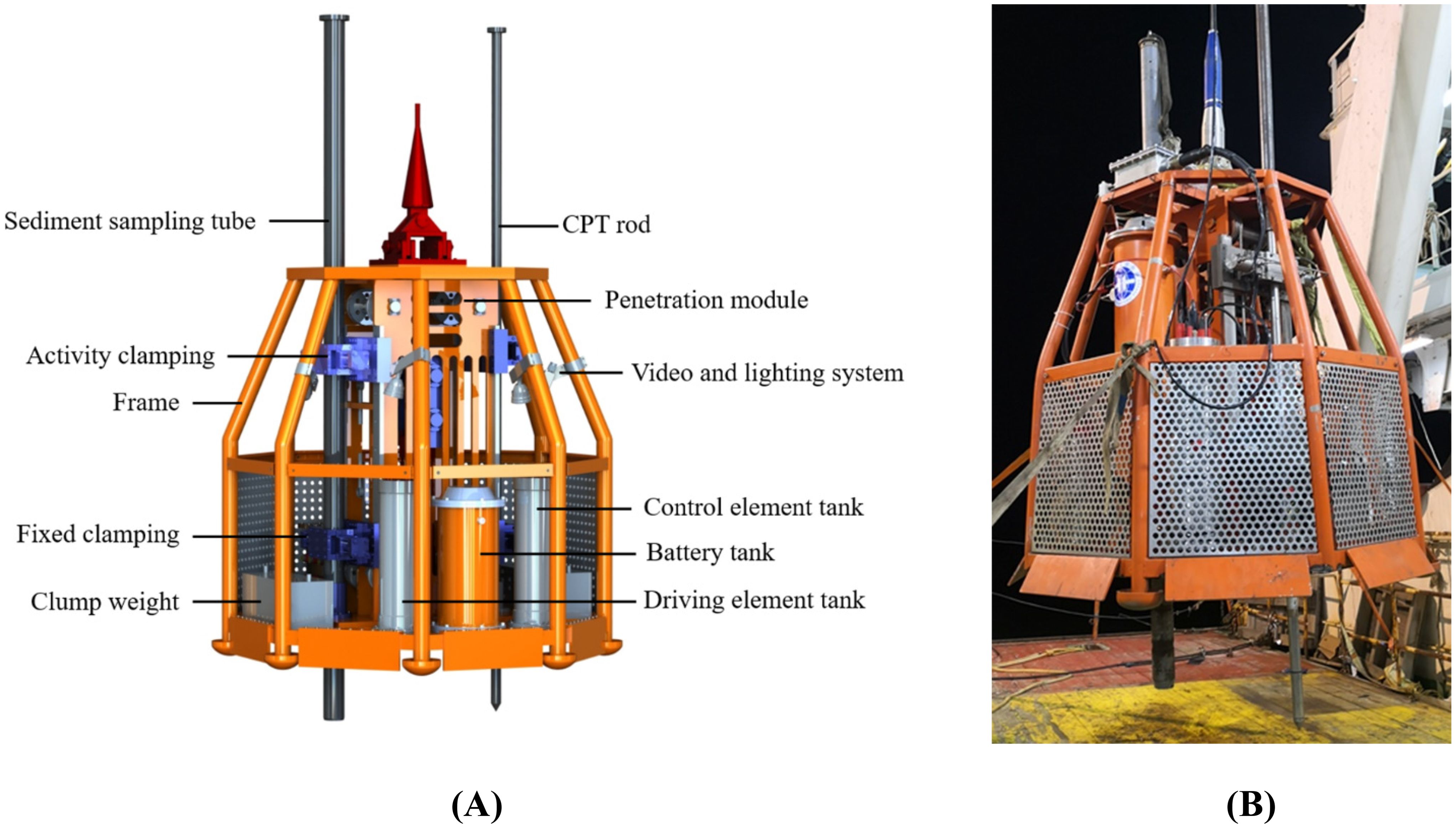
Figure 2. Seabed penetration platform: (A) Mechanical structure diagram; (B) picture of equipment used for field application.
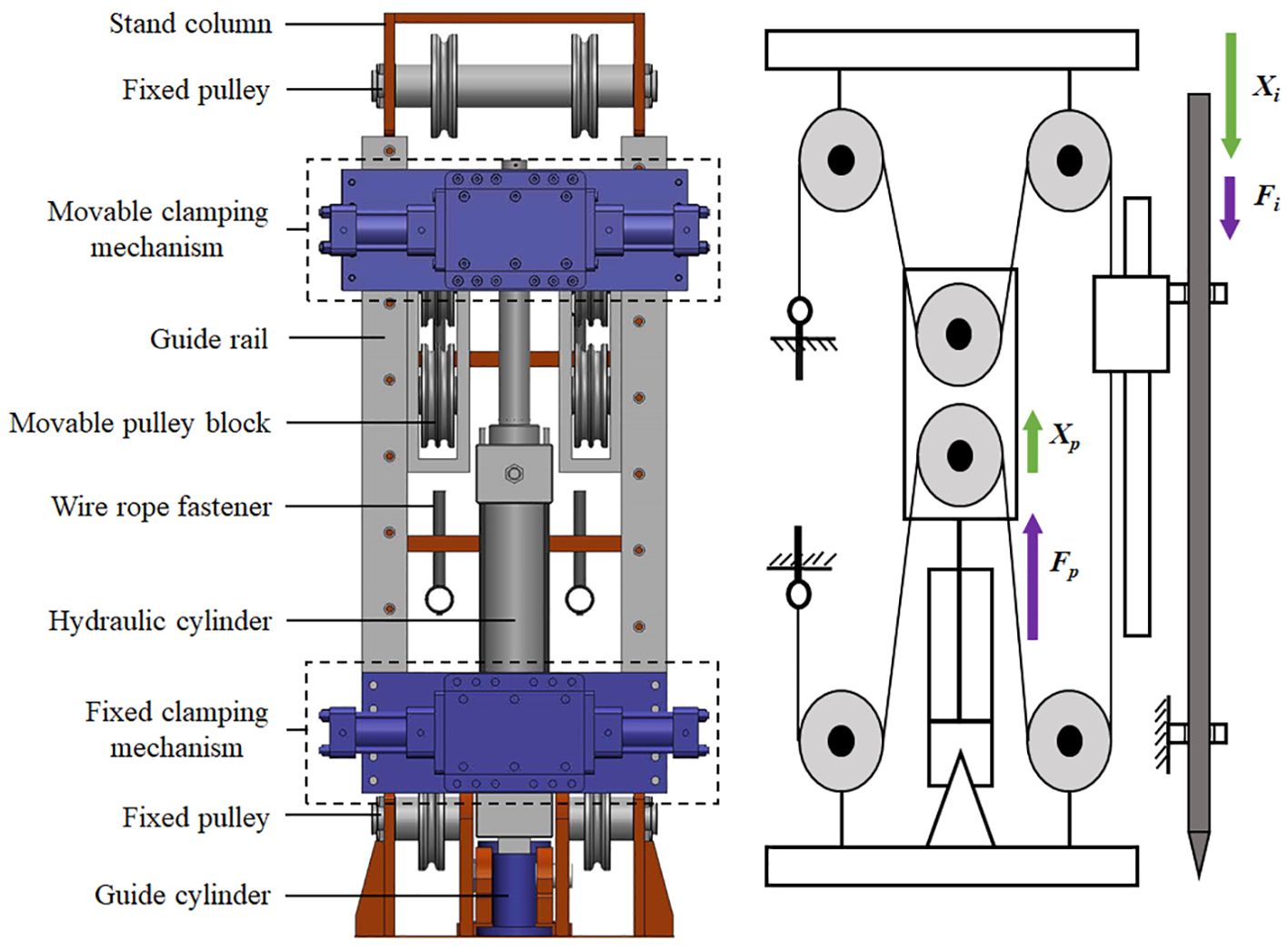
To make the whole platform more compact and realize long-distance penetration, a penetration module with a single travel distance of 0.6 m was designed. This module can achieve reciprocating motion, mainly through the use of a column, a penetrating hydraulic cylinder, a clamping mechanism, and a transmission mechanism. The penetration module was designed with a stroke amplification mechanism that utilizes synchronous steel wire ropes and pulley blocks to achieve the amplification of hydraulic cylinder stroke. The penetration side of the probe rod and the penetration side of the sampling tube were symmetrically installed on both sides of the column, corresponding to their respective transmission mechanisms and clamping mechanisms and sharing the same penetration hydraulic cylinder. The penetration module with reciprocating circulatory action and stroke amplification improves the efficiency and stability of the platform. The sediment sampling tube and probe rod are inserted in the same way, and the mechanism of penetrating module is analyzed based on the process of inserting the probe rod. Figure 3 shows the overall structure of the penetration module. The penetration force of the probe rod is half of the driving force of the hydraulic cylinder, and the single penetration stroke of the probe rod is twice the maximum stroke of the piston rod of the hydraulic cylinder. Therefore, the total stroke of the hydraulic piston rod is 0.3 m.
When the equipment inserts the probe rod into the seabed, the upper movable clamping mechanism clamps the probe rod, and the lower fixed clamping mechanism releases the probe rod. The piston rod of the penetrating hydraulic cylinder extends, and its output force and speed are transmitted by the steel wire rope and the pulley block. This steel wire rope drives the movable clamping mechanism fixed on the sliding seat to move downward together. Meanwhile, the displacement sensor in the hydraulic cylinder is used to measure the displacement of the piston rod in real time. After the completion of one penetration stroke, the lower fixed clamping mechanism clamps the probe rod, and the upper movable clamping mechanism is loosened. The piston rod of the penetrating hydraulic cylinder retracts, and the upper movable clamping mechanism returns to the initial position. The above actions are repeated to complete the penetration process.
2.1.2 Hydraulic penetration system
The working process of the penetration module has been described in detail above. The clamping hydraulic cylinder and the penetrating hydraulic cylinder are used as action actuators to realize the penetration, clamping, and pulling out of the probe rod and the sediment sampling tube.
The corresponding hydraulic principle diagram is shown in Figure 4. The hydraulic system mainly includes a DC motor, a hydraulic pump, a relief valve, an injection hydraulic cylinder, a clamping hydraulic cylinder, an accumulator, a pressure compensator, and other components. The mechanical energy of the DC motor is converted into pressure energy from the hydraulic oil through the hydraulic pump. Hydraulic oil is transported to the hydraulic cylinder through various control valves. Then, the hydraulic cylinder converts pressure energy into mechanical energy, causing the hydraulic cylinder to drive the load according to the specified action. The different uses of hydraulic cylinders can be divided into clamping mechanism hydraulic circuits and hydraulic injection circuits. Through the combination of the above two hydraulic circuits and execution actions, the cycle process of penetration and withdrawal action is realized.
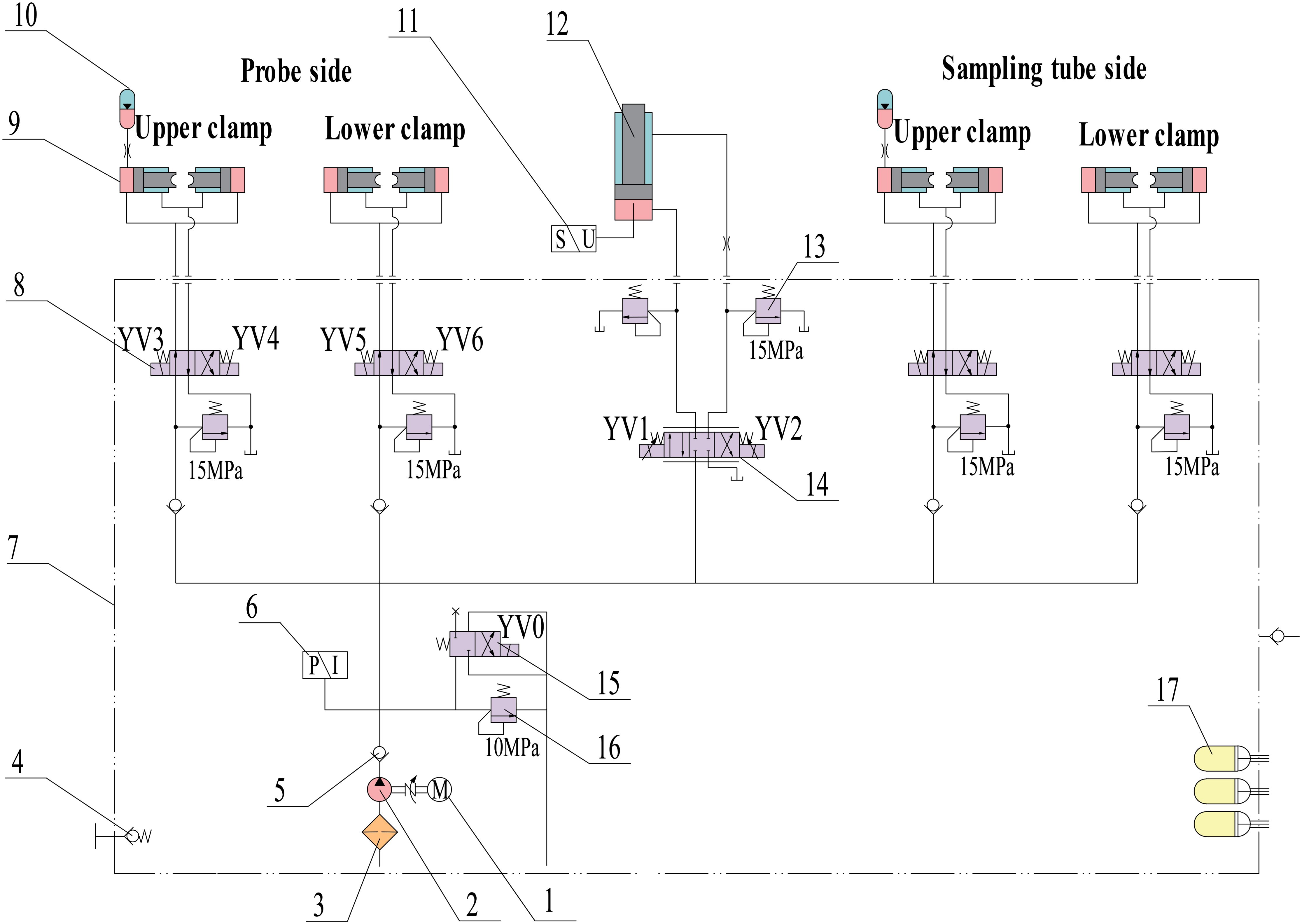
Figure 4. Hydraulic system schematic diagram. Note: 1, DC motor; 2, hydraulic pump; 3, oil filter; 4, oil valve; 5, check valve; 6, pressure sensor; 7, oil tank; 8/15, solenoid directional valve; 9, clamping hydraulic cylinder; 10, accumulator; 11, displacement sensor; 12, injection hydraulic cylinder; 13/16, relief valve; 14, proportional directional valve; 17, pressure compensator.
2.1.3 Static analysis of the key components
The underwater working environment is complex. To ensure the reliability of the platform structure, the ANSYS Workbench software was used to perform static analysis on the key components of the platform. The stand column was made of stainless steel 316 L material, and the plate was designed with weight reduction holes. The stand column structure was subjected to the tension of the wire rope and the pressure of the penetrating hydraulic cylinder. To ensure the safety and reliability of the column frame, static analysis of the stand column was needed. To simplify the model, irrelevant components such as wire ropes, pulley blocks, and wire rope tensioners were removed. Figure 5A shows this simplified model. The column model material was set as stainless steel, and the grid elements were generated by static structuring in the commercial software ANSYS. Then, the load and constraint were applied, as shown in Figure 5B, according to the actual stress situation of the column.
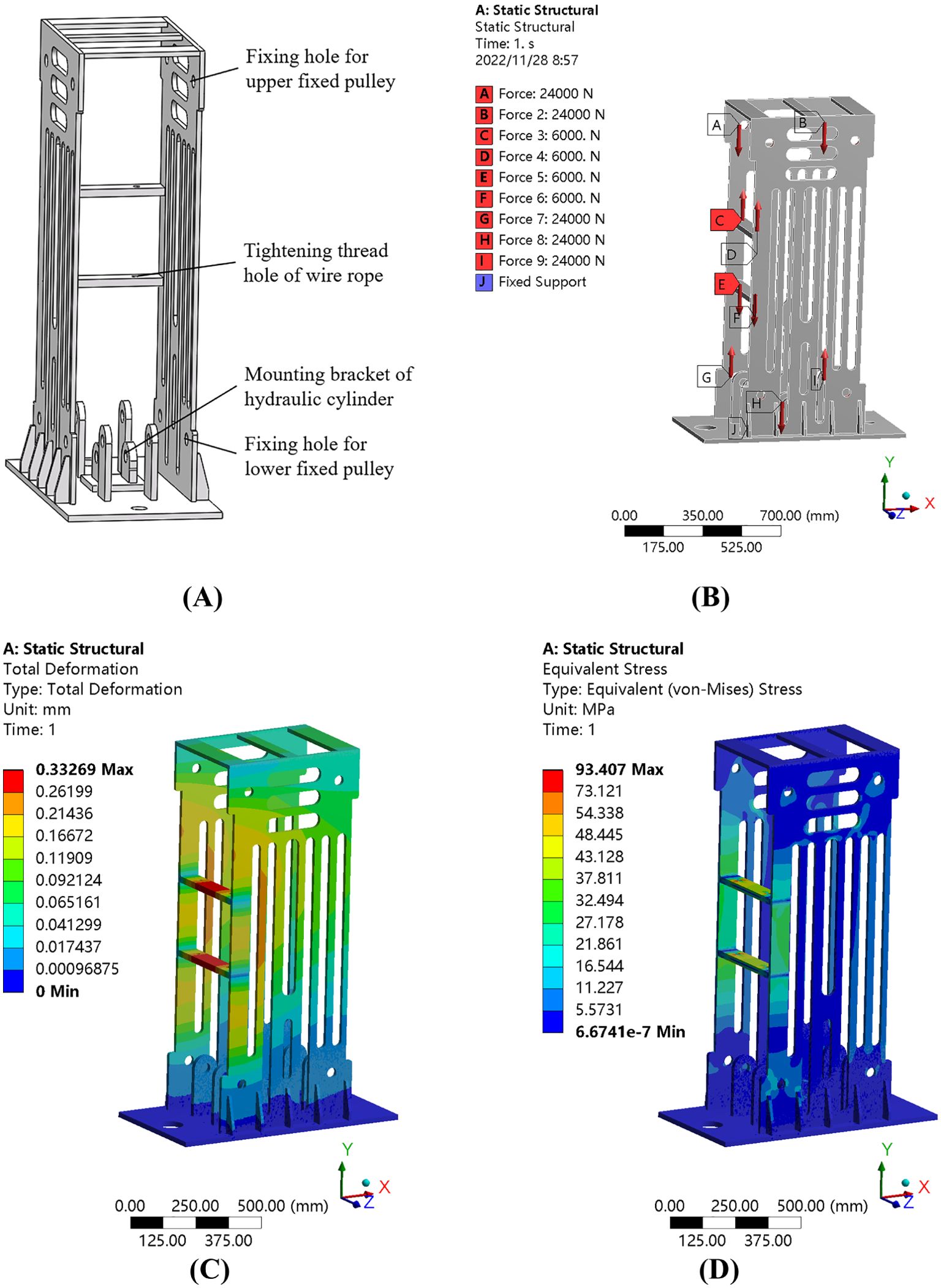
Figure 5. Static analysis of the stand column: (A) Structural diagram of the stand column. (B) Load distribution. (C) Strain distribution. (D) Stress distribution.
Through finite element simulation analysis, the stress and strain distribution law of the column was obtained for a penetration force kN. By observing the strain distribution, as shown in Figure 5C, and the stress distribution, as shown in Figure 5D, it is determined that the stand column will not fail and that the deformation meets the working requirements.
2.2 Penetration velocity stability
The penetration speed of the probe rod is an important control index of the cone penetration test. A penetration speed that is too fast, too slow, or unstable will lead to distortion of the measurement parameters. Most cone penetration test specifications at home and abroad require the probe to be pressed into the formation at a constant rate of 0.02 m/s ± 10% (Hardison, 2015). To ensure the uniformity and stability of the penetration speed of the probe rod under complex geological conditions and improve the accuracy of the static contact detection data, the hydraulic transmission system of the seabed penetration platform was studied first. The hydraulic system adopted an electrohydraulic proportional position control scheme. By utilizing the relationship between the speed and displacement, the speed of the hydraulic cylinder piston rod can be precisely controlled. Second, a fuzzy PID control method that can realize the online self-tuning of control parameters was established to effectively reduce the influence of variable loads on the penetration velocity. This method improves the control accuracy of the hydraulic system and ensures the accuracy of the seabed CPT data.
2.2.1 The proportional-valve-controlled electrohydraulic system
To ensure the stable operation of the penetration platform under the complex and harsh working environment of 3,000 m underwater, the hydraulic system adopted a proportional valve control cylinder position control scheme based on a quantitative pump. The proportional directional valve adjusts the size and direction of the output hydraulic oil flow and controls the speed and direction of the piston rod movement of the hydraulic cylinder based on throttling controls.
In the hydraulic penetration system, the actuator is the hydraulic cylinder, and the controlled object is the displaced piston rod. The displacement sensor converts the displacement signal of the piston rod into an electrical signal and feeds it back to the control system. The control system generates an error signal by comparing the feedback signal and the input signal. This error signal is driven by a proportional amplifier to control the electrohydraulic proportional directional valve. The proportional directional valve regulates the flow rate of the hydraulic injection circuit, thereby accurately controlling the position of the hydraulic cylinder piston. Based on the relation between the speed and displacement, the movement speed of the piston rod is controlled. The position closed-loop control system is shown in Figure 6.
The establishment of an accurate mathematical model is the precondition for analyzing system performance. Based on the characteristics of an asymmetric hydraulic cylinder controlled by a four-way valve, a mathematical model of the hydraulic cylinder and load was established. The motion accuracy of the penetration process was emphasized during this process, so the analysis was conducted for the case when “.” Accordingly, a mathematical model of the hydraulic cylinder and load was derived.
The flow rate equation for the three-position four-way proportional electromagnetic valve is as follows:
where is the piston rod area in the no-rod cavity of the hydraulic cylinder, is the displacement of the piston rod, is the equivalent leakage factor, is the load pressure, is the additional leakage factor, is the oil source pressure, is the equivalent total volume, and is the effective bulk elastic modulus.
When the piston is extended, the balance equation between the output force and the load force of the hydraulic cylinder is as follows:
where is the total mass of the piston and the load converted to the piston, is the viscous damping coefficient of the piston and load, is the load spring stiffness, and is the external load when the piston rod is extended.
When the spool is shifted to the right, i.e., “”, the linearized flow equation of the electrohydraulic proportional directional valve is as follows:
where is the flow gain of the valve, is the displacement of the valve core, and is the flow-pressure coefficient of the valve.
After Laplace transforms of Equations 1–3, the total output displacement of the hydraulic cylinder under the action of spool displacement and an external load can be obtained:
where
is the hydraulic natural frequency, ;
is the total flow pressure coefficient, ; and
is the hydraulic damping ratio, .
The transfer function of the total output displacement of the hydraulic cylinder to the displacement of the valve core is as follows:
The transfer function of hydraulic cylinder piston displacement of the external load force is as follows:
2.2.2 Design of the fuzzy adaptive PID controller
To improve the stability of the penetration process and reduce the influence of uncertain factors in the seabed environment on the position control accuracy of the hydraulic system, a fuzzy adaptive PID control scheme was designed. This control scheme enables the hydraulic penetration system to maintain favorable position control accuracy and anti-load disturbance performance. Fuzzy control is a nonlinear intelligent control method first proposed by Professor Zadeh for computer digital control. Its greatest advantage is that it does not need to rely on the precise mathematical model of the controlled object and has favorable anti-interference ability for adjusting the parameter changes of the object (Pedrycz, 1993; Zadeh, 1996; Chen and Pham, 2001). Figure 7 shows the structure of the fuzzy PID controller.
The traditional PID control system is based on the error between the real-time data of the controlled object and a given expected value. By performing proportional, integral, and differential function operations on the error values, the result is used to control the controlled object.
The fuzzy adaptive PID controller takes the error “” (the difference between the actual measured value and the expected value) and the error change rate “” as the input and uses fuzzy control rules to adjust the three parameters of the PID controller in real time to adjust the size of the control quantity, adapt to complex and variable load conditions, and achieve the best control effect (Carvajal et al., 2000; Hu and Ying, 2001). The calculation formula of the fuzzy PID control parameters is as follows:
where are the outputs of a conventional PID controller and are the adjustment factors of the final parameters of the fuzzy controller.
The working process of the fuzzy controller is divided into the following three steps. The first step implements the “fuzzification” process, which converts the exact input into the membership function of a fuzzy set. In the second step, the fuzzy control rules are formulated according to expert experience, and the fuzzy input values are added to a “fuzzy output” set composed of IF–THEN control rules to carry out fuzzy inference. In the third step, the precision processing of the fuzzy control quantity is the essence of obtaining the most representative and accurate control signal (Hu and Ying, 2001).
To improve the adaptability of the model to uncertain input parameters, the input and output parameters were divided into seven levels: NB, NM, NS, ZO, PS, PM, and PB. Considering the adjustment effect of the PID control parameters on the system, the fuzzy control rules shown in Table 2 are obtained.
The fuzzification process in fuzzy control is realized by a membership function. In practical engineering, triangular membership functions and Gaussian membership functions are mostly used. The expression of the triangular membership function is as follows:
where a, b, and c are coefficients of the membership function.
The expression of the Gaussian membership function is as follows:
For the membership functions of the input and output of this system, PM, PS, ZO, NS, and NM adopted a triangular membership function, and for the fuzzy sets PB and NB, a Gaussian membership function was adopted.
Because the barycenter method has smooth output inference control, the barycenter method was used to accurately process the fuzzy control quantity, and its output value could be expressed as follows:
2.3 Simulation analysis of the position control effect of the hydraulic system
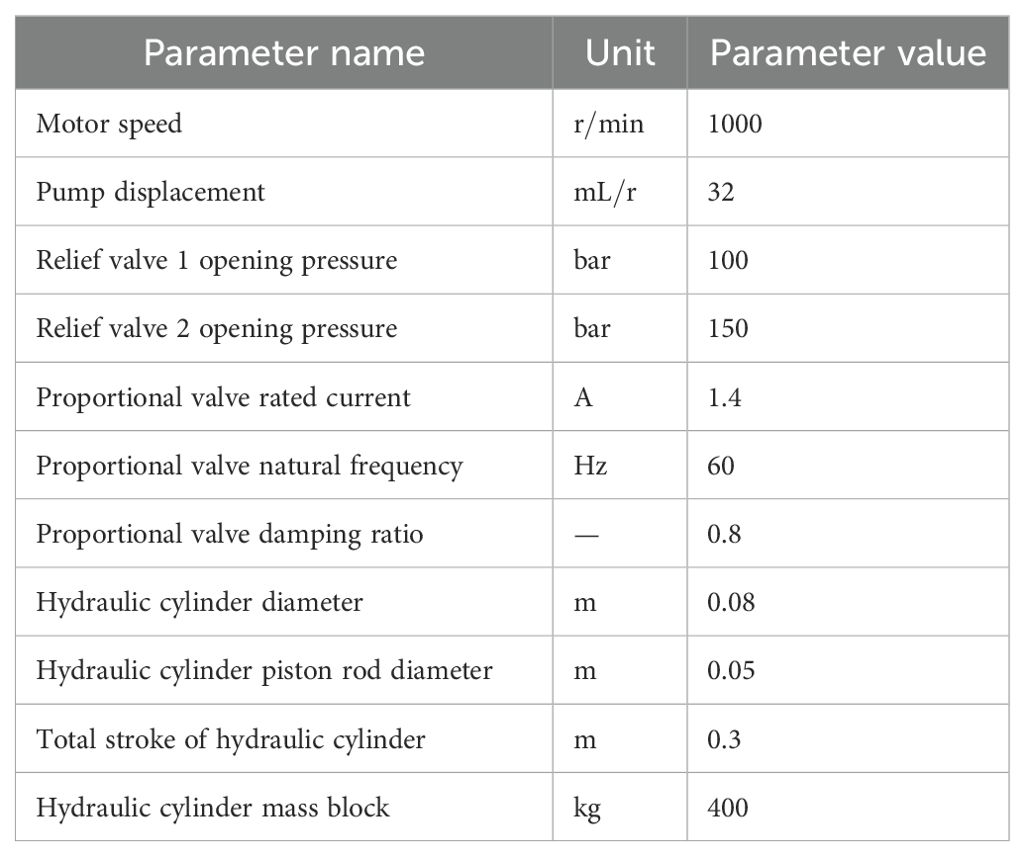
To verify the effect of system position control and velocity control, a joint simulation of an electrohydraulic proportional position control system was carried out. The AMESim software and MATLAB/Simulink software were used to construct simulation models of the hydraulic part and the control part of the electrohydraulic proportional control system. Considering the proportional valve control electrohydraulic system as an example, the integrated AMESim and Simulink model of the hydraulic penetration system based on the fuzzy adaptive PID control scheme is shown in Figure 8A. The optimal PID control parameters are obtained by using the PID Tuner controller of Simulink. The physical model of the hydraulic system built in AMESim is shown in Figure 8B, and the main parameters of the model are shown in Table 3.
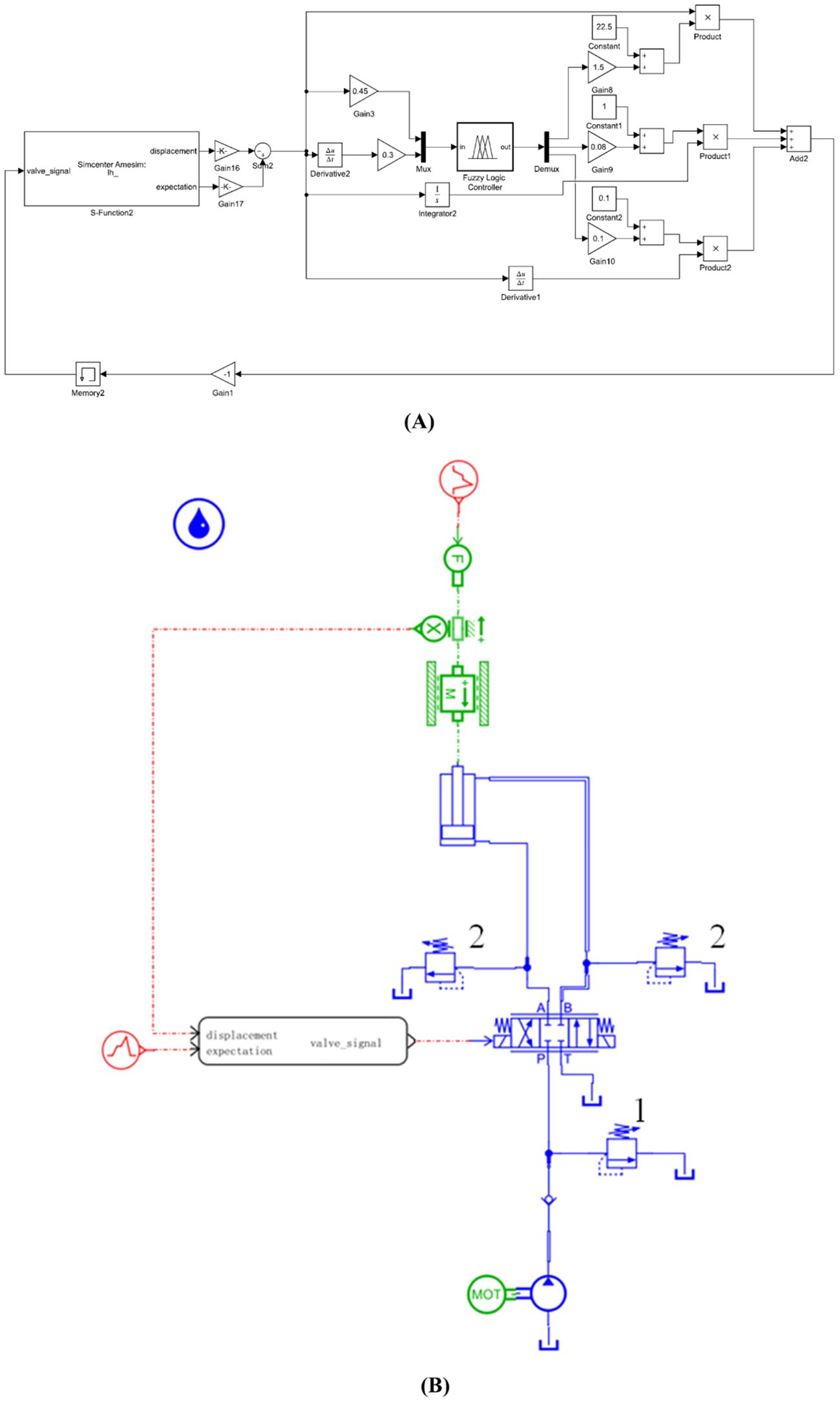
Figure 8. Simulation model: (A) Fuzzy adaptive PID control model. (B) The proportional valve-controlled hydraulic system model.
According to the working requirements of the hydraulic penetration platform, the displacement time curve of the piston rod is set in the simulation, as shown in Figure 9A. During the motion of the piston rod, an external load is applied to the piston rod to simulate the changes in resistance during penetration and withdrawal. The external load variation curve set in the AMESim hydraulic model is shown in Figure 9B.
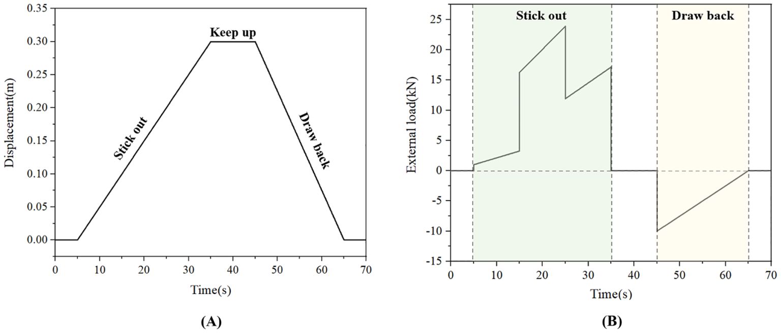
Figure 9. Input signals during simulation analysis: (A) Expected displacement curve of the piston rod. (B) External load change curve.
2.4 Field application
To validate the working performance of the Seabed Cone Penetration Testing and Sampling System, two sea tests were carried out after the assembly and commissioning of the system. The first offshore test was conducted in the sea area of Guishan Island. Through practical operation at sea, the process of equipment layout, communication control, online monitoring, and equipment recycling has been further optimized. This offshore experiment successfully evaluated the physical and chemical properties of shallow surface sediments and sediment columns in the offshore area, providing rich practical systems for enabling far-reaching marine engineering applications.
The second sea test was located in the Shenhu Sea area of the South China Sea. The bottom layer is composed of soft and mostly silty sediments. The Shenhu Sea area is located inside the Baiyun Sag in the Pearl River Estuary Basin (Wu et al., 2022). The Baiyun Sag has abundant source rocks, and the characteristics of well-developed reservoirs and structural traps endow the Baiyun Sag with favorable geological conditions for oil and gas accumulation. Therefore, there are abundant marine oil and gas resources in the slope area of the Shenhu Sea area (Li et al., 2010).
Through at-sea testing, the application of the Seabed Cone Penetration Test and Sampling System was established; this test involved a series of evaluation, inspection, and testing processes, such as system assembly and debugging; equipment layout; and system underwater in situ testing and sampling tests. To ensure the smooth progress of the experiment, it is necessary to follow reasonable offshore testing procedures and operating methods. After the scientific research ship arrived at the scheduled sea trial site, the equipment was lowered to the seabed at a constant speed through the A-shaped hanger and dedicated winch at the stern of the ship. When the inclination angle of the equipment meets the working requirements of the system, the penetration test began. The operation instructions issued by the deck control system were transmitted to the underwater equipment through the optical cable. The seabed penetration platform inserted the CPT rod and sample tube into the sediment at a constant rate. During the penetration process, in situ detection data and underwater video signals were synchronously transmitted to the deck monitoring room through the optical cable and displayed in real time on the upper computer screen. At the same time, the platform attitude, hydraulic cylinder displacement, cone tip resistance, sidewall friction, pore water pressure, temperature, and other parameters were recorded at a frequency of 1 Hz.
3 Results
3.1 Simulation results and comparative analysis
During the penetration process, the resistance of the probe rod varies with the depth of penetration and the type of sediment layer, which leads to the load on the hydraulic infiltration system changing over time, making the penetration speed of the probe rod unstable. To better analyze the speed control effect of the hydraulic system, a comparison was made between the control effects of the PID controller, fuzzy PID controller, and hydraulic system itself. The displacement, displacement error, and velocity curves of the hydraulic system were obtained via joint simulation, as shown in Figures 10A–C, respectively.
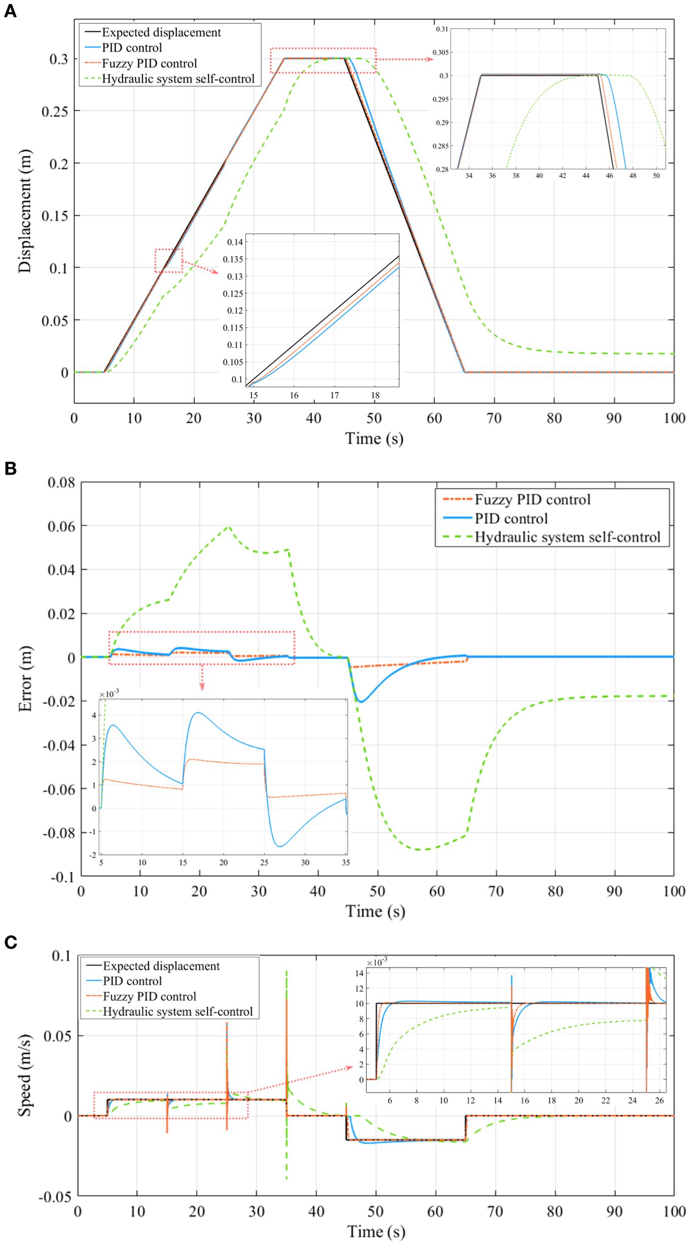
Figure 10. Electrohydraulic cosimulation results under load disturbance: (A) Displacement curve. (B) Displacement error curve. (C) Velocity curve.
The displacement curve and displacement error curve demonstrate that there is a large error between the control displacement and the expected displacement of the hydraulic system itself without the action of an external controller. Under the action of the PID controller and fuzzy PID controller, the piston rod of the hydraulic cylinder moves according to the expected displacement. These simulation results show that the displacement error fluctuates when there is load disturbance, and each controller tries to eliminate the influence of load disturbance on the movement of the piston rod. Considering the load disturbance when the simulation time is 15 s as an example, the displacement error of the piston rod under the PID controller is 4.1 mm, and the displacement error under the fuzzy PID controller is 2.05 mm. The displacement error of the fuzzy PID controller is 100% lower than that of the PID controller. The speed of the piston rod fluctuates within a small range, and the greater the change in the interference force is, the greater the fluctuation amplitude of the system, and the longer the time taken for the system to recover to the expected speed. As shown in Figure 10C, when the system is disturbed by the load, the fuzzy PID controller can control the speed of the hydraulic system quickly and accurately. In general, fuzzy PID control can significantly improve the control precision, dynamic performance, and robustness of the system.
3.2 Results of the field application
By analyzing the displacement of the hydraulic cylinder in the sea trial data, the displacement curve of the hydraulic cylinder during a single penetration process of the hydraulic system shown in Figure 11A is obtained. In this figure, the red line represents the displacement curve of the piston when the hydraulic cylinder drives the probe, and the blue line represents the displacement curve of the piston when the hydraulic cylinder pushes the sampling tube. The displacement curve of the hydraulic cylinder during the penetration process of the probe rod in Figure 11A shows that the movement speeds of the hydraulic cylinder piston and the probe rod are stable. After calculation, the average penetration speed of the probe is 0.0196 m/s, and the relative error between this speed and the ideal penetration speed is less than 3%. The penetration speed curve of the probe rod shown in Figure 11B was obtained through the displacement calculation of the hydraulic cylinder. The penetration speed is within the expected speed setting range of 5%, which meets the static penetration test standards. The penetration and withdrawal process of the sampling tube is also relatively stable, achieving the expected goals of the device design. The displacement and velocity curves show that the hydraulic system controlled by the electrohydraulic proportional valve and the fuzzy PID control strategy have favorable control accuracy and anti-interference ability. The speed control accuracy of the Seabed Cone Penetration Test and Sampling System fully meets the design and application requirements of seabed in situ exploration.
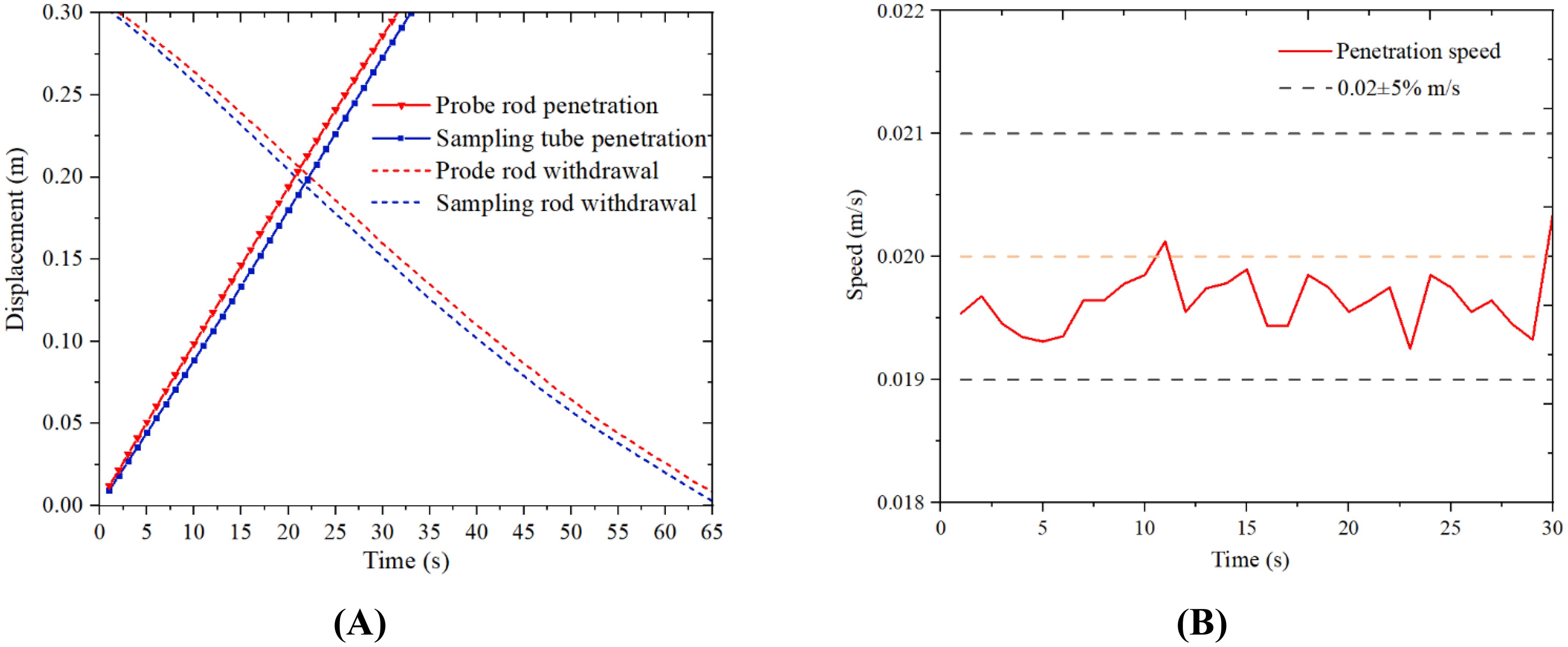
Figure 11. Displacement and velocity curves: (A) Displacement curve of the hydraulic cylinder. (B) Penetration speed curve of the probe rod.
The sea test process was very smooth, and the physical and chemical properties of 2.66 m of sediment from the 1,820-m-deep seabed were successfully obtained. Figure 12 shows the onsite test data.
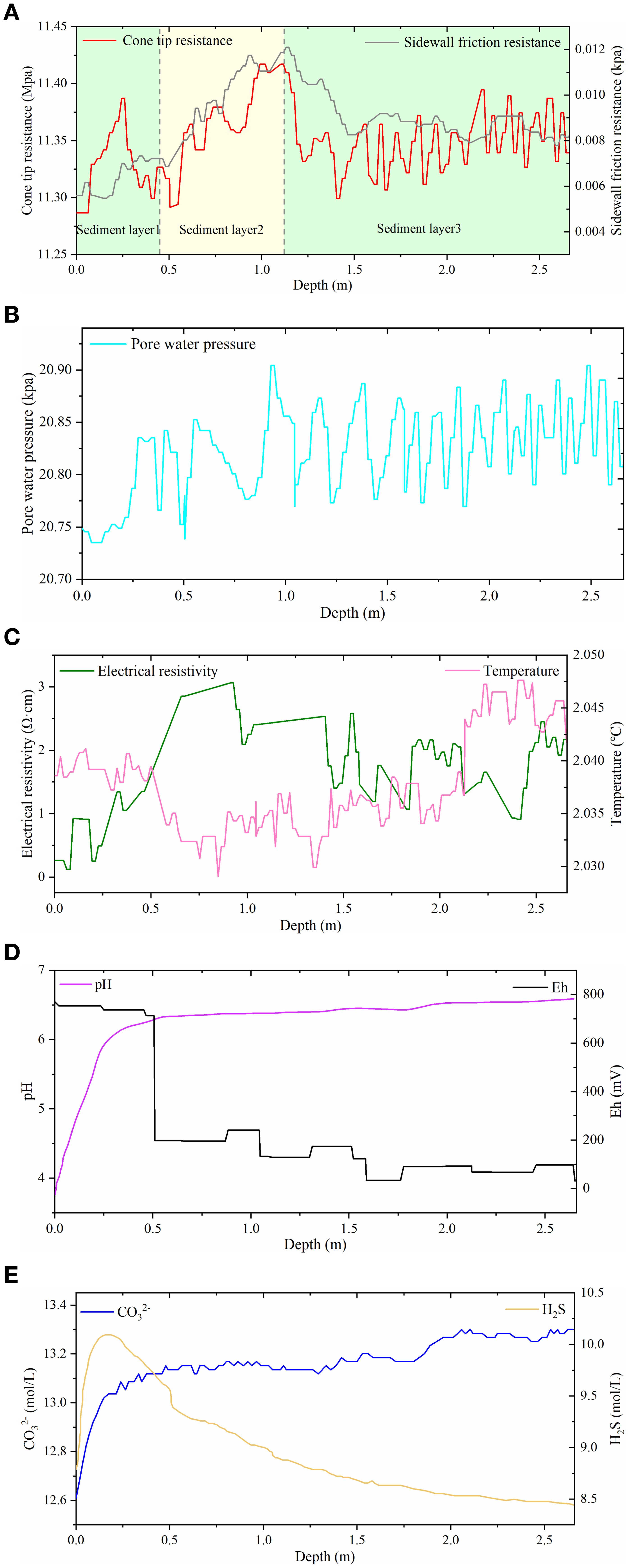
Figure 12. Variation in physical and chemical properties with depth within 2.66 m of the surface layer of marine sediments: (A) Cone tip resistance and sidewall friction resistance. (B) Pore water pressure. (C) Electrical resistivity and sediment temperature. (D) Redox potential and pH. (E) Carbonate concentration and hydrogen sulfide concentration.
The characteristics of the sediment layer in the test area can be analyzed by using cone penetration test data. The cone tip resistance and sidewall friction resistance curves in a single sediment layer unit are composed of three parts: the initial section, the constant section, and the lag section (Garziglia, 2014). In the same sediment layer profile, the initial section and the lag section constitute a transition section between two adjacent sediment layers, and a certain position in the transition section is the mechanical boundary layer between the two sediment layers. The cone tip resistance and sidewall friction resistance curves shown in Figure 12A indicate that the sediment layer within the depth range of 2.66 m can be roughly divided into three layers. Previous studies have shown that environmental temperature has a significant impact on the electrical properties of sediments (Robert and Boyce, 1968; Nobes et al., 1986). As shown in the resistivity and temperature change curves in Figure 12C, the resistivity of the sediment is approximately negatively correlated with temperature. The pore water pressure、redox potential and pH、carbonate concentration and hydrogen sulfide concentration are shown in Figures 12B, D, E.
4 Discussion
4.1 The Seabed Cone Penetration Test and Sampling System
The system developed in this study can more accurately and comprehensively obtain various physical and chemical parameters of sediments. More detailed physicochemical properties and environmental parameters of sediments are obtained by using multiparameter data. In addition, the combination of multiparameter in situ measurement and sampling technology improves the accuracy of sediment mechanics testing by mutual correction of the two test results.
4.2 Structure and penetration velocity stability of the seabed penetration platform
By conducting static simulation analysis on the key components of the seabed penetration platform, it is verified that its structural strength meets the working requirements. Meanwhile, during the on-site application of the sea trial, this platform has demonstrated advantages such as a stable structure, convenient use, and reliable functionality.
From the displacement and velocity curve of simulation and field application results, it can be seen that the hydraulic system controlled by the electro-hydraulic proportional valve and the fuzzy PID control strategy has good control accuracy and anti-interference ability. The penetration speed is within the expected speed setting range of 5%, which meets the cone penetration test standards. The speed control accuracy of the Seabed Cone Penetration Test and Sampling System fully meets the design requirements and the application requirements of seabed in situ exploration.
4.3 Study limitations
The application of CPT technology in marine engineering geological exploration in China is still in its early stages, mainly relying on foreign cone penetration test data analysis methods. In order to better obtain the mechanical properties of sediments, it is urgent to carry out a large number of field tests based on this equipment and rely on the marine geological environment of China. The analysis theory of static test results will be perfected, and a set of analytical methods and empirical formulas suitable for the characteristics of seafloor sediment in China will be formed.
The seabed penetration platform relies on its own weight to provide the reaction force during penetration. The maximum penetration capacity of the platform is therefore limited by its own weight. The future research direction is to study how to reduce the overall weight of the system while providing greater penetration force, such as the use of suction anchor technology to adsorb equipment to the seafloor.
5 Conclusions
In this study, a Seabed Cone Penetration Test and Sampling System for a 3,000-m-deep sea is designed and developed. The system can realize multiparameter in situ testing and low-disturbance sampling of seafloor sediments at a depth of 3,000 m, which can accurately and efficiently reflect the property characteristics of seafloor sediments under in situ environmental conditions. Based on the results of this study, the following are drawn.
1. To ensure the efficient and stable operation of the entire system in complex marine environments, a more compact, stable, and reliable hydraulic penetration platform has been designed. The mechanical structure, hydraulic transmission, and speed control strategy of hydraulic outburst platforms were studied and validated.
2. Existing hydraulic systems for hydraulic penetration platforms mostly use traditional switch controls, which exhibit the problem of low control accuracy. The penetration platform designed in this study implements electrohydraulic proportional control technology to realize accurate speed control of the hydraulic cylinder penetration process and ensure the accuracy of the CPT test data.
3. A revised link is added to the electrohydraulic proportional position control system, and a fuzzy PID control strategy is adopted to improve the stability, speed, and accuracy of the hydraulic control system. This control strategy can effectively reduce the influence of variable loads on the penetration velocity to ensure the stability of the penetration velocity under complex geological conditions.
Through a series of offshore applications, the success of the Seabed Cone Penetration Test and Sampling System was verified. The results demonstrate that this approach can satisfy the needs of in situ deep-sea sediment detection and can be widely used in offshore engineering applications.
Data availability statement
The original contributions presented in the study are included in the article/Supplementary Material. Further inquiries can be directed to the corresponding author.
Author contributions
CW: Writing – review & editing. LG: Conceptualization, Writing – original draft, Writing – review & editing. LJ: Conceptualization, Methodology, Writing – review & editing. WS: Supervision, Writing – review & editing. GX: Methodology, Writing – original draft, Writing – review & editing. XY: Project administration, Writing – review & editing. XL: Conceptualization, Writing – review & editing.
Funding
The author(s) declare financial support was received for the research, authorship, and/or publication of this article. This research was funded by the National Natural Science Foundation of China (No.42477153), Laoshan Laboratory (No.LSKJ202203504), the National Natural Science Foundation of China (No. 42176057), the National Natural Science Foundation of China (NSFC) (U2006213), and the National Natural Science Foundation of China (42277138).
Acknowledgments
We would like to thank LG and XL for their guidance and everyone who contributed to this article.
Conflict of interest
The authors declare that the research was conducted in the absence of any commercial or financial relationships that could be construed as a potential conflict of interest.
The reviewer XL declared a shared affiliation with the authors XY and XL to the handling editor at the time of review.
Publisher’s note
All claims expressed in this article are solely those of the authors and do not necessarily represent those of their affiliated organizations, or those of the publisher, the editors and the reviewers. Any product that may be evaluated in this article, or claim that may be made by its manufacturer, is not guaranteed or endorsed by the publisher.
Supplementary material
The Supplementary Material for this article can be found online at: https://www.frontiersin.org/articles/10.3389/fmars.2024.1377405/full#supplementary-material
References
Best A. I., Roberts J. A., Somers M. L. (1998). A new instrument for making in-situ acoustic and geotechnical measurements in seafloor sediments. Underwater. Technol. 23, 123–131. doi: 10.3723/175605498783259182
Carvajal J., Chen G. R., Gmen H. (2000). Fuzzy PID controller: Design, performance evaluation, and stability analysis. Inform. Sci. 123, 249–270. doi: 10.1016/S0020-0255(99)00127-9
Chen G. R., Pham T. T. (2001). Introduction to Fuzzy Sets, Fuzzy Logic, and Fuzzy Control Systems (Boca Raton: CRC Press), 193–197. doi: 10.1201/9781420039818
Chen Q., Xing X., Zhang Z. G., Yan J. Y. (2010). Research on hydraulic self-leveling system of seabed-base of downhole CPT. Ocean. Technol. 29, 120–123. doi: 10.3969/j.issn.1003-2029.2010.01.027
Cheng Y. R., Zeng X., Li X. Y., Zheng H. (2018). Analysis of sinking propertiess of deep-sea mining vehicles on soft sediment. Min. Metallurgical. Eng. 38. doi: 10.3969/j.issn.0253-6099.2018.06.009
Cui Y. X., Guo L., Liu T., Yang Z. N., Ling X. Z., Yang X. Q., et al. (2023). Development and application of the 3000 m-level multiparameter CPTu in-situ integrated test system. Mar. Georesour. Geotec. 41, 400–411. doi: 10.1080/1064119X.2022.2053008
Ganju E., Prezzi M., Salgado R. (2017). Algorithm for generation of stratigraphic profiles using cone penetration test data. Comput. Geotech. 90, 73–84. doi: 10.1016/j.compgeo.2017.04.010
Garziglia S. S. (2014). Seafloor instabilities and sediment deformation processes: The need for integrated, multi-disciplinary investigations. Mar. Geol. 352, 183–214. doi: 10.1016/J.MARGEO.2014.01.005
Gubon F. (1994). Development and management of marine resources in the pacific islands region: an overview of some basic issues and constraints. Ocean. Yearbook 11, 409–425. doi: 10.1163/221160094X00230
Hardison M. (2015). Correlation of engineering parameters of the presumpscot formation to the seismic cone penetration test (SCPTU). Integr. Med. Res. doi: 10.1016/j.imr.2015.09.001
Hu B. G., Ying H. (2001). Review of fuzzy PID control techniques and some important issues. Zidonghua. Xuebao/Acta. Automatica. Sin. 27, 567–584.
Ji F. D., Jia Y. G., Liu X. L., Guo L., Zhang M. S., Shan H. X. (2016). IN SITU MEASUREMENT OF THE ENGINEERING MECHANICAL PROPERTIES OF SEAFLOOR SEDIMENT. Mar. Geol. Quaternary. Geol. 36, 191–200. doi: 10.16562/j.cnki.0256-1492.2016.03.019
Krage C. P., Dejong J. T., Schnaid F. (2014). Estimation of the coefficient of consolidation from incomplete cone penetration test dissipation tests. J. Geotech. Geoenviron. 141, 06014016. doi: 10.1061/(ASCE)GT.1943-5606.0001218
Leng D. X., Shao S., Xie Y. C., Wang H. H., Liu G. J. (2021). A brief review of recent progress on deep sea mining vehicle. Ocean. Eng. 228, 108565. doi: 10.1016/j.oceaneng.2020.108565
Li G., Moridis G. J., Zhang K., Li X. S. (2010). Evaluation of gas production potential from marine gas hydrate deposits in shenhu area of South China sea. Energ. Fuel. 24, 6018–6033. doi: 10.1021/ef100930m
Li Y. H., Chen P. Y. (2023). Temperature effect on undrained mechanical properties of hydrate-bearing clayey silts in the South China sea. Energy And. Fuels. 37, 13025–13033. doi: 10.1021/acs.energyfuels.3c01971
Liu J. W., Li X. S. (2021). Recent advances on natural gas hydrate exploration and development in the South China sea. Energ. Fuel. 35, 7528–7552. doi: 10.1021/acs.energyfuels.1c00494
Liu X. L., Lu Y., Yu H. Y., Ma L. K., Li X. Y., Li W. J., et al. (2022). In-situ observation of storm-induced wave-supported fluid mud occurrence in the subaqueous yellow river delta. J. Geophys. Res.: Oceans. 127, e2021JC018190. doi: 10.1029/2021JC018190
Liu X. L., Wang Y. Y., Zhang H., Guo X. S. (2023). Susceptibility of typical marine geological disasters: an overview. Geoenvironmental. Disasters. 10, 10. doi: 10.1186/s40677-023-00237-6
Lu Y., Duan Z., Zheng J., Zhang H., Liu X., Luo S. (2020). “Offshore cone penetration test and its application in full water-depth geological surveys,” in IOP Conference Series: Earth and Environmental Science (Beijing, China), 570. doi: 10.1088/1755-1315/570/4/042008
Lunne T. (2012). The Fourth James K. Mitchell Lecture: The CPT in offshore soil investigations - a historic perspective. Geomechanics. Geoeng. 7, 75–101. doi: 10.1080/17486025.2011.640712
Luo T. T., Song Y. C., Zhu Y. M., Liu W. G., Liu Y., Li Y. H., et al. (2016). Triaxial experiments on the mechanical properties of hydrate-bearing marine sediments of South China Sea. Mar. Petroleum. Geol. 77, 507–514. doi: 10.1016/J.MARPETGEO.2016.06.019
Luo G. S., Zhang G. P. (2011). Study on walking control strategy for hydraulic system of seabed tracked mining vehicle. J. Hunan. Agric. Univ. 37, 111–114. doi: 10.3724/SP.J.1238.2011.00111
Nobes D. C., Villinger H., Davis E. E., Law L. K. (1986). Estimation of marine sediment bulk physical properties at depth from seafloor geophysical measurements. J. Geophys. Res. Atmospheres. 91, 14033–14043. doi: 10.1029/JB091iB14p14033
Pedrycz W. (1993). Fuzzy control and fuzzy systems. Res. Stud. Press., 28–36. doi: 10.1016/s0925-2312(96)90014-4
Randolph M. F. (2012). Offshore Geotechnics - The Challenges of Deepwater Soft Sediments (geotechnical special publication). doi: 10.1061/9780784412138.0010
Robert E., Boyce (1968). Electrical resistivity of modern marine sediments from the Bering Sea. J. Geophys. Res. 73, 4759–4766. doi: 10.1029/JB073i014p04759
Robertson P. K. (2016). Cone penetration test (CPT)-based soil behaviour type (SBT) classification system - an update. Can. Geotech. J. 53, 1910–1927. doi: 10.1139/cgj-2016-0044
Seifert A., Stegmann S., Mörz T., Lange M., Wever T., Kopf A. (2008). In situ pore-pressure evolution during dynamic CPT measurements in soft sediments of the western Baltic Sea. Geo-Mar. Lett. 28, 213–221. doi: 10.1007/s00367-008-0102-x
Wu S. Y., Liu J., Xu H. N., Liu C. L., Ning F. L., Chu H. X., et al. (2022). Application of frequency division inversion in the prediction of heterogeneous natural gas hydrates reservoirs in the Shenhu Area,South China Sea. China Geol. 5, 251–266. doi: 10.31035/cg2021074
Xue G., Liu Y. J., Guo L., Liu B. H. (2021). Optimization on motion-robust and energy-saving controller for hydraulic penetration system of seabed equipment. Proc. Inst. Mechanical. Eng. Part M.: J. Eng. Maritime. Environ. 235, 792–808. doi: 10.1177/1475090220970425
Yoshimura H. (2013). Interpretation of density profile of seabed sediment from nuclear density cone penetration test results. Soils. Found. 53, 671–679. doi: 10.1016/j.sandf.2013.08.005
Zadeh L. A. (1996). A rationale for fuzzy control (United States: Cambridge University Press, Cambridge, England).
Zhang W., Chen Q., Xia L. Q., Li T. (2022). Penevector marine multifunctional geological sampling/testing integrated equipment. Int. J. Wireless. Mobile. Computing. 23, 211. doi: 10.1504/ijwmc.2022.10052537
Keywords: seabed cone penetration test, multiparameter measurement, sediment sampling, seabed penetration platform, speed control, field application
Citation: Wang C, Guo L, Jia L, Sun W, Xue G, Yang X and Liu X (2024) Development and application of a 3,000-m Seabed Cone Penetration Test and Sampling System based on a hydraulic drive. Front. Mar. Sci. 11:1377405. doi: 10.3389/fmars.2024.1377405
Received: 27 January 2024; Accepted: 13 August 2024;
Published: 21 November 2024.
Edited by:
Xingsen Guo, University College London, United KingdomReviewed by:
Jiangong Wei, Guangzhou Marine Geological Survey, ChinaDapeng Zou, Guangdong University of Technology, China
Xuesen Liu, Ocean University of China, China
Piguang Wang, Beijing University of Technology, China
Copyright © 2024 Wang, Guo, Jia, Sun, Xue, Yang and Liu. This is an open-access article distributed under the terms of the Creative Commons Attribution License (CC BY). The use, distribution or reproduction in other forums is permitted, provided the original author(s) and the copyright owner(s) are credited and that the original publication in this journal is cited, in accordance with accepted academic practice. No use, distribution or reproduction is permitted which does not comply with these terms.
*Correspondence: Lei Guo, MjAxODk0OTAwMDM2QHNkdS5lZHUuY24=
 Cheng Wang
 Lei Guo
 Lei Jia
 Wenxu Sun
 Gang Xue
 Xiuqing Yang
 Xiaolei Liu
