 Artur Babiarz1
 Robert Bieda1Tomasz Borowik2Tomasz Grzejszczak1Tomasz Hartwig2
 Krzysztof Jaskot1*
 Andrzej Kozyra1
 Piotr Ściegienka2
- 1Department of Automatic Control and Robotics, Silesian University of Technology, Gliwice, Poland
- 2SR Robotics Sp. z o.o., Katowice, Poland
In this paper, the design of a five degrees of freedom (5DoF) underwater manipulator system is presented and discussed. The forward and inverse kinematics problem are solved and shown. Additionally, a system that mimics the human arm movements using a manipulator is proposed. In order to imitate the movement of the human arm, the layout diagram of the IMU sensors and the method of first calibration were presented. The work also presents a device with a simple haptic feedback used to facilitate control of the gripper. The presented approach to the design of a robot control system is dedicated to an underwater robot with the main assumption of reducing the complexity of the system. Taking into account the authors’ knowledge, this approach distinguishes the presented system from solutions known from the literature.
1 Introduction
Underwater robots have increasing applications not only in the exploration of oceans but also in freshwater bodies. The main tasks of underwater robots include reaching and exploring wrecks, providing assistance, and performing dangerous activities, such as deactivating various types of mines Yuh and West (2001); Neira et al. (2021). Underwater robots can have crews, but they can also be fully autonomous. In the case of autonomous robots, it is very important to create the appropriate accessories that enable efficient underwater manipulation by an operator on the shore or a boat. One such device is the manipulation robot Sivčev et al. (2018); Bian et al. (2022) designed an underwater vehicle manipulator system. They developed a camera system that cooperates with a 3DoF manipulator. (Maruthupandi et al., 2015) designed a visual servoing control system for a 2DoF robot. In their study, a control scheme based on a proportional-integral-derivative (PID) controller was proposed. (Kang et al., 2017a) also investigated an underwater vehicle manipulator system. In addition, to ensure the dynamic stability of the underwater vehicle manipulator system, a redundancy resolution method was proposed using a zero moment point algorithm that was tested with a redundant manipulator.
The problem of the forward and inverse kinematics for underwater manipulators was studied by (Rizzo et al., 2017; Kostenko et al., 2022; Chen et al., 2021). (Aras et al., 2017; Zhang et al., 2019) addressed the design and control of a gripper system for an underwater manipulator system.
The problem of control and dynamics of underwater manipulator systems was investigated by (Kang et al., 2017b; Han et al., 2018; Konoplin and Krasavin, 2022; Zhong et al., 2023). These studies involved, among others, the following aspects: calculation methods of inertia and the viscous hydrodynamics of underwater manipulators, analyses the dynamic model of an underwater manipulator using strip and non-strip theories based on hydrodynamics, studies on the optimization the dynamic model of an underwater manipulator considering the impact of its hydrodynamics, a control system for unmanned underwater vehicles equipped with multilink manipulators to perform contact (position-force) operations in hover mode over objects, and a double-loop fractional integral sliding mode control strategy to solve the trajectory tracking problem of an underwater manipulator with bounded external disturbances.
On the other hand, the problem of imitating human arm movements by manipulation robots is well known. Most of the solutions are described in detail in the article (Gulletta et al., 2020). We can find there the use of trajectory planning algorithms, among others, such as Rapidly Exploring Random Trees (RRT), Gradient Projection Method with RRT (GPM-RRT) or methods based on the Jacobian matrix.
The innovative contribution consists in proposing a submarine manipulator control system that imitates the movements of the human arm based on signals from IMU sensors. This approach does not require the use of advanced trajectory planning algorithms such as RRT, PRM, RRT* or similar. As a result of using the presented approach, it is possible to very easily control the movement of the robot without any other limitations than those resulting from the natural limits of human arm movement. The only requirement for the proposed solution is the calibration of the sensor system, which is described in detail in the work (Jaskot et al., 2023)1. In the literature there are a lot of papers concerning imitation of human arm movement with different kind of sensors similar to IMU. The first article worth mentioning is (Bassily et al., 2014) which presents application of the leap motion sensor. The use of leap motion sensors is based on acquiring motion parameters via a digital camera. This approach requires a human to be in a specific place at all times to ensure proper reading from the digital camera. This causes major limitations in the use of this type of sensors outdoors, where there are many factors that interfere with the proper operation of digital cameras. Moreover, the entire measurement process requires a permanent connection of the sensor via a USB port, which limits human movement and, consequently, leaves the camera’s field of view. Our experience with leap motion sensors shows that in order to control a manipulation robot, you need to learn appropriate arm movements, which are often unnatural movements. The second is work (Zhong et al., 2020) where authors describe adoption of sEMG signal to control robot motion. The main assumption of work using the sEMG signal is to use the wrist and hand as the main controller of the manipulator. The difficulty with this approach is that the authors read the movement of the appropriate wrist muscles, which correspond to the appropriate motors in the robot. The question arises about the natural movement of the arm that is to be imitated by the manipulator. In our opinion, with this approach it is not possible to accurately reproduce the movement of all arm components by the manipulator. The choice of IMU sensors is also dictated by the fact that from the measurements we obtain both the position of the elements relative to each other, as well as speed and acceleration. Moreover, the IMU sensors work wirelessly and there are no restrictions on the location of the operator.
2 General course of research
The research results presented below are a small fragment of the project concerning the construction of a submarine with a manipulation robot operating in waters with low transparency. The first assumption was that the robot could perform tasks in lakes and rivers. During the implementation of the project, the scope of operation of the underwater robot was extended to seas and oceans. The stages of work relating only to the implementation of the task of constructing a robot, its mathematical model and the human-robot cooperation system are presented below.
● Phase 1-development of assumptions for the robot’s mechanical structure - the most important are the number of degrees of freedom, power supply method, and ranges of changes in movement connections.
● Phase 2-mathematical description of the selected mechanical structure of the robot, direct and inverse kinematics.
● Phase 3-design and implementation of a prototype of a manipulation robot.
● Phase 4-development of a system imitating human arm movements and its calibration procedures.
● Phase 5-tests of the developed human-robot cooperation system in the hangar.
● Phase 6-tests of the entire system in the Baltic Sea.
It should be noted that the above description applies only to the scope of the material to which this article is devoted.
3 Modeling and construction of the manipulator
The manipulator with the kinematic scheme shown in Figure 1 was used in this project. The kinematic chain was selected to reflect the kinematics of the human arm as closely as possible. Therefore, all joints in the manipulator were rotatable. For this kinematic scheme, forward kinematics was matrices A1 − A5 describing the mutual positions and orientations of the successive links of the manipulator were determined. In these matrices, li is the constant distance between the connections measured along the i-th x-axis, λi is the constant distance between the connections measured along the i-th z-axis and θi is the angle of rotation about the i-th z-axis. Matrix E describes the position and orientation between the last link and the gripper of the robot. The matrices are defined as follows:
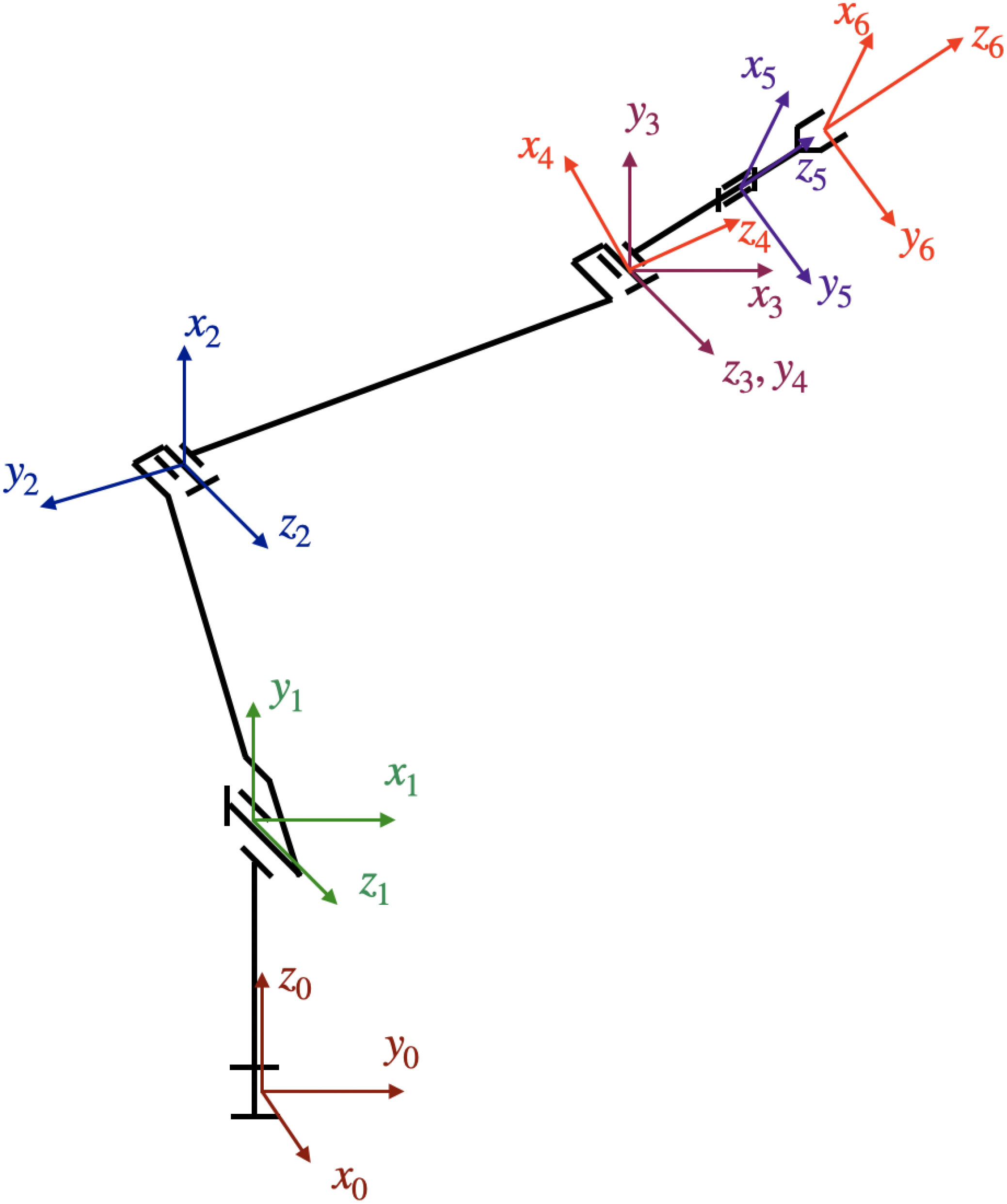
Figure 1 Kinematic scheme of the robot.
To determine the orientation and position of the last link of the robot relative to the base of the robot, the T5 matrix was determined, which is the product of the Ai matrices, where i=1,2,3,4,5. It has the following form:
where: ci, si denote cosθi, sinθi, cij, sij represent cos(θi+ θj), sin(θi+ θj), and cijk, sijk denote cos(θi+ θj+ θk), sin(θi+ θj+ θk). A three-dimensional robot model was generated based on the kinematic scheme, which is shown in Figure 2. The simulator enables the implementation of forward kinematics.
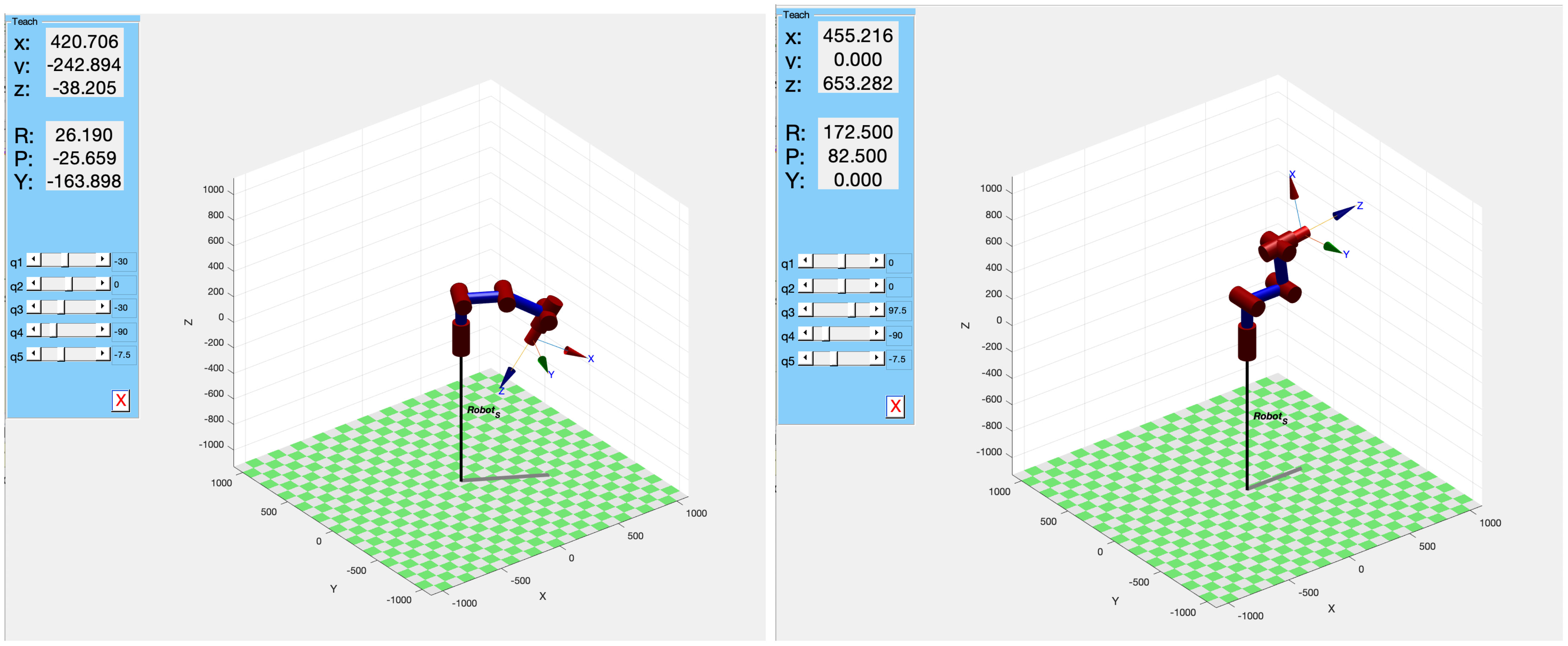
Figure 2 Simulator of forward kinematics.
To determine the inverse kinematics problem, a matrix X is required, which has the following form:
The elements of X(1: 3,1: 3) are the same as those in matrix T5 (see (1)). The final column takes the following form:
The inverse kinematics will be represented by matrix elements (Szkodny, 1995):
where T5d and Xd are given matrices. By comparing the elements of matrix T5 with the elements of matrix T5d expressed by (2) in the general form, the rotation angle of each link was determined:
Considering the above statement, we obtain:
From (3), we have formula (4):
where: .
To determine the explicit analytic form of formulas θ3 and θ2 we use the following equation:
As a result of comparing the relevant elements and simple transformations we obtain:
where:
Using the above formulas to calculate the angle θ3 and applying the expressions for the sine and cosine of the sum of the angles θ2 and θ3, we obtain:
A solution of the system of Equation 5 is defined as follows:
and finally, we obtain:
We use a similar approach to determine θ4.Then, based on the equation we have:
Hence, the expression for has the following form:
where:
The formula for θ4 is defined as follows:
The formula for finding the angle θ5 results from comparing the elements of the matrices T5 and T5d. Then, we obtain:
from which we obtain the expression for the last angle which is a parameter of the robot’s kinematics:
When applying the formulas (6), (7) and (8), the ranges of changes in the individual angles of rotation should be taken into account. A very important fact is that there may be many solutions to the inverse kinematics problem for the same vector of variables in the external space.
3.1 Construction of the manipulator
The manipulator arm consists of five links and a gripper, as shown in Figure 3.
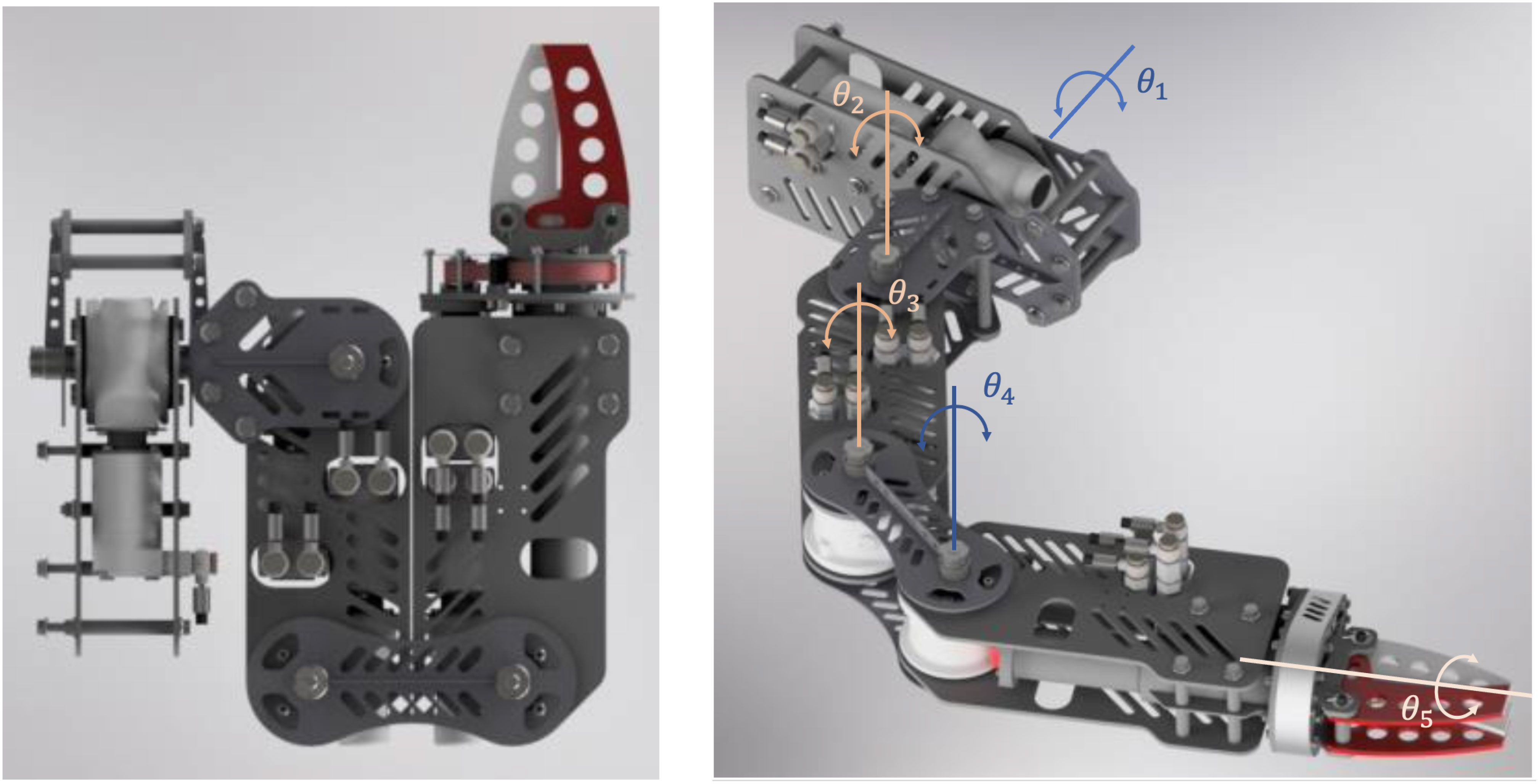
Figure 3 Manipulator in the folded position (left image) and unfolded position, with a description of the axes of rotation (right image).
The first five sections are hydraulically controlled. The last element, the gripper, is controlled by an electric motor. It is possible to measure the current of the motor, which is proportional to the force generated by the gripper. This enables implementation of haptic feedback. When the feedback is activated, the operator receives a signal informing about the force with which the gripper jaws clamp on the captured object. This is achieved by the vibration of the ERM motor (eccentric rotating mass) located on the control glove. This enables the operator to understand whether the object is being held with sufficient force without the need to look at the indicators. The dimensions of the manipulator are presented on Figure 4.
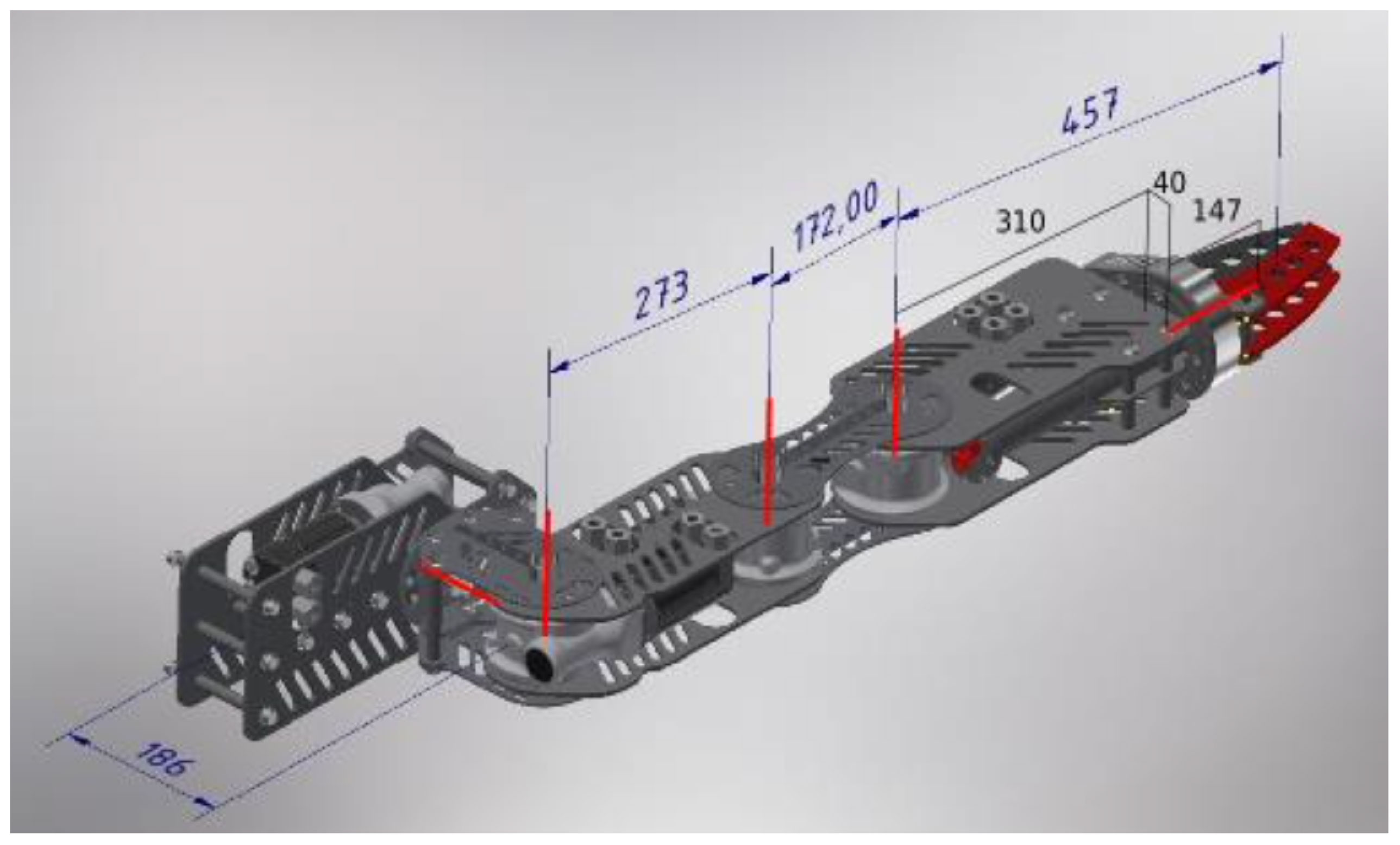
Figure 4 Manipulator dimensions.
4 Control of manipulator movements
Xsens inertial sensors were used to imitate the movements of a human arm using a manipulator. Xsens is a system composed of wireless sensors placed on an object. Each sensor includes a triaxial accelerometer, gyroscope, and magnetometer. The system allows wireless measurement of kinematic data for any motions
with high accuracy in all three planes in real-time. This system enables measurements such as position, velocity, and acceleration (Roetenberg et al., 2009).
Inertial sensors return, among other data, information about their orientation, that is a set of three angular orientation parameters (x, y, z), (roll,pitch,yaw). Xsens also offers the possibility of simple control using a linear transform.
However, a simple translation of movements is not sufficient, and this is not an intuitive control. To fully use the potential of Xsens sensors, it is necessary to recognize the position of the entire hand, that is the angles of rotation of each joint from the kinematic chain of the hand. A representative diagram of the arrangement of sensors on the human arm is shown in the Figure 5.
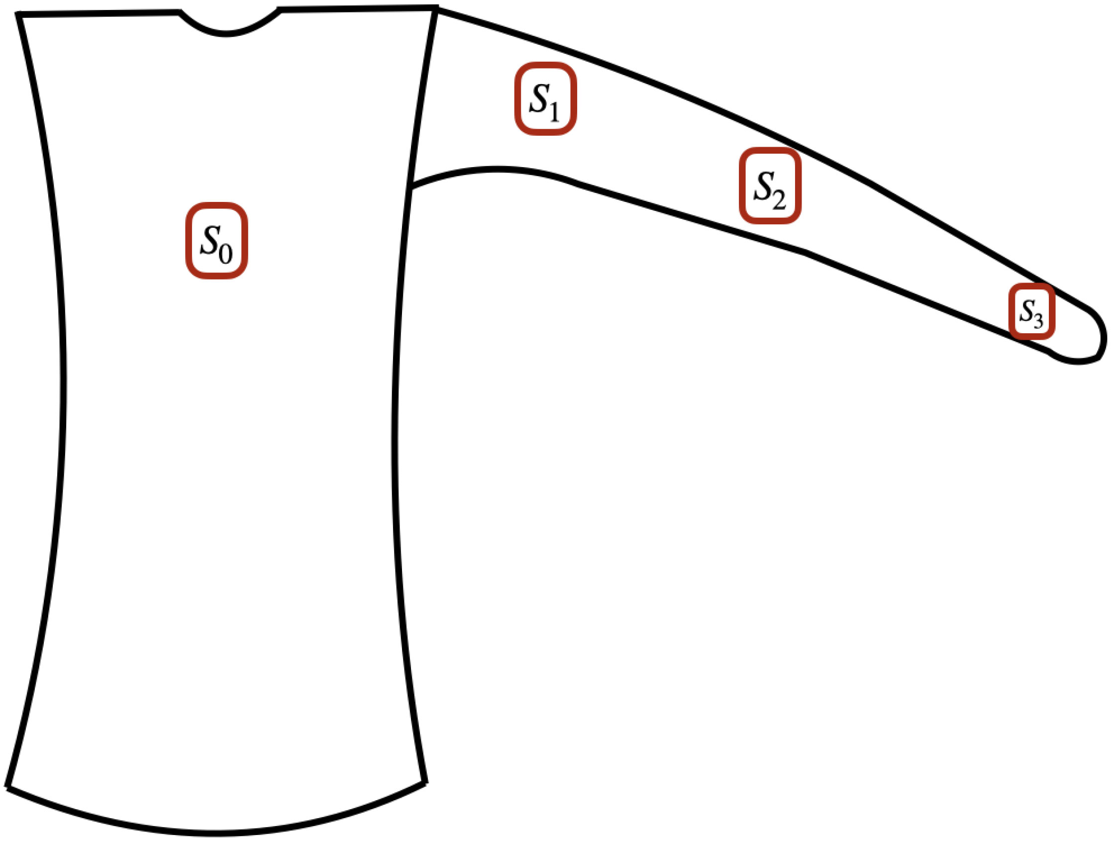
Figure 5 The arrangement of sensors.
From the point of view of application in the real world, the arrangement of sensors on the human arm is more important. For this reason, the exact arrangement of the sensors is presented in the figures below [for details, see (Jaskot et al., 2023)1]. Then, the correct application of sensors to the body is shown in Figure 6. Their orientation is not relevant because they are subject to calibration. The reference sensor should be located in a place that does not change during movement. The best position is in the cervical region or thoracic spine. Placing the sensor on the chest or shoulder will also result in correct calibration, however the accuracy will be lower. The other sensors should be located at the center of the upper arm bone, forearm, and top of the forearm.
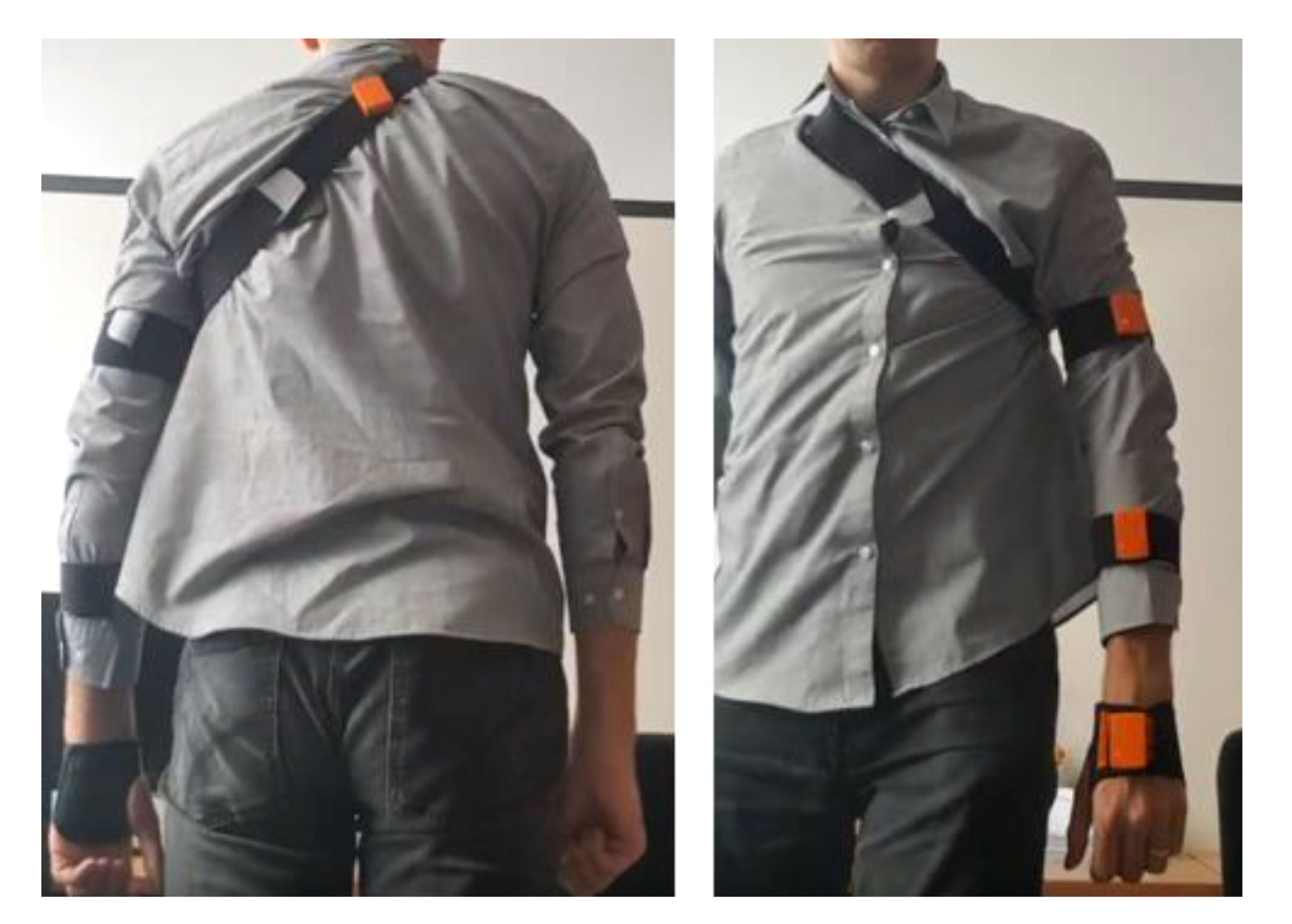
Figure 6 Example of sensor arrangement.
The calibration procedure consists of three different positions of the arm, symbolically named I, T and F, respectively Figure 7. To increase the accuracy, the points for the calibration procedure are collected for a few seconds. After collecting exactly 100 samples (in approximately 5s) for each of the three positions, the full set of 300 samples is transferred to a calibration function. After performing the procedure, the data received from the sensors can be transformed and the angles of the arm’s orientation can be viewed continuously. After completing the calibration procedure, the user can freely move the arm and a set of three angles for each of the three joints of the arm is recalculated. A characteristic feature of the proposed approach is that when bending a link, for example an elbow, the angle defining the bend of the elbow remains constant despite changes in other angles.
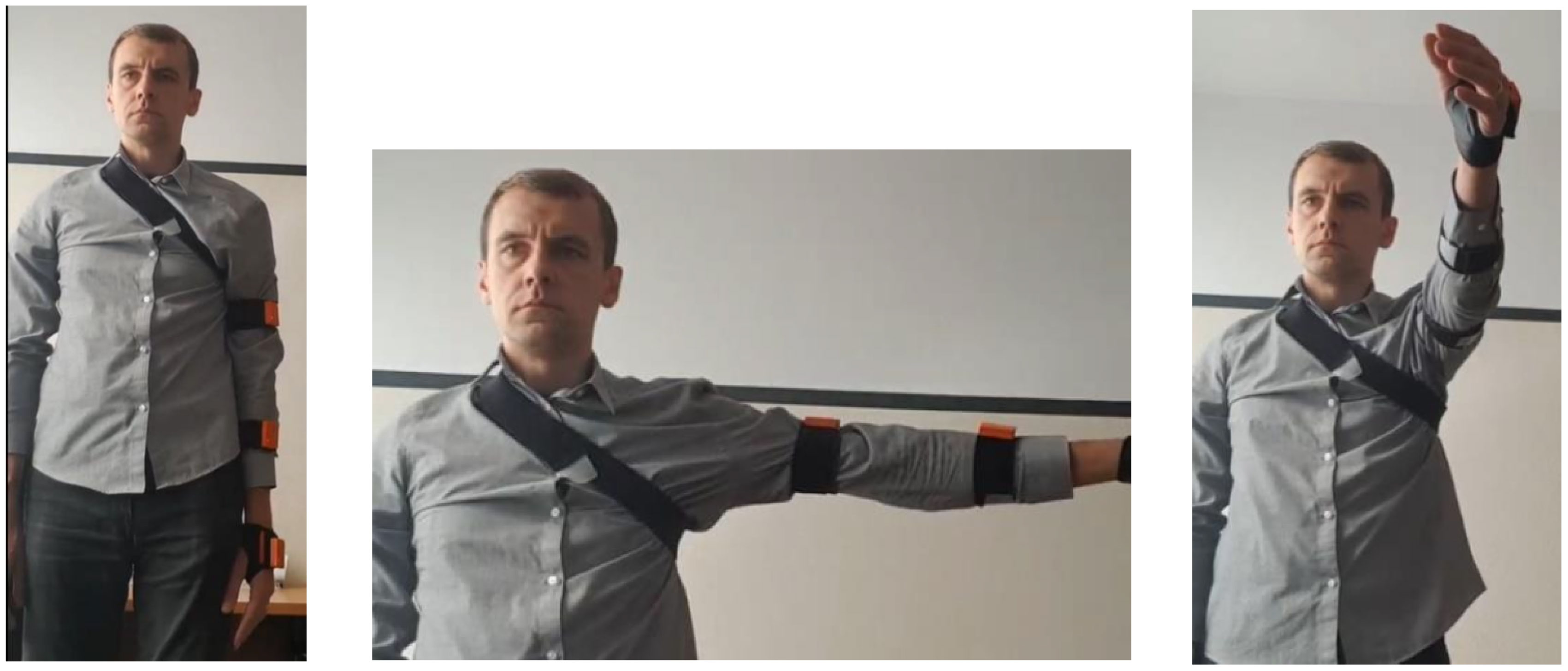
Figure 7 Arm positions required for calibration, named I, T and F.
The last element of the control system, which allows the manipulator to imitate the movements of the human arm, is the haptic glove (see Figure 8). The first prototype of the glove was based on generally available modules that contain the necessary elements. This prototype made it possible to test the planned functions. However, because of the connections between the modules, the reliability of the device was reduced. In addition, some functions could not be realized, such as measuring the wrist deflection in both directions.

Figure 8 Haptic glove.
For this purpose, a second prototype was designed and manufactured. It was adopted because of the large possibilities of distributing the elements on the ESP32 board Babiuch et al. (2019). This also allows for quick replacement of the processor in the event of failure. It compromises items such as the following ones:
● DRV2605L haptic motor driver.
● ADS1015 analog-to-digital converter for deflection and pressure sensors.
● Connectors for sensors, batteries, and OLED displays.
These components are mounted on a designed board, which significantly reduces the number of connections and allows for the construction of a smaller device. The glove is placed on the left hand. This makes it easier to test and make changes because the right hand remains free to move. Fabric strips are attached to the index finger and to the part covering the wrist. In the middle of the strip of material, there is a channel into which the FSR402 deflection sensors are inserted (exactly two sensors pointing in opposite directions, so that it is possible to measure the wrist deflection in both directions). The haptic motors are located under the wrist and under the electronics holder. Communication with the robot control system is performed via Bluetooth. The entire system is controlled by software written in C# on a PC. Measurements from the Xsens sensors and haptic glove, current angles of joints, and calibration data are read and considered. Using the Modbus protocol, the individual settings for the joints are sent to the Wago PLC controller, which controls the manipulator. It can also be controlled using a keyboard.
The designed and constructed manipulator mounted on an underwater robot is presented in Figure 9. The manipulator during operation using the proposed system is shown in Figure 10.

Figure 9 The underwater robot ready to operate.
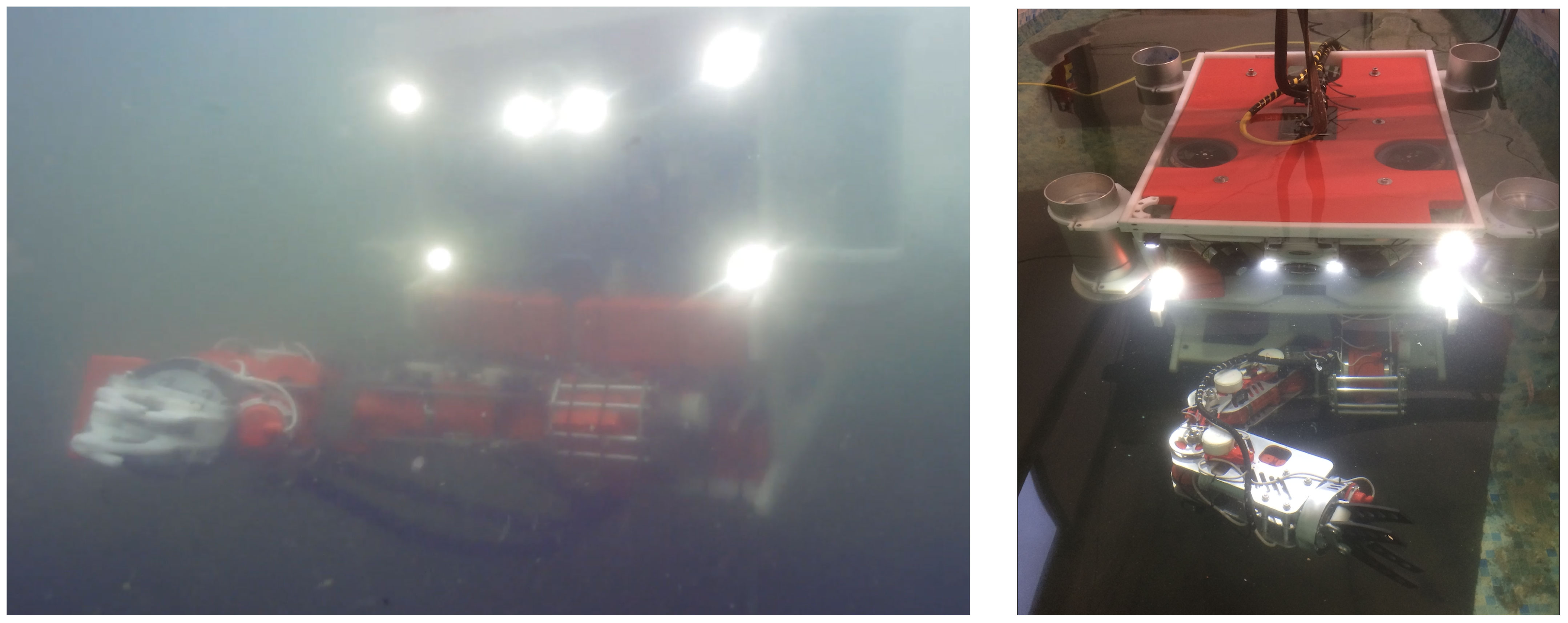
Figure 10 The underwater robot in the process of performing a certain task.
5 Example experiments
Selected results from reading individual angles from IMU sensors are presented below. The results were obtained after calibration of the sensor system, the details of which are described in (Jaskot et al., 2023)1. Figure 11 shows the orientation of the individual arm links. In Figure 12 we can see the imitation of the movement of a human arm by a real manipulation robot. The presented tests of human-robot cooperation were carried out at the headquarters of SR Robotics. Overall, the obtained test results meet the assumptions and the accuracy of movement mapping is sufficient for the correct operation of the underwater robot. The problem that occurs results from low water transparency, which makes it difficult to verify the position.
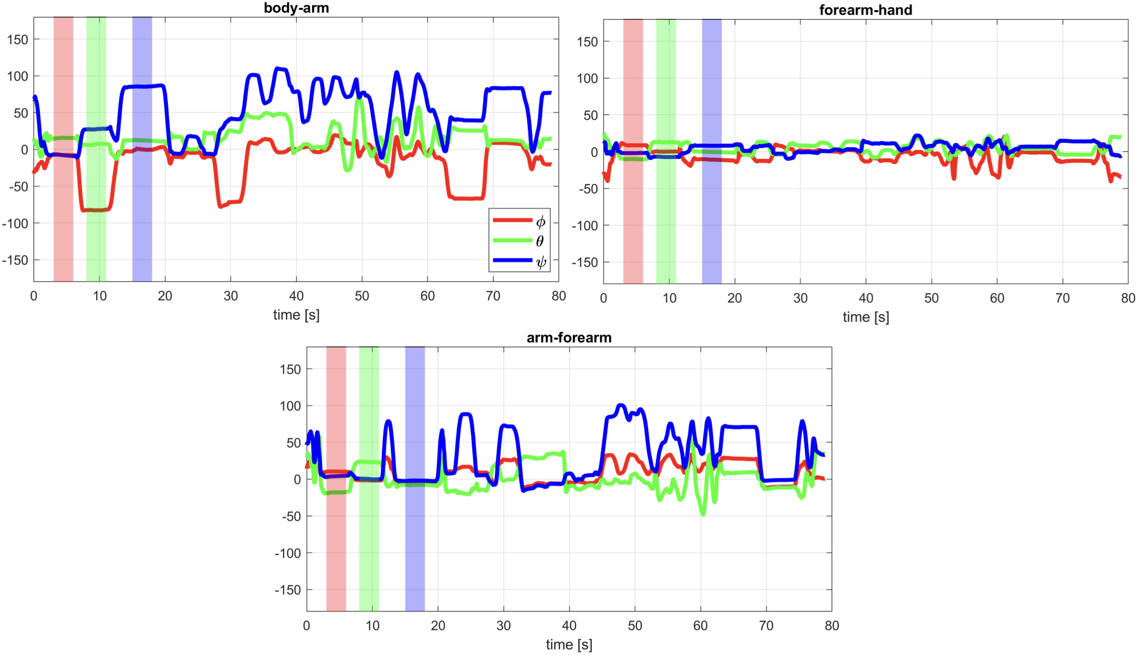
Figure 11 The date from IMU sensors.

Figure 12 A test human-robot cooperation.
and orientation of the manipulator. Additionally, the sensor system may not be calibrated due to operator immobility. Then the procedure should be repeated. The development of procedures and algorithms to improve performance in opaque water is the goal of further research.
6 Conclusions
Compared to the control of a manipulator using keyboards or joysticks, the developed control system significantly facilitates the manipulation process. The control is intuitive. The operator does not need to monitor the indicators continuously because both the gripping force and error occurrences are conveyed by the vibrations in the haptic glove. The haptic motor vibrations remain detectable even when operating in an industrial environment. However, this convenience requires additional devices that the operator must wear properly before commencing work, as well as a calibration procedure that must be executed to ensure the functioning of the system.
Data availability statement
The original contributions presented in the study are included in the article/Supplementary Material. Further inquiries can be directed to the corresponding author.
Ethics statement
Written informed consent was obtained from the individual(s) for the publication of any identifiable images or data included in this article.
Author contributions
KJ: Formal Analysis, Visualization, Writing – review & editing. AB: Formal Analysis, Visualization, Writing – original draft. RB: Formal Analysis, Software, Visualization, Writing – review & editing. TB: Funding acquisition, Project administration, Writing – review & editing. TG: Formal Analysis, Methodology, Visualization, Writing – review & editing. TH: Funding acquisition, Project administration, Writing – review & editing. AK: Resources, Software, Validation, Writing – review & editing. PŚ: Funding acquisition, Project administration, Writing – review & editing.
Funding
The author(s) declare financial support was received for the research, authorship, and/or publication of this article. The research is financed by Polish National Centre for Research and Development (NCBR) under project number POIR.01.01.01-00-0266/18: Inteligentny, efektywny system prowadzenia specjalistycznych prac podwodnych realized by SR Robotics sp. z o.o.
Conflict of interest
Authors TB, TH, and PŚ are employed by SR Robotics Sp. z o. o.
The remaining authors declare that the research was conducted in the absence of any commercial or financial relationships that could be construed as a potential conflict of interest.
Publisher’s note
All claims expressed in this article are solely those of the authors and do not necessarily represent those of their affiliated organizations, or those of the publisher, the editors and the reviewers. Any product that may be evaluated in this article, or claim that may be made by its manufacturer, is not guaranteed or endorsed by the publisher.
Footnotes
- ^ Jaskot, K., Babiarz, A., Bieda, R., Borowik, T., Grzejszczak, T., Hartwig, T., et al. (2023). Underwater human arm manipulator-system calibration. Front. Mar. Sci. Submitted.
References
Aras M. S. M., Aripin M. K., Azmi M. W. N., Khamis A., Zambri M. K. M., Halim M. F. M. A. (2017). “3dof small scale underwater manipulator — gripper for unmanned underwater vehicle,” in 2017 IEEE 7th International Conference on Underwater System Technology: Theory and Applications (USYS). (IEEE). 1–4. doi: 10.1109/USYS.2017.8309437
Babiuch M., Foltynek P., Smutny P. (2019). “Using the esp32 microcontroller for data processing,” in 2019 20th International Carpathian Control Conference (ICCC). (IEEE). 1–6. doi: 10.1109/CarpathianCC.2019.8765944
Bassily D., Georgoulas C., Guettler J., Linner T., Bock T. (2014). “Intuitive and adaptive robotic arm manipulation using the leap motion controller,” in ISR/Robotik 2014; 41st International Symposium on Robotics. (IEEE). 1–7.
Bian X., Jiang T., Guo T., Zhang Z., Wang Z., Huang H. (2022). “An autonomous underwater vehicle manipulator system for underwater target capturing,” in 2022 IEEE International Conference on Unmanned Systems (ICUS). (IEEE). 1021–1026. doi: 10.1109/ICUS55513.2022.9986631
Chen P., Long J., Yang W., Leng J. (2021). “Inverse kinematics solution of underwater manipulator based on jacobi matrix,” in OCEANS 2021, San Diego – Porto. (IEEE). 1–4. doi: 10.23919/OCEANS44145.2021.9705690
Gulletta G., Erlhagen W., Bicho E. (2020). Human-like arm motion generation: A review. Robotics 9, 102. doi: 10.3390/robotics9040102
Han L., Tang G., Xu R., Zhou Z., Liu Z., Qian J. (2018). “Double-loop fractional integral sliding mode trajectory tracking control for an underwater manipulator,” in 2018 IEEE 8th International Conference on Underwater System Technology: Theory and Applications (USYS). (IEEE). 1–6. doi: 10.1109/USYS.2018.8779116
Kang J.-I., Choi H.-S., Jun B.-H., Nguyen N.-D., Kim J.-Y. (2017a). “Control and implementation of underwater vehicle manipulator system using zero moment point,” in 2017 IEEE Underwater Technology (UT). (IEEE). 1–5. doi: 10.1109/UT.2017.7890291
Kang J.-I., Choi H.-S., Nguyen N.-D., Kim J.-Y., Kim D.-H. (2017b). “Simulation and experimental validation for dynamic stability of underwater vehicle-manipulator system,” in OCEANS 2017, Anchorage. (IEEE). 1–5.
Konoplin A., Krasavin N. (2022). Position/force control system for unmanned underwater vehicles with manipulators in the hovering mode. In. 2022 Int. Conf. Ocean Stud. (ICOS)., 31–34. doi: 10.1109/ICOS55803.2022.10033349
Kostenko V. V., Bykanova A. Y., Tolstonogov A. Y. (2022). “Developing the multilink manipulator system for an autonomous underwater vehicle,” in 2022 International Conference on Ocean Studies (ICOS). (IEEE). 45–50. doi: 10.1109/ICOS55803.2022.10033371
Maruthupandi A., Muthupalaniappan N., Pandian S. R. (2015). “Visual servoing of a 2-link underwater robot manipulator,” in 2015 IEEE Underwater Technology (UT). (IEEE). 1–2. doi: 10.1109/UT.2015.7108226
Neira J., Sequeiros C., Huamani R., Machaca E., Fonseca P., Nina W. (2021). Review on unmanned underwater robotics, structure designs, materials, sensors, actuators, and navigation control. J. Robotics 2021, 1687–9600. doi: 10.1155/2021/5542920. Graphs and Mechanics First International Conference.
Rizzo D., Bruno F., Barbieri L., Muzzupappa M. (2017). “Kinematic performances evaluation of a hydraulic underwater manipulator,” in OCEANS 2017, Aberdeen. (IEEE). 1–6. doi: 10.1109/OCEANSE.2017.8084930
Roetenberg D., Luinge H., Slycke P. (2009). Xsens mvn: Full 6dof human motion tracking using miniature inertial sensors. Xsens Motion Technol. BV Tech. Rep. 1, 1–7.
Sivčev S., Coleman J., Omerdić E., Dooly G., Toal D. (2018). Underwater manipulators: A review. Ocean Eng. 163, 431–450. doi: 10.1016/j.oceaneng.2018.06.018
Szkodny T. (1995). Forward and inverse kinematics of IRb-6 manipulator. Mech. Mach. Theory 30, 1039–1056. Graphs and Mechanics First International Conference. doi: 10.1016/0094-114X(95)00027-V
Yuh J., West M. (2001). Underwater robotics. Adv. Robot. 15, 609–639. doi: 10.1163/156855301317033595
Zhang Z., Wang C., Zhang Q., Li Y., Feng X., Wang Y. (2019). “Research on autonomous grasping control of underwater manipulator based on visual servo,” in 2019 Chinese Automation Congress (CAC). (IEEE). 2904–2910. doi: 10.1109/CAC48633.2019.8996434
Zhong H., Shen Z., Zhao Y., Tang K., Wang W., Wang Z. (2020). A hybrid underwater manipulator system with intuitive muscle-level semg mapping control. IEEE Robotics Automation Lett. 5, 3198–3205. doi: 10.1109/LRA.2020.2974700
Keywords: underwater manipulator, forward and inverse kinematics, IMU, haptic glove, calibration
Citation: Babiarz A, Bieda R, Borowik T, Grzejszczak T, Hartwig T, Jaskot K, Kozyra A and Ściegienka P (2023) Underwater manipulator that imitates the movements of the human arm. Front. Mar. Sci. 10:1271185. doi: 10.3389/fmars.2023.1271185
Received: 01 August 2023; Accepted: 14 November 2023;
Published: 01 December 2023.
Edited by:
Ye Li, Harbin Engineering University, ChinaReviewed by:
Ana Carolina de Azevedo Mazzuco, Flanders Marine Institute, BelgiumJonghoek Kim, Sejong University, Republic of Korea
Copyright © 2023 Babiarz, Bieda, Borowik, Grzejszczak, Hartwig, Jaskot, Kozyra and Ściegienka. This is an open-access article distributed under the terms of the Creative Commons Attribution License (CC BY). The use, distribution or reproduction in other forums is permitted, provided the original author(s) and the copyright owner(s) are credited and that the original publication in this journal is cited, in accordance with accepted academic practice. No use, distribution or reproduction is permitted which does not comply with these terms.
*Correspondence: Krzysztof Jaskot, a3J6eXN6dG9mLmphc2tvdEBwb2xzbC5wbA==