- 1State Key Laboratory of Marine Resources Utilization in South China Sea, School of Information and Communication Engineering, Hainan University, Haikou, China
- 2Institute of Deep-Sea Science and Engineering, Chinese Academy of Sciences, Sanya, China
- 3School of Information and Communication Engineering, Hainan University, Haikou, China
The sound velocity profile is the base of various underwater acoustic equipment. In this paper, a low-cost sound velocity profiler is designed based on the time difference method. It mainly includes three parts: the control unit, the storage module and the ultrasonic measurement module. Its overall volume is small, and the standby power consumption is low. It can be integrated into various underwater measurement platforms and profilers to realize the sound velocity measurement, and it also could be used as a self-contained sound velocity sensor. Furthermore, according to the sound velocity measurement principle and response characteristics, a calibration algorithm based on Recurrent Neural Network (RNN) and Discrete Wavelet Transformation (DWT) is proposed, which can improve the accuracy and adapt to the nonlinear response of the system by using multiple sets of time data obtained from the measurements. It is verified by calibration experiments that the neural network calibration algorithm can effectively reduce the nonlinear system error in the measurement, and its effect is better than the traditional linear regression method. The designed system prototype can achieve measurement accuracy of 0.05m/s after calibration, which can meet the needs of low-cost and high-precision underwater sound velocity measurement.
Introduction
According to the different measurement applications and methods, the mainstream methods of obtaining sound velocity profiles can be roughly divided into inversion methods (Bela Santos et al., 2017; Huang et al., 2021) and measurement methods (Didier et al., 2019). Among them, the inversion method usually uses underwater acoustic equipment to directly perform acoustic detection on a large range of seawater. One method is to use high-power underwater acoustic transceiver equipment to form an underwater acoustic network, measure the time delay of sound propagation on all paths, then estimate sound velocity profile. It is also possible to use a multi-beam echo sounder to measure the time delay of sound wave reflection in waters with known depths, and then use mathematical tools to model and invert the actual sound speed profile. The inversion method does not require any the traditional sensor in process of obtaining the sonic speed, and its measurement accuracy and efficiency are usually related to the algorithm used in the inversion. The other measurement method is to measure the sonic speed of water samples directly at a specific location. According to the measurement principle, it can be divided into indirect measurement method and direct measurement method. The indirect measurement method does not directly measure the propagation rate of sound waves in water. The sensor used is mainly the Conductivity-Temperature-Depth Profiler (CTD) (Shi, 2006). Based on the obtained temperature and salinity data, the formula is used to estimate sound velocity value of the corresponding point, where empirical formula algorithms include Del Grosso algorithm (Del Grosso and Made, 1973), Wilson algorithm (Wilson, 1959) and so on (Liu et al., 2020). In practical measurement applications, indirect measurement methods using empirical formulas usually have significant limitations (Talib et al., 2011). Since the data measured by the temperature and salinity sensor also has errors, these errors may be further amplified by the empirical formula, and the accuracy of the empirical formula itself is limited, so the calculated sound velocity value may have a large error with the real value. The direct measurement method is a more intuitive measurement method (Xue et al., 2018). Its main principle is to use an acoustic sensor to measure the wavelength or propagation time of sound waves in water to calculate the sonic speed. According to the different measurement methods, it can be divided into phase comparison method, resonance sound spectrum method and time difference method. The three methods measure the wavelength, spectrum and propagation time of sound waves respectively. The phase comparison method is to determine the wavelength by comparing the phase difference of a sound wave with a fixed frequency at two points (Chen et al., 2011; Yang et al., 2021; Cheng and Lou, 2022). Resonance spectrometry uses an excitation signal to induce the resonance of seawater in a certain space (Akbar et al., 2019; Siyu et al., 2020). The frequency of the resonance is independent of the excitation function used, but an inherent property of seawater as an elastic body. According to the change of the resonant sound spectrum of the object, the parameters such as the density, elastic coefficient, acoustic impedance and sonic speed of the object can be studied. The time difference method is to directly measure the time required for the sound wave to propagate a fixed length in the seawater to be measured. Compared with other sonic speed measurement methods, the time difference method has a faster response speed. The sensor using the time difference method is small in size and low in power consumption, hence the time difference method is very suitable for field measurements (Ko et al., 2012; Sun et al., 2020; Liu et al., 2021; Sun et al., 2021; Zhang et al., 2021). Most underwater sound velocity measurement sensors and profilers on the market use the time difference method. The most critical step in the time difference method is to measure time. The smaller the volume of the sound velocity probe, the higher the accuracy of time measurement is required. With the rapid development of various radar, ultrasonic or laser-based ranging sensor technologies in recent years, the design process of Time to Digital Converter (TDC), the core component used to measure time, has also become more and more mature. There are a large number of TDC chips that can meet the requirements of low-cost and high-precision time measurement, and their time resolution is usually in the picosecond level, which can also meet the needs of small transit-time sound velocity measurement sensors (Rostami et al., 2020; Garzetti et al., 2021).
In this paper, a low-cost, low-power, miniaturized time-difference sound velocity profiler is designed, and a dedicated calibration algorithm for the system is proposed based on RNN and DWT. In order to reduce the system’s demand for hardware computing power as much as possible, the measurement system adopts a marginal design. The main control module in the sound velocity profiler is only responsible for process control and data interaction, and all computing processes are completed by the data processing terminal. The calibration algorithm of the measurement data is based on the RNN framework, which can calibrate the nonlinear error in the sensor response curve to adapt to the low-cost probe with poor acoustic performance, and can fuse multiple measurement data at the same time to utilize the repeated information in the measurement data to improve the measurement precision.
The principle of time difference sound velocity measurement sensor
According to the types of measurement circuits, the time-difference sound velocity sensor can be divided into ring-sound type (Yang et al., 2021) and transit time type (Kalisz, 2003). The ring-sound method, also known as the cyclic pulse method, is a very classic time difference measurement circuit. The basic idea is to connect the water to be tested and the transceiver transducer in series as a delay device in a self-excited circuit, and then measure the period or frequency of the pulse excitation signal in the circuit to obtain the specific time delay of sound propagation. The ring-sound sensor will continuously repeat the measurement process during the working process, and through a reasonable calculation method, the effect similar to the averaging of repeated measurements can be achieved to improve the accuracy of the measurement results. The disadvantage is that the ring-sound sensor needs to repeat the measurement continuously, which will inevitably greatly improve the overall power consumption and response time of the system, and because the signal generation and detection depend on the analog circuit, it is difficult to accurately analyze the noise and other disturbances in the circuit. Time of Flight (TOF) sensor can measure the propagation time of a single sonic speed. Due to the high demand for hardware in principle, its appearance and development are later than the ring-sound type. The transit time measurement method using the reflective structure is also called the pulse echo method. The circuit will directly measure the time required for the sound wave to be sent to the echo signal to be received, thereby obtaining the sonic speed in the water. The accuracy of TOF measurement is related to the time resolution and propagation distance of the measurement system. When the sonic speed in the water to be measured does not change much, the longer the distance of the sound propagation path and the more accurate the time resolution, the more accurate the measured sonic speed.
The design of system
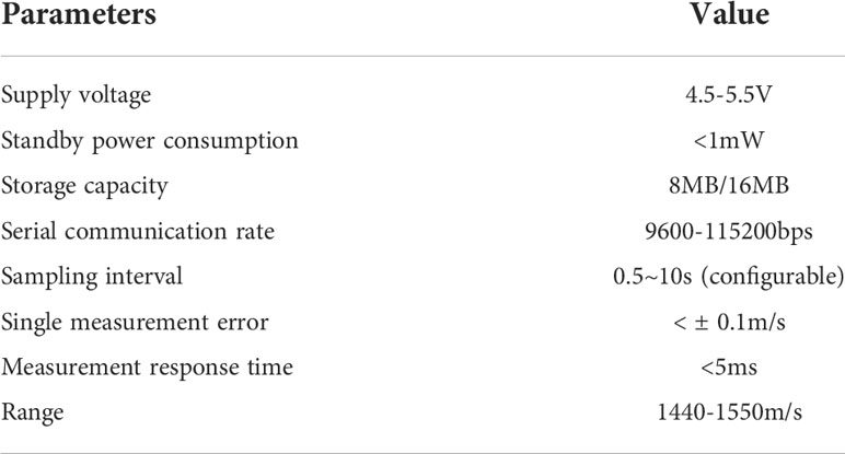
The sound velocity profiler designed in this paper is intended to be used as a general-purpose sound velocity sensor module to be applied to various small underwater observation platforms. In order to adapt to different platforms and facilitate secondary development, the designed software and hardware system can be used as a lower module. The serial port receives commands and sends data, and it can also be used independently as a self-capacitive sensor when only the power supply battery is connected. Some parameters of the system are shown in Table 1.
Hardware design
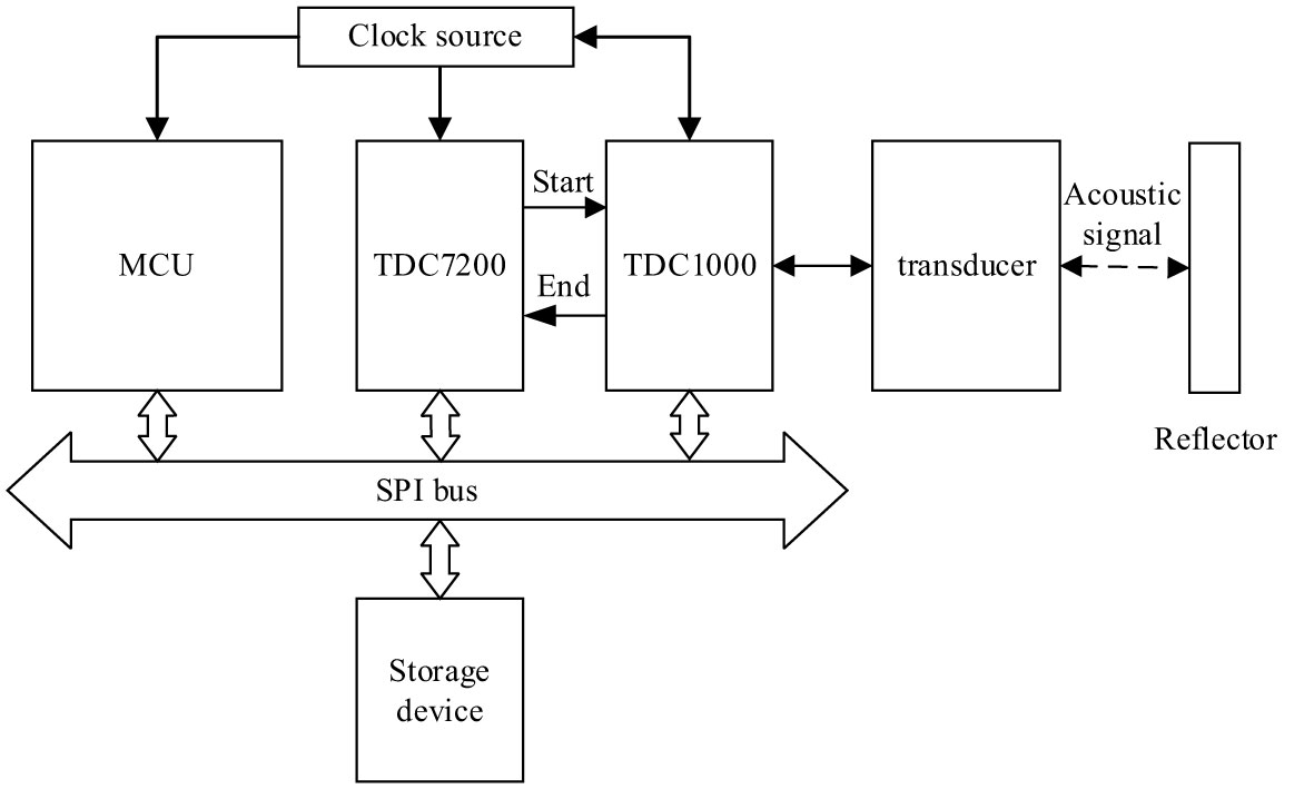
The designed sound velocity profiler is integrated on a small PCB board, and the overall hardware architecture is shown in Figure 1. The circuit can be divided into four parts: power supply module, ultrasonic measurement module, data storage module and main control.
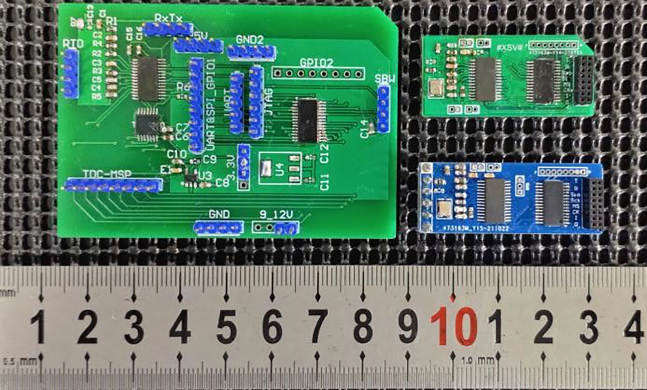
In the process of hardware development and debugging, three versions of PCB boards have been designed successively, and the corresponding PCB is shown in Figure 2. The first version of the PCB (left) uses two layers of wiring, with a length of 74mm and a width of 52mm. The main signal lines on the board have terminals for easy debugging, which are mainly used to verify the working principle of the hardware; the second version of the circuit (upper right) with a high-precision oscillator is used as a synchronous clock signal, and the regulated power supply circuit and common terminal layout are optimized; the PCB adopts four-layer wiring, and the length and width are reduced to 38mm and 18mm, which are mainly used for system performance testing. The third version of the circuit (bottom right) adds a memory module on the base of the second version, including a flash chip and an SPI interface for an external SD card; the PCB is 40mm long and 15mm wide, the layout of components has been further optimized, and the spacing and arrangement of some signal lines are adjusted to reduce crosstalk.
In order to meet the long-term work needs of the system on various underwater observation platforms and the low-cost design characteristics, MSP430G2XX Series MCU produced by Texas Instruments is selected as the main control chip, with an area only half of that of other conventional MCU of MSP430 series, which is suitable for the hardware system design with limited space. In this design, about 32 bytes of data from the TDC chip need to be recorded for each measurement, and the storage in the MCU is very limited, so an external storage device is required to store the measurement results to meet the non-real-time measurement requirements of self-capacitance sensor data. The circuit supports two kinds of storage devices, micro SD multimedia memory card (MMC, Multimedia Memory Card) and W25QXX series chips. Among them, the W25QXX memory chip is integrated on the PCB, and the micro SD card is externally connected. In the sensor platform containing the SD card storage device, the reserved SPI bus interface can be directly connected to the SD card to realize centralized data storage. The ultrasonic measurement module is the core device of the whole system, which includes two time-to-digital conversion chips TDC7200 and TDC1000. The TDC7200 undertakes the task of high-precision timing in the circuit, and can precisely measure the time interval between the start signal and up to five end signals. The chip contains a high-frequency oscillator and is equipped with a calibration function, which can compensate for the timing deviation caused by factors such as temperature changes according to the external clock time base, so as to obtain picosecond-level accuracy. The TDC7200 also supports multi-cycle measurements, where results from up to 128 measurement cycles can be added for averaging for higher measurement accuracy. Therefore, it is suitable for the design of sensor calibration algorithm based on neural network for this system. TDC1000 is an analog front-end for ultrasonic induction, which is directly connected to the transducer probe. The pulse frequency of the transmitted signal, the amplification gains of the received signal and the detection threshold can be adjusted according to the configuration. The internal amplifier has low noise and interference, so as to meet the requirements of high precision ultrasonic testing.
The design of software control process
In this sound velocity profiler, the MCU is only responsible for the enabling and data transmission of each chip on the control board, and it does not receive the analog signal generated during the measurement process. The processing of the ultrasonic signal and the precise timing are realized by two time-to-digital conversion chips respectively. The program running on the measurement system mainly includes the main loop, measurement program, data recording and serial port services.
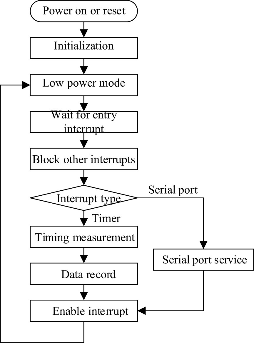
The main loop is shown in Figure 3. The main program is responsible for receiving the timing interrupt from the timer and the receiving interrupt of the UCA0 serial port under the UART configuration. The interrupt service corresponds to the timing measurement program and the serial port control program respectively. In the running cycle, the MCU can be divided into two states: work and sleep. When waiting for the measurement, the MCU enters the low-power mode to reduce power consumption. At this time, the global interrupt is enabled, and the MCU will be woken up by waiting for the timer or serial port interrupt. When the system receives the interrupt message, it determines the program to be run according to the current interrupt type, and it enters the sleep mode again after executing the target program to save power consumption. During the execution of one interrupt, the MCU will shield other interrupts to avoid data conflicts. In a measurement cycle, the time required to measure data and communicate is very short, and the MCU does not need to perform operations most of the time, and is in a dormant state, which can greatly reduce the average power consumption of the main control module.
The measurement program is mainly responsible for controlling the TDC chip to perform a measurement and reading the measurement results into the memory. It also updates the system time and TDC measurement configuration before the measurement starts. After the serial port transmission is enabled, the data will be sent directly through the UART serial port.
The data logging system supports two storage devices, SD card and flash memory chip, which can be selectively used according to actual needs. If one of the storage devices is not connected or the writing fails, it will skip and continue. Some SD cards do not support the reading and writing of data of any size, so it is necessary to set a buffer in the program, and it writes all the data in the buffer to the SD card after the amount of data reaches a certain level. When the serial port receives data, the serial port receiving interrupt will be generated. At this time, the serial port service program is opened, and the received data is read one byte at a time. When the end character is received, or the serial port has not received data for a certain period of time, the corresponding received instruction will run.
Echo signal modelling
In the narrowband ultrasonic ranging system, the time domain waveform of the ultrasonic echo signal can be expressed as a mixed exponential model as shown in Equation 1.
where A is the amplitude of the signal; m is an integer, usually 1, 2 or 3 depending on the system parameters; f is the center frequency of the signal, which is 1MHz in this system; φ is the initial phase, generally 0. In the parameters of the simulated echo signal, the larger the value of m, the slower the envelope attenuation of the echo signal. According to the actual situation, m=2 is selected as the simulation parameter, and the simulation image is shown in Supplementary Figure 1.
The echo waveform actually measured when the water temperature is 25°C is shown in Supplementary Figure 2. It can be seen that the measured waveform is quite different from the single-channel echo signal under the mixed exponential model in Supplementary Figure 1. Considering the overall small size of the sensor, the transducer and the reflective surface cannot be equivalent to an ideal sound source during the sound propagation process, and multipath effects may occur during the propagation process. After adjustment by the simulation experiment, the response of the multipath channel is shown in Supplementary Figure 3, i.e., the channel model after combining the multipath effect and the mixed exponential model is similar to the actual response of the transducer. The simulated waveform after adding the multipath effect is shown in Supplementary Figure 4.
Response performance test of sound velocimeter
Because the calculated TOF contains the systematic error caused by the characteristics of circuit components and sensor structure, it cannot be directly used as the ultrasonic propagation time, which will result in the low sound velocity value, thus the data need to be calibrated. Under the condition of fixed distance, the sound velocity is inversely proportional to time, so after selecting the reciprocal of any timing result as the reading of the sensor, the calibration curve of the sensor can be linearly fitted by the least square method. Under the ideal condition without any interference factors, the echo signal waveform received by the transducer during each measurement is identical, and the distance between each detected zero crossing point is equal to the period of the ultrasonic signal, so the distance between each zero-crossing point is fixed. When there is only additive white Gaussian noise, the five zero crossing moments can be approximately regarded as five measurements of the same TOF value. Theoretically, using the average value of the five time points as the measurement result of the sensor can improve the measurement accuracy. However, due to the multi-path fading effect and frequency selective characteristics in the sound propagation process, the phase difference of each signal may not be fixed, resulting in the position of the five zero crossings detected in the echo being affected to some extent.
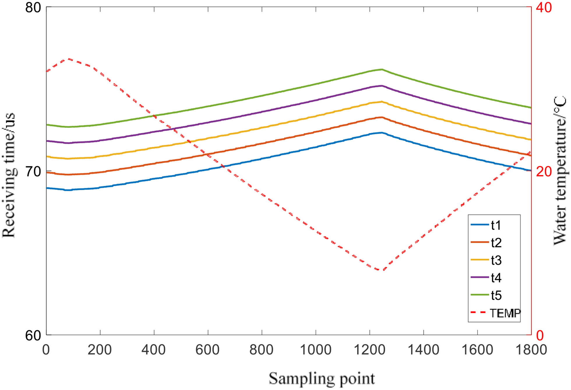
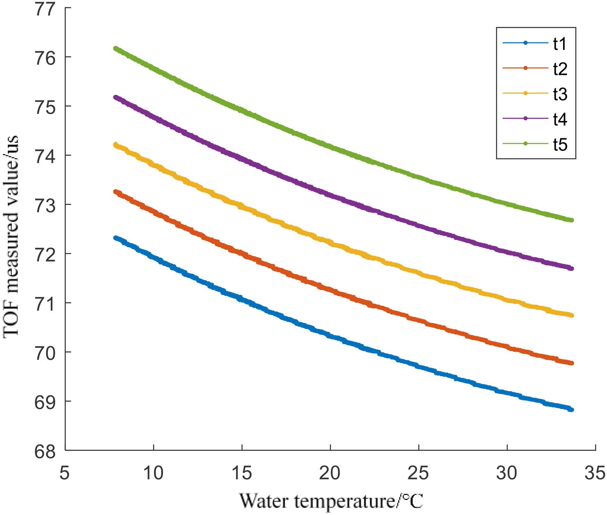
In order to verify whether the actual performance after averaging the five time points measured by the sensor meets the needs of sound velocity measurement, a principle verification experiment was carried out in a laboratory water tank. Place the sensor to be tested in the water tank, control the water temperature to change continuously within about 8°C ~32°C, and the sensor samples every 1 second. MATLAB is used to read and process the collected data through the serial port. Figure 4 shows that five zero crossing times collected by the sensor and the change of water temperature with time. In order to more clearly display the response of the sensor, take the temperature in the water tank as the abscissa and the measured five time points as the ordinate, and only select the image drawn by the experimental data whose temperature is within the range of 15 to 20°C during the process of temperature rise and fall, as shown in Figure 5.
The trends of the measured values in Figures 4, 5 shows that there is a small nonlinear error related to temperature changes in the fitting results, and the five measurement points are affected to different degrees, and the nonlinear characteristic of t3 is the most obvious. The sound velocity measurement equipment requires very high accuracy for time measurement, and the results of the response test show that there is a certain nonlinear error in the measurement results of the sensor, and the averaging method cannot completely solve the nonlinear error. The accuracy is difficult to meet the needs of practical applications under specific conditions. Designing and developing a data calibration algorithm for the data receiving end is an optimal solution to further improve the measurement accuracy.
Design of sensor calibration algorithm based on RNN and discrete wavelet decomposition
Neural network (Abiodun et al., 2018) is an artificial intelligence algorithm whose structure is similar to the way of neural connections in living organisms. The network consists of an input layer, an output layer and a hidden layer. Each layer has several neurons, and its input can be a scalar, a vector or a higher-order tensor. This structure is also called a multi-layer perceptron (Multi-Layer Perceptron, MLP). Neural networks with multiple hidden layers are called deep neural networks. Through the training process, deep neural networks can simulate the input-output relationship of any function, or learn the abstract rules between input and output, and are widely used in data fusion and compression, curve fitting (Shao et al., 2016) and pattern recognition (Mikheev et al., 2020; Li et al., 2021). Generally speaking, the more layers a neural network has, the stronger its ability to learn details and abstract information, and the longer the training process will take. The number of layers of the hidden layer can be adjusted according to the needs. The selection of the number of neurons in each layer in the layer has no theoretical guidance and needs to be determined by experimental comparison. The neurons of two adjacent layers are connected to each other, and the input vector Xk of the k-th layer can be regarded as the sum of the vector bk after multiplying the output vector Yk-1 of the k-1th layer by the matrix Wk. This matrix is called the weight matrix and the vector is called the bias vector. Then this process can be expressed in the form shown in Equation 2.
In order to correct the nonlinear error in the sensor response curve and further improve the measurement accuracy and usability of the designed low-cost sound velocity profiler, a sensor calibration algorithm based on RNN (Lv et al., 2021) and Discrete Wavelet Transform (DWT) (Chaubey and Atre, 2017) is designed in this paper, which can calculate the sound velocity value by combining the available information from the five zero-crossing measurements. RNN is used to process time-serial signal which is similar with sequential received measurement signal. Specifically, RNN can predict future signal with past information, it has good performance in the prediction and analysis of nonlinear time series signal. The RNN can be represented by
where yj is the output of j-th neuron, f(·) is the activate function, ωji denotes connection weight between j-th neuron and i-th neuron, zi(t) represents recurrent input yi or external input xi.
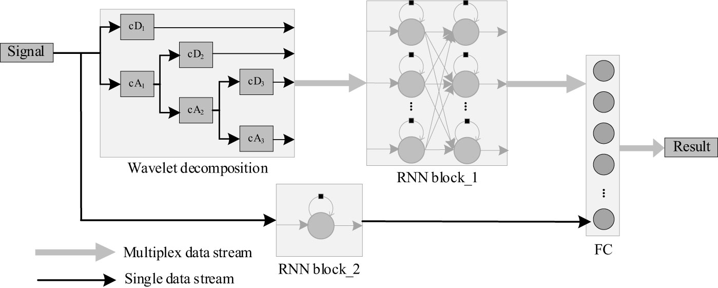
Discrete Wavelet Transform (DWT) can decompose signal into a series of lower resolution components with filtering and decimating operations. Specifically, high-pass and low-pass filters are used to get corresponding components and coefficients which are consisted with approximation (cA) and detail (cD) coefficients, as in shown in Figure 6. In order to get robust relationship between predicted results and inputs, the input signal is decomposed with DWT into four component coefficients (cD1, cD2, cD3, cA3), and then the four coefficients are sent to RNN block_1 to get more refined temporal correlation and output high-dimension result. Meanwhile, the original signal is processed with RNN block_2 to get rough predicted result. At last, the outputs of RNN block_1 and RNN block_2 are concatenated with a Full Connection (FC) layer, and the result will be gotten.
RNN is suitable for processing sequence data using historical information, and since the measurement data are sequential and are interrelated, RNN can be used to improve the fitting accuracy and give stable results compared with direct calculation results. At the same time, DWT decomposes the data into a series of components with different frequencies so that the RNN can use rich fitting features. Therefore, stable sonic speed prediction can be achieved by combining the characteristics of RNN and DWT.
The commercial SVP as a reference and the probe of the sound velocity measurement device designed in this paper were placed adjacent to the water tank, and the measurement experiment was repeated to collect enough data as a dataset for training the neural network. The sampling interval of each sensor is set to 0.25 seconds, and the water temperature in the water tank is controlled to change from 35°C to 7°C within three hours and then return to 30°C. After that, 54,000 groups of continuous sensor measurement data were collected. In contrast, the SVP sensor used will return a blank value when the sound velocity data cannot be collected. The point where the blank value is located needs to be replaced by the average of the two nearest valid points to complete the measurement data.
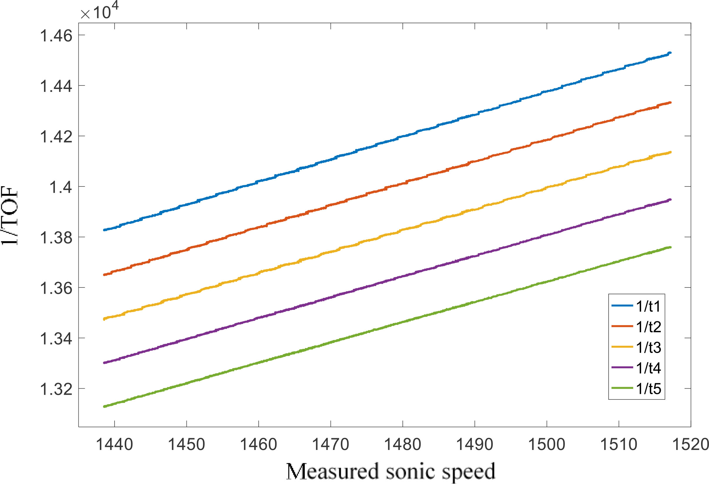
Take the reciprocal of the five TOF time values as the ordinate, and the sound velocity value measured by the SVP as the abscissa, draw a relationship curve. The least squares method was used to linearly fit the measured data, and outliers with residual values greater than three times the standard deviation were eliminated from the data. The final data are shown in Figure 7.
Due to the uneven temperature change, the measurement densities of the two sound velocity sensors in different temperature ranges are different during the experiment i.e., the measurement points in the range close to the highest temperature and the lowest temperature are denser, while the measurement points in the middle area are sparse. In addition, there is a certain amount of noise in the measurement results, so using noisy data as a training set will affect the performance of neural network training. In order to make the points in the data set continuous and evenly distributed, and to suppress random errors in the measurement data to a certain extent. First, use the joint interpolation method to increase the resolution of the measured data to 0.001m/s, so that the measured data is evenly distributed along the abscissa, and then perform an average downsampling with a step size of 8 on the interpolated data, and finally use the interpolation method to bring the resolution back to 0.001m/s. Taking the processed ordinate vector and abscissa as the input value and the target value, respectively, the training data set is obtained.
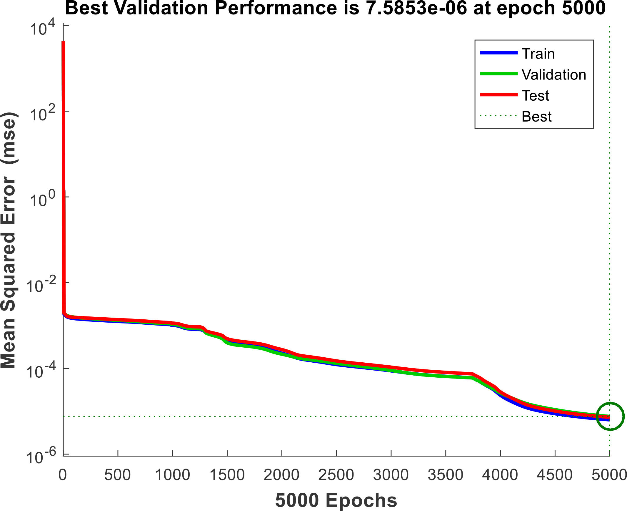
The neural network used for data calibration and fitting is built by MATLAB, and the activation function is the hyperbolic tangent function. The performance of data fitting is poor when the network structure is simple, and the excessive number of layers and neurons in the network will increase the computational complexity and lead to over-fitting. In order to determine the number of layers and neurons of the neural network, a continuous section is intercepted from the data set obtained in the previous section to test the relationship between the performance of the neural network and the parameters of the network construction, and finally the number of hidden layers in the built network is determined to be 2, each layer contains 20 neurons. 15% of the collected datasets were selected as test set and validation set, and the rest were used as training data. Set the number of training times to 5000 times. During the training process, the loss function of the neural network on the test set, training set and validation set varies with the number of training times as shown in Figure 8. The final mean square error of the network on the training data set is 7.5853×10⁻⁶, the fitting accuracy is calculated by three times the standard deviation, the result is about ±0.00826m/s, which can meet the needs of sound velocity measurement calibration. However, the noise in the measurement data is removed in the data processing process, and there may be overfitting. The actual measurement accuracy of the neural network needs further experimental verification.
System software and hardware testing
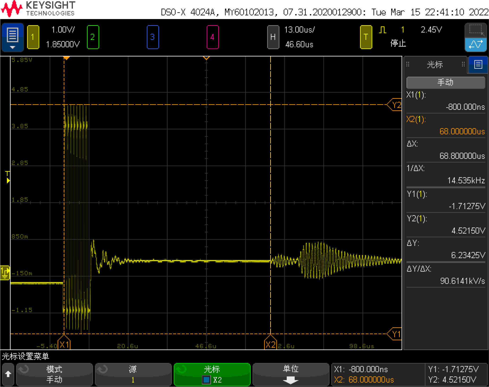
First, connect the system to the 5V power supply and disconnect all other connections. The measured current of the system in the standby state is about 190μA. Then connect the UART serial port of the system to the PC to verify its basic functions. Use an oscilloscope to connect both ends of the transducer, and place the probe in water at room temperature. The waveform on the oscilloscope during measurement is shown in Figure 9. The two waveforms are the transmit signal and the echo signal. Use the oscilloscope to measure the time between the two signals. The interval, about 68 us, corresponds to the actual measurement of the sensor.
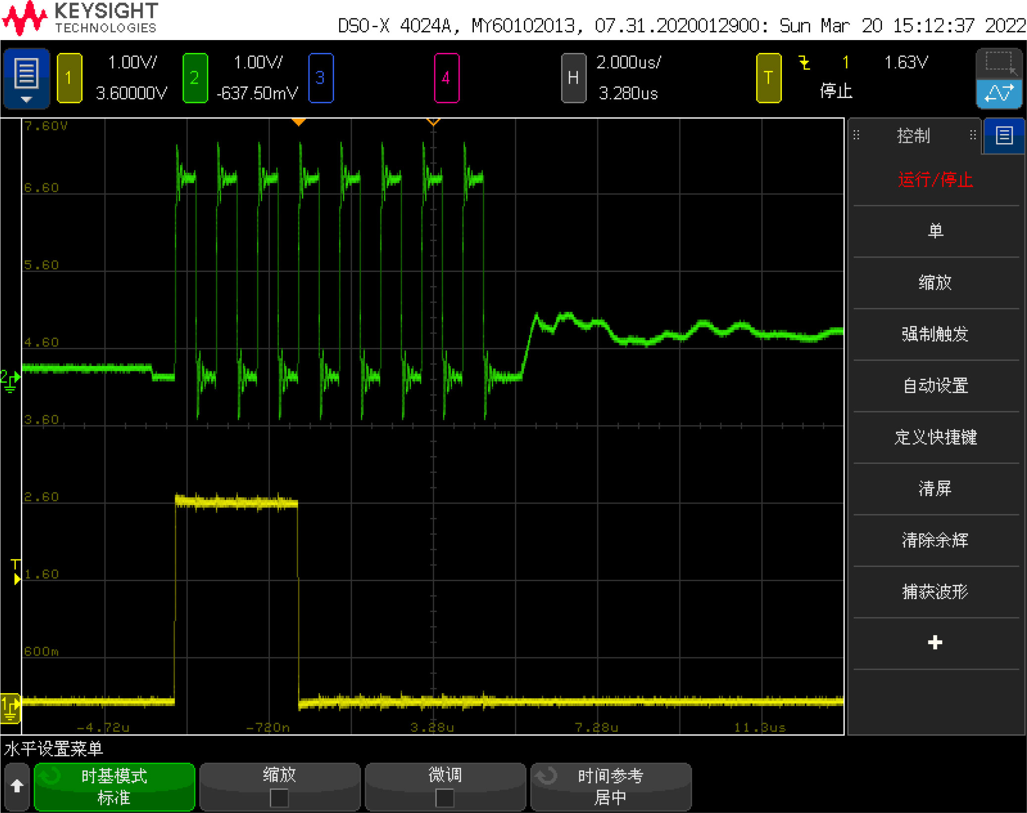
Use an oscilloscope to connect the start signal line and the transducer signal line of the TDC1000. The signal waveform measured at the beginning of the measurement is shown in Figure 10. The upper and lower signal waveforms are the 1MHz ultrasonic pulse signal and the start signal respectively. It can be seen that the two signals are sent out synchronously, but there is still a level change on the transducer after the ultrasonic pulse signal is emitted, which may be related to the frequency response characteristics of the transducer.
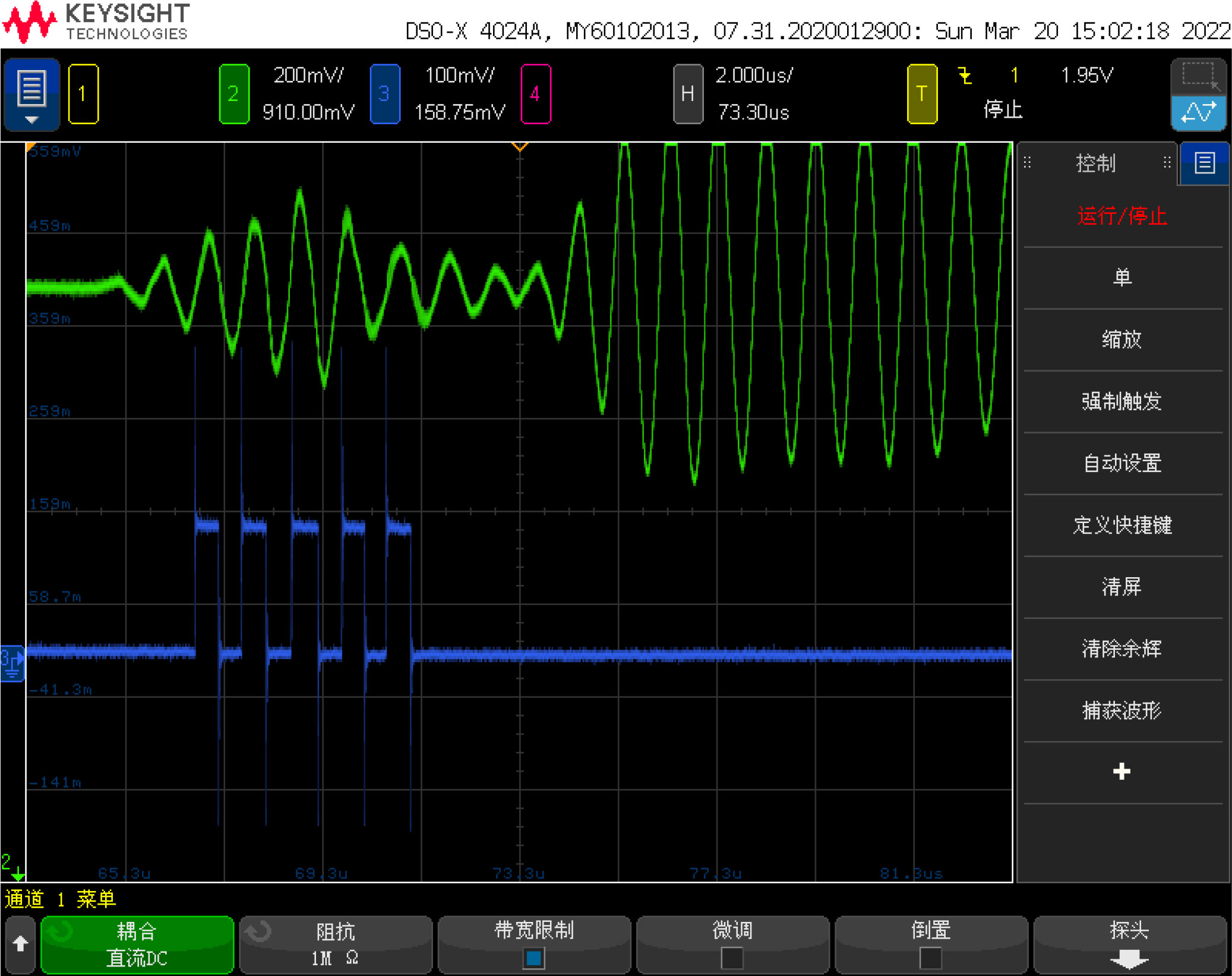
Connect the end signal line and the transducer signal line of the TDC7200. The signal waveform at the arrival time of the echo is shown in Figure 11. The upper and lower signal waveforms are the ultrasonic echo signal and the end signal respectively. It can be seen from the figure that the envelope change of the echo signal caused by the multipath effect has no obvious impact on the signal detection process, and the TDC7200 chip can correctly detect the zero-crossing point of the echo signal.
In order to measure the accuracy of the sensor, a sensor calibration experiment was carried out in a constant temperature water tank. From the introduction of the sonic speed in seawater in Chapter 1, we can see that the sonic speed in water tends to increase with temperature. When the salinity and pressure are constant, the sonic speed in water is only related to temperature. Therefore, temperature is selected as the variable to control the change of sonic speed to calibrate the sensor. Using the SVP2 temperature-salt-depth sound velocity profiler produced by VALEPORT Company as a reference, its nominal sound velocity measurement error is ±0.02m/s.
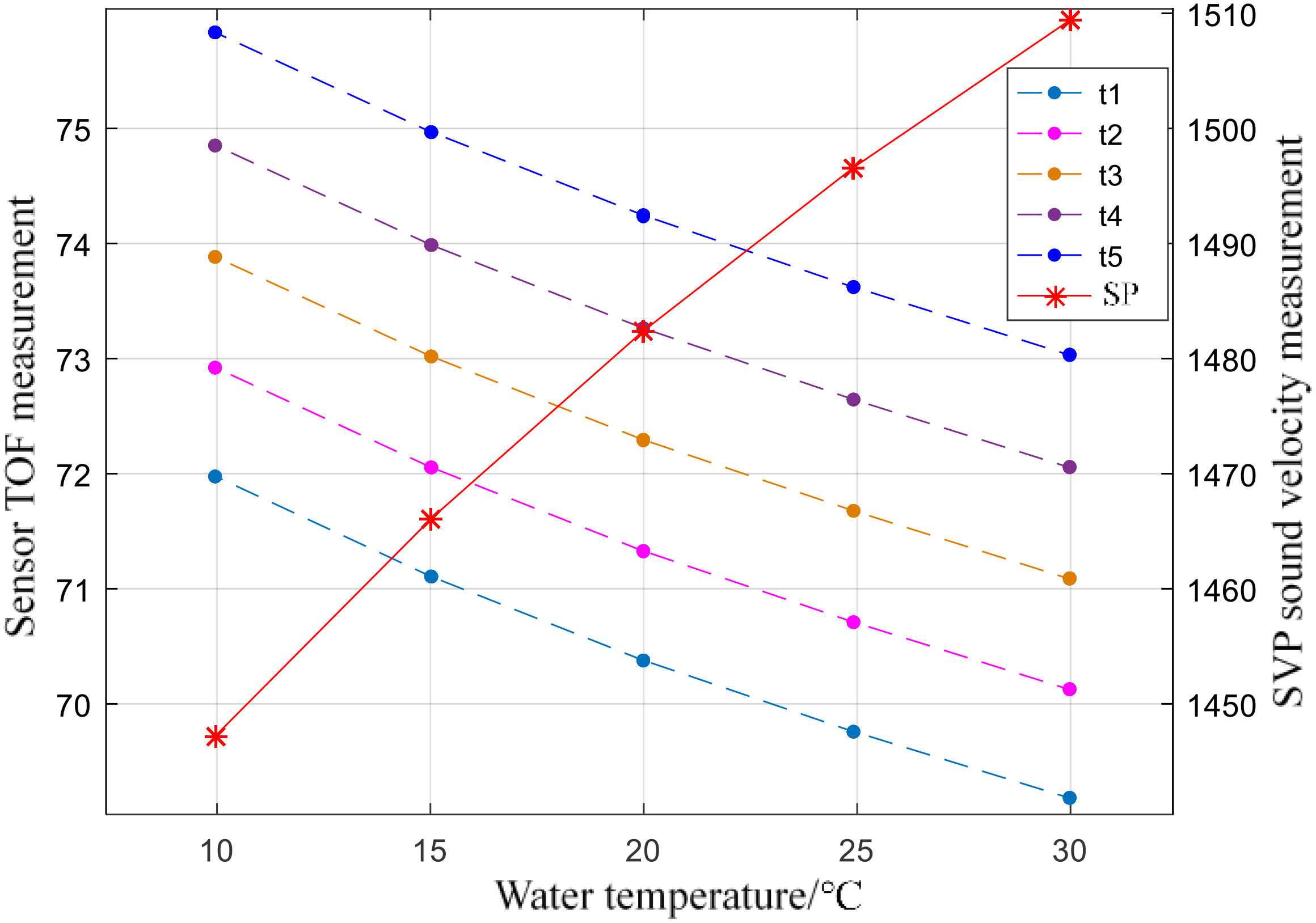
Select 30°C, 25°C, 20°C, 15°C, and 10°C as the measurement temperature. After the temperature of the water tank drops to the measurement temperature point and stabilizes, read 100 sets of readings from the two sensors through the serial port through MATLAB, and then control the water temperature to drop to the next measured temperature. Finally, the readings of the two sensors at each point are shown in Figure 12, where the sonic speed is the sound speed value (right Y-axe) measured by VALEPORT SPV2, and t1 to t5 are the five TOF moments (left Y-axe) measured by the sensor to be calibrated.
Run the neural network trained in the previous chapter by MATLAB, and calculate the sound velocity value output by the time difference measured by the sensor after being calibrated by the neural network. As a control, the regression line of the reciprocal of the sound velocity value measured by the SVP2 profiler and the average value of the five zero-crossing points was calculated using the least squares method. The fitting results are shown in Equation 4, where Vcf is the output result of the linear fitting.
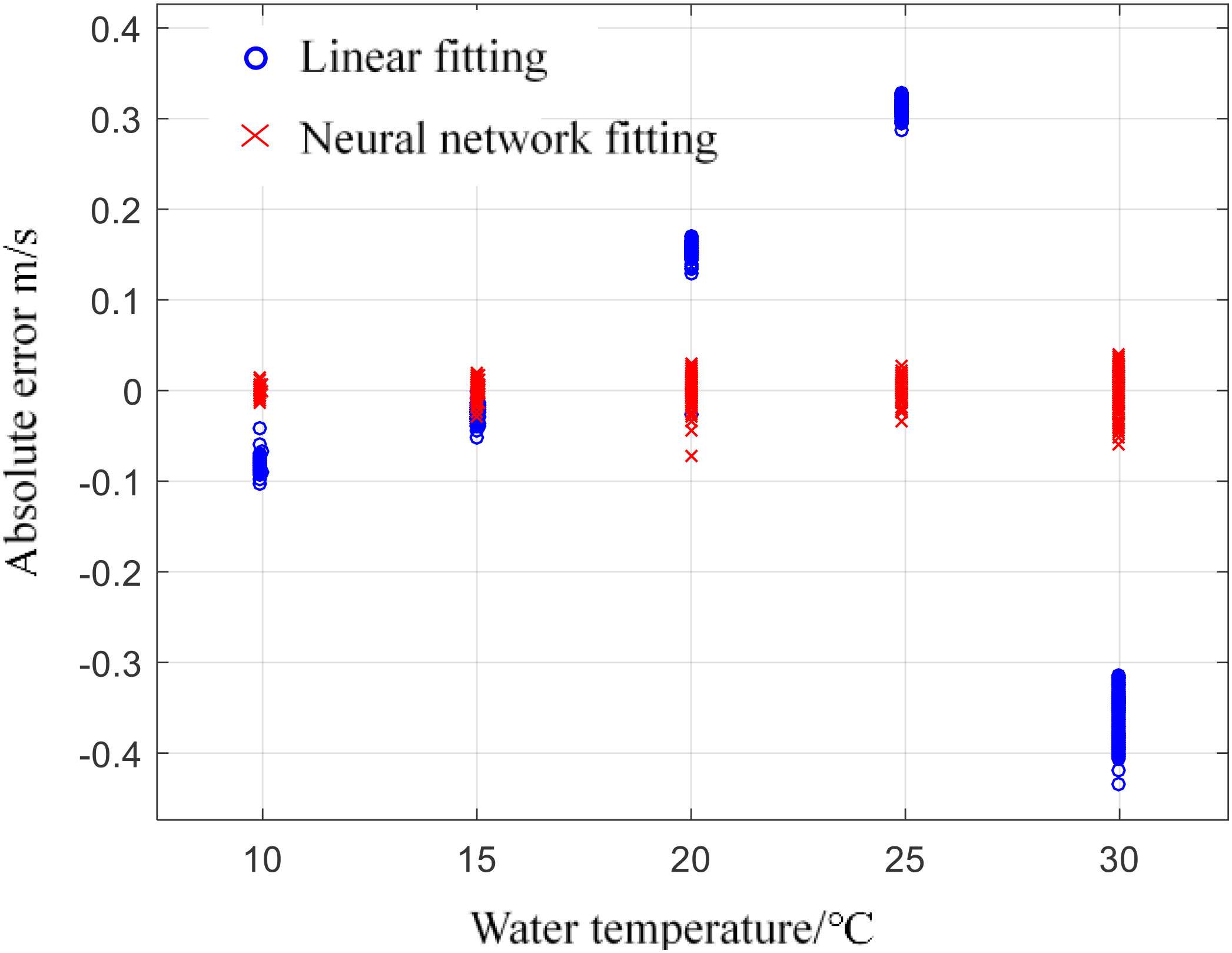
Taking the mean value of 100 times the sonic speed measured by SVP as the reference value, the 100 sets of data measured at each temperature are brought into the neural network and Equation 3 for calculation. The error between the neural network output result and the linear regression fitting result is shown in Figure 13. The averages of the results of neural network calibration and linear regression calibration at each temperature point are compared, as shown in Table 2. Combining Figure 13 and Table 2, it can be seen that the output of the neural network is closer to the SVP at the five measured temperature points, and the errors are concentrated around the zero point, and the error range is about ±0.047m/s.
It is calculated that the mean square error of the linear regression results at each measurement temperature point is 0.0553, and the standard deviation is 0.235; the mean square error of the output result after using the neural network calibration and the reference value is 0.00025, and the standard deviation is 0.0157. To sum up, the neural network method designed in this paper effectively reduces the error of the sound velocity profiler, and the final error range measured in the laboratory environment is less than ±0.05m/s, which can meet the design requirements of the system.
As shown in the Supplementary Table 1, compared with our design, most underwater sound velocity profilers are more expensive, and the corresponding accuracy improvement is not significant. It verifies that our designs enable high prediction accuracy with lower cost.
Conclusion
In this paper, a low-cost underwater sound velocity profiler is designed, and a calibration algorithm is proposed based on the sound velocity measurement principle and response characteristics of the system. The hardware system adopts a low-cost marginal design. The main control module is only responsible for data collection, interaction and storage, and does not perform data processing work, which can greatly reduce the system’s demand for hardware computing power and is suitable for large-scale deployment scenarios. Compared with the traditional linear fitting, the designed neural network calibration algorithm has better fitting and data fusion capabilities for nonlinear response curves, and can obtain measurement data with higher accuracy. In the future, the design of the probe will be improved, and the performance of the system can be further improved.
Data availability statement
The original contributions presented in the study are included in the article/Supplementary Material. Further inquiries can be directed to the corresponding authors.
Author contributions
SZ: Conceptualization, methodology, formal analysis, investigation, visualization. XX: Methodology, formal analysis, investigation. DX: Formal analysis, investigation, visualization. KL: writing-review & editing, software, visualization. CS: Supervision, data curation, project administration and funding acquisition. CT: Conceptualization, methodology, formal analysis, investigation, visualization. All authors contributed to the article and approved the submitted version.
Funding
This work was supported in part by the Major Scientific and Technologic Projects of Hainan Province under Grant ZDKJ202016, the National Natural Science Foundation of China under Grant 42076028, the High-Level Talent Project of Hainan Natural Science Foundation under Grant 2019RC236, in part by the National Natural Science Foundation of China under Grant 61861015, and in part by the Hainan Province Science and Technology Special Fund under Grant ZDKJ2021042 and Grant ZDKJ2021023.
Conflict of interest
The authors declare that the research was conducted in the absence of any commercial or financial relationships that could be construed as a potential conflict of interest.
Publisher’s note
All claims expressed in this article are solely those of the authors and do not necessarily represent those of their affiliated organizations, or those of the publisher, the editors and the reviewers. Any product that may be evaluated in this article, or claim that may be made by its manufacturer, is not guaranteed or endorsed by the publisher.
Supplementary material
The Supplementary Material for this article can be found online at: https://www.frontiersin.org/articles/10.3389/fmars.2022.996299/full#supplementary-material
References
Abiodun O. I., Jantan A., Omolara A. E., Dada K. V., Mohamed N. A., Arshadf H. (2018). State-of-the-art in artificial neural network applications: A survey. Heliyon 4 (11), e00938. doi: 10.1016/j.heliyon.2018.e00938
Akbar S. A., Shah A. S. M., Abdullah A. S., Yusof N. A.T., Khatun S., Shaharum S. M., et al. (2019). An accurate characterization of different water properties using resonant method for underwater. Proc. 10th Natl. Tech. Sem. Underwater Syst. Technol. (Singapore) 538, 113–120. doi: 10.1007/978-981-13-3708-6_10
Bela Santos A., Felisberto P., Jesus S. M. (2017). Using shipping noise for sound speed inversion in coastal areas. OCEANS (Aberdeen, UK), 1–5. doi: 10.1109/OCEANSE.2017.8085009
Chaubey A., Atre A. (2017). “A hybrid DWT-DCLAHE method for enhancement of low contrast underwater images,” in 2017 International conference of Electronics, Communication and Aerospace Technology (ICECA) (Coimbatore, India). 196–201.
Cheng H., Lou W. (2022). PD-FMCW: Push the limit of device-free acoustic sensing using phase difference in FMCW. IEEE Trans. Mobile Comput. doi: 10.1109/TMC.2022.3162631
Chen J., Zhao S., Huang Z., Qiao C. (2011). “Acoustic velocity measurement in seawater based on phase difference of signal,” in IEEE 2011 10th International Conference on Electronic Measurement & Instruments. (Chengdu China: Institute of Electrical and Electronics Engineers (IEEE)) 181–184. doi: 10.1109/ICEMI.2011.6037883
Del Grosso V. A., Made C. W. (1973). Another search for anomalies in the temperature dependence of the speed of sound in pure water. J. Acoust. Soc. America 53 (23), 561–563. doi: 10.1121/1.1913358
Didier C., Jaouad E., Gaspard G., Michel L. (2019). Real-time correction of sound refraction errors in bathymetric measurements using multiswath multibeam echosounder. OCEANS (Marseille, France), 1–7. doi: 10.1109/OCEANSE.2019.8867076
Garzetti F., Corna N., Lusardi N., Geraci A. (2021). Time-to-Digital converter IP-core for FPGA at state of the art. IEEE Access 9, 85515–85528. doi: 10.1109/ACCESS.2021.3088448
Huang W., Liu M., Li D., Yin F., Chen H., Zhou J., et al. (2021). Collaborating ray tracing and AI model for AUV-assisted 3-d underwater sound-speed inversion. IEEE J. Ocean. Eng. 46 (4), 1372–1390. doi: 10.1109/JOE.2021.3066780
Kalisz J. (2003). Review of methods for time interval measurements with picosecond resolution. Metrologia 41 (1), 17–32.
Ko N. Y., Kim T. G., Moon Y. S. (2012). Particle filter approach for localization of an underwater robot using time difference of arrival. 2012 Ocean. (Yeosu Korea), 1–7. doi: 10.1109/OCEANS-Yeosu.2012.6263573
Liu F., Chen H., Zhang L., Xie L. (2021). Time-Difference-of-Arrival-Based localization methods of underwater mobile nodes using multiple surface beacons. IEEE Access 9, 31712–31725. doi: 10.1109/ACCESS.2021.3060565
Liu C., Han K., Zhang W., Chen W. (2020). “An optimization method for sound speed profile inversion using empirical orthogonal function analysis,” in 2020 IEEE 3rd International Conference on Information Communication and Signal Processing (ICICSP) (Shanghai, China: Institute of Electrical and Electronics Engineers (IEEE)). 104–107.
Li H., Zhang L. (2021). And algorithm for self-organizing feed-forward neural networks for pattern classification. IEEE Trans. Neural Networks Learn. Syst. 32 (11), 4901–4915. doi: 10.1109/TNNLS.2020.3026114
Lv P. F., He B., Guo J. (2021). Position correction model based on gated hybrid RNN for AUV navigation. IEEE Trans. Veh. Technol. 70 (6), 5648–5657. doi: 10.1109/TVT.2021.3080134
Mikheev M. Y., Gusynina Y. S., Shornikova T. A. (2020). “Building neural network for pattern recognition,” in 2020 International Russian Automation Conference (RusAutoCon) (Sochi, Russia: Institute of Electrical and Electronics Engineers (IEEE)). 357–361. doi: 10.1109/RusAutoCon49822.2020.9208207
Rostami M. S., Saberi M., Maymandi-Nejad M., Sawan M. (2020). A low-power time-to-Digital converter for sensor interface circuits. IEEE Trans. Circuits Syst. II: Express Briefs 67 (12), 2853–2857. doi: 10.1109/TCSII.2020.2996505
Shao K., Chen J., Zhao Z., Zhang D. H. (2016). Communication: Fitting potential energy surfaces with fundamental invariant neural network. J. Chem. Phys. 145 (7), 071101. doi: 10.1063/1.4961454
Shi S. (2006). “Ad hoc wireless network based oceanic CTD measurement,” in IEEE International Conference on Information Acquisition (Veihai, China: Institute of Electrical and Electronics Engineers (IEEE)). 11–15.
Siyu E., Zhang Y. N., Han B., Zheng W., Wu Q., Zheng H. (2020). Two-channel surface plasmon resonance sensor for simultaneous measurement of seawater salinity and temperature. IEEE Trans. Instrum. Meas. 69 (9), 7191–7199. doi: 10.1109/TIM.2020.2976405
Sun S., Qin S., Hao Y., Zhang G., Zhao C. (2021). Underwater acoustic localization of the black box based on generalized second-order time difference of arrival (GSTDOA). IEEE Trans. Geosci. Remote Sens. 59 (9), 7245–7255. doi: 10.1109/TGRS.2020.3032982
Sun S., Zhang X., Zheng C., Fu J., Zhao C. (2020). Underwater acoustical localization of the black box utilizing single autonomous underwater vehicle based on the second-order time difference of arrival. IEEE J. Ocean. Eng. 45 (4), 1268–1279. doi: 10.1109/JOE.2019.2950954
Talib K. H., Othman M. Y., Sulaiman S. A. H., Wazir M. A.M., Azizan A. (2011). Determination of speed of sound using empirical equations and SVP. IEEE 7th Int. Colloq. Signal Process. its Appl. (Penang, Malaysia), 252–256. doi: 10.1109/CSPA.2011.5759882
Wilson W. D. (1959). Speed of sound in distilled water as a function of temperature and pressure. J. Acoust. Soc. America 31 (8), 1067–1072. doi: 10.1121/1.1907828
Xue B., Wang Z., Zhang K., Zhang H., Chen Y., Jia, et al. (2018). Direct measurement of the sound velocity in seawater based on the pulsed acousto-optic effect between the frequency comb and the ultrasonic pulse. Optics Express, 26 (17), 21849–21860.
Yang L., Zhang J., Wang J. (2021). Sound speed measurement using phase estimation method of pulse signal in water. OES China Ocean. Acoust. (COA) (Harbin, China), 267–271. doi: 10.1109/COA50123.2021.9519875
Keywords: calibration, discrete wavelet transform, ranging, recurrent neural network, sound velocity profiler
Citation: Zhang S, Xu X, Xu D, Long K, Shen C and Tian C (2022) The design and calibration of a low-cost underwater sound velocity profiler. Front. Mar. Sci. 9:996299. doi: 10.3389/fmars.2022.996299
Received: 17 July 2022; Accepted: 18 October 2022;
Published: 10 November 2022.
Edited by:
JongJin Park, Kyungpook National University, South KoreaReviewed by:
Peng Ren, China University of Petroleum (East China), ChinaYongwei Liu, Harbin Engineering University, China
Copyright © 2022 Zhang, Xu, Xu, Long, Shen and Tian. This is an open-access article distributed under the terms of the Creative Commons Attribution License (CC BY). The use, distribution or reproduction in other forums is permitted, provided the original author(s) and the copyright owner(s) are credited and that the original publication in this journal is cited, in accordance with accepted academic practice. No use, distribution or reproduction is permitted which does not comply with these terms.
*Correspondence: Keliu Long, a2VsaXVsb25nQGhhaW5hbnUuZWR1LmNu; Chong Shen, Y2hvbmdzaGVuQGhhaW5hbnUuZWR1LmNu; Chuan Tian, dGlhbmNAaWRzc2UuYWMuY24=
 Shengzong Zhang1,2
 Keliu Long
 Chong Shen
 Chuan Tian