 Yanhu Chen
 Bingzhe Chen
 Meiling He1
 Luning Zhang
- 1The State Key Lab of Fluid Power and Mechatronic Systems, Zhejiang University, Hangzhou, China
- 2Ningbo Research Institute, Zhejiang University, Ningbo, China
With the increasing scarcity of energy in the world, energy has become an important part of restricting the development and application of traditional ocean profilers. The method of converting ocean thermal energy (OTE) into electrical energy through an energy conversion system is a solution. The model establishment and performance analysis of the energy conversion system are the basis of the ocean thermal profiler (OTP) design. The model and performance are affected by the coupling of multiple parameters, especially rotational speed and pressure. In this study, a universal parameterized model for multi-parameter coupling was proposed. System performance analysis based on experiments including load current, speed, mechanical efficiency and total efficiency was presented. After model parameter identification, the error of mechanical efficiency was within 5%; the total efficiency error was less than 12.8%, and the maximum efficiency point error didn’t exceed 2.21%. The results indicated that the parameterized model was satisfactory for the engineering applications and could guide the design of OTP.
1 Introduction
Profiler used for monitoring ocean profile elements are important platforms for marine scientific research. Traditional ocean profilers, such as ARGO buoys and underwater gliders, usually include many batteries. Owing to the limitations of battery capacity, they can only perform simple and short-term missions, which greatly restricts their long-term and complex applications in the ocean. In the face of energy constraints, harnessing marine renewable energy with energy conversion system is an effective solution (Khan et al., 2017; Wilberforce et al., 2019). Considering the pattern of profile motion, wave energy and tidal energy are mainly concentrated in shallow waters (Townsend, 2016; Townsend and Shenoi, 2016; Song et al., 2018); wind energy and solar energy are limited to the ocean surface and are significantly affected by weather (Tian and Yu, 2019); ocean pressure energy is related to the working depth of the profiler, which can only compensate for energy consumption (Xue et al., 2020); however, ocean thermal energy (OTE) reserves are abundant. At present, the large-scale ocean thermal energy conversion (OTEC) technology is mature, which can be generally distinguished as closed-cycle, open-cycle and hybrid cycle (Huang et al., 2003). In the closed-cycle structure, the ejector refrigeration cycle and spray flash evaporation desalination unit realize desalination and refrigeration (Zhou et al., 2021). The OTEC has been effectively applied in the energy and freshwater supply of the island (Osorio et al., 2016). The researches of large-scale OTEC indicate that OTE is widely distributed and has a stable structure. Compared to other types of marine renewable energy sources, OTE is more suitable for ocean profilers.
An ocean thermal profiler (OTP) can capture and utilize OTE. Compared with direct driving by OTE, the method of converting OTE into electrical energy through an energy conversion system to drive is safer and more reliable. Two categories of energy conversion system can be classified according to the power generation principles. (1) Using thermoelectric generators (TEGs) to convert OTE into electrical energy directly (Buckle et al., 2013; Falcão Carneiro and Gomes de Almeida, 2018); (2) using solid-liquid phase change materials (PCMs) to capture OTE, and then convert it into electrical energy through an energy conversion system. The energy conversion system is mainly composed of a hydraulic motor and a generator. Owing to its compact structure and high energy-density ratio, it more suitable for OTP and has been widely applied. SOLO-TREC (Chao, 2016), Slocum-TREC (Haldeman et al., 2015) and SL1 (15) are equipped with energy conversion system to provide energy supply, which greatly increased the voyage and sampling frequency.
The performance study of the energy conversion system through modelling can provide important support for the design, motion control, and energy optimization of the OTP. Currently, most studies have concentrated on the conversion system of wind energy, wave energy, tidal energy, and hydraulic energy (Chen et al., 2020; He et al., 2020). Fan et al. studied the modelling and control of a hybrid wind-tidal turbine with an accumulator. A hydraulic transmission device was used to integrate and transmit the captured energy. The hydraulic accumulator balanced output power and demand by storing and releasing excess energy. Finally, they developed and integrated a mathematical model of the system (Fan et al., 2016). Walter Gil-González et al. established a dynamic model for small hydro-power plant, and designed a controller based on passivity theory which better than PI controller (Gil-González et al., 2020). Wei et al. proposed a new type of closed hydraulic wind turbine with an energy storage system and demonstrated the parametric design and modelling of a 600 kW hydraulic wind turbine using a Micon 600 kW wind turbine as an example (Wei et al., 2018). Chan Roh et al. established a mathematical model for the hydraulic system of floating wave energy converters, which included an accumulator, hydraulic motor, and generator. The proposed maximum power control algorithm based on the model increased the output power by 18% (Roh et al., 2021). Wang et al. established a mathematical model for the key components of the hydraulic energy storage and conversion system of a wave energy converter, which provided theoretical guidance for optimizing the energy conversion efficiency (Wang and Lu, 2018). Jónsdóttir et al. proposed a stochastic models of the short-term variability for wave energy and tidal energy based on the Irish system, which indicated that tidal generation leads to larger frequency variations than those that are caused by wind generation (Jónsdóttir and Milano, 2020). Zhang et al. proposed an electro-hydraulic energy collection damper for off-road vehicles, which could convert the vibration of a reciprocating suspension into one-way rotation of the generator, and they mathematically deduced the dynamic model of the system. Simultaneously, an experimental test proved the effectiveness of its energy collection capacity (Zhang et al., 2017). Ho et al. proposed a new hydraulic closed-loop hydrostatic transmission energy-saving system and developed a hydraulic pump/motor efficiency model for speed, displacement, and differential pressure. The maximum energy recovery efficiency was 66% (Ho and Ahn, 2010).
However, research on the modelling of energy conversion systems for the OTP has been scarce. Owing to the nonlinear characteristics, Xia et al. applied the neural network method to identify and model the energy conversion system of the OTP and obtained the curved surface of the efficiency on the inlet pressure of the hydraulic motor and the load current of the generator (Xia et al., 2020). Wang et al. established a comprehensive energy conversion efficiency model of the OTP, developed a system prototype OTEC, and successfully completed a sea trial. The converted energy initially met the energy requirements of the OTEC (Wang et al., 2019).
Above research has mostly ignored the actual working conditions of energy conversion systems for OTP, especially the change in the mechanical efficiency and the total efficiency with the rotation speed and pressure; thus, performance study is not comprehensive. In this paper, the factors affecting the performance of energy conversion system are analyzed according to the operation principle of OTP. A universal parameterized model of the total efficiency for the energy conversion system are proposed. The performance analysis is presented by establishing an experimental platform. Simultaneously, experimental data are used to identify parameters of the parameterized model and verify the accuracy.
The remainder of this paper is organized as follows. Section 2 introduces the operation principle of OTP, analyses the affecting factors of performance and presents an experimental platform. In Section 3, the parameterized model of the energy conversion system is established. In Section 4, performance analysis and experimental verification are presented. Section 5 provides a brief conclusion.
2 System overview and experimental platform
2.1 System overview
The OTP collects data of the ocean’s vertical profile by moving up and down while capturing OTE and generating electricity to power sensors, controllers, GPS, and other electronic equipment. The OTP is mainly composed of a thermal engine, energy conversion system, buoyancy adjustment system, data acquisition and communication systems, control system, and a pressure hull. The thermal engine, buoyancy adjustment system, and energy conversion system jointly realize OTP movement and power generation. The thermal engine was encapsulated with PCM to capture the OTE. When the OTP is in warm water, the volume of the PCM increases and external work is performed to convert OTE into potential energy and store it in the accumulator. The energy conversion system is mainly composed of a hydraulic motor, generator, and battery, which can convert the potential energy of the accumulator into electrical energy.
Figure 1 shows the energy conversion and operation principle of the OTP, which is mainly divided into four stages. (1) The water surface stage: the OTP stays on warm water, the PCM melts and expands, and the oil in the thermal engine is pumped into the accumulator to realize OTE capture. (2) The sinking stage: the buoyancy adjustment system regulates oil return from the external bladder to the internal bladder so that the buoyancy decreases and the OTP sinks. (3) The deep water stage: the OTP is located in cold water, the PCM solidifies and shrinks, and the oil in the internal bladder is sucked into the thermal engine. (4) The rising stage: the oil in the accumulator enters the external bladder through the hydraulic motor so that the buoyancy becomes larger and the OTP rises. Simultaneously, the hydraulic motor drives the generator to generate electricity and store electric energy in the battery.
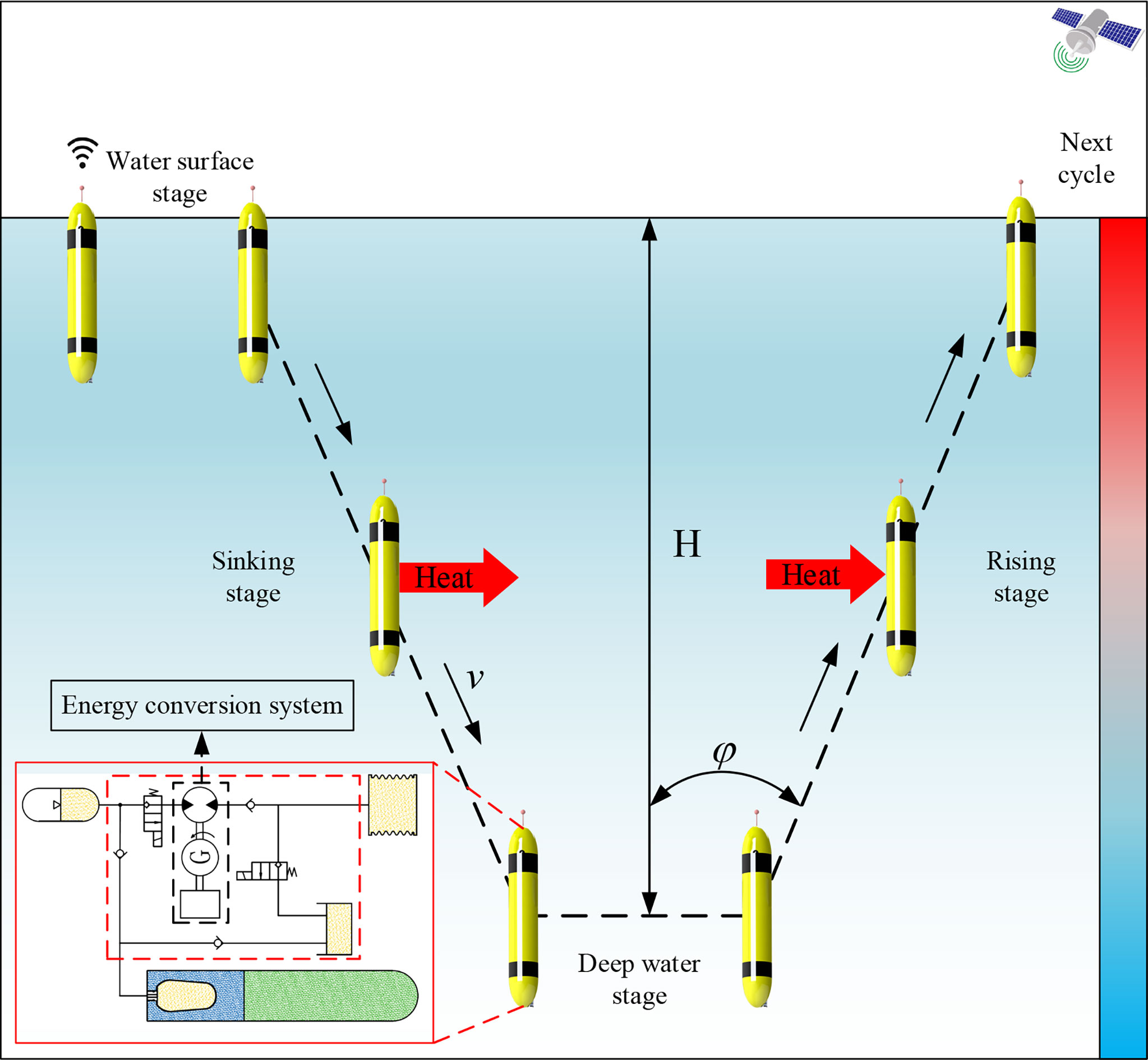
Figure 1 The principle of the operation and the energy conversion for the OTP.
The energy conversion system adopts an energy storage power generation mode. According to the operation principle of the OTP, the energy conversion system is characterized by the following. (1) In a single profile, the total amount of OTE stored by the accumulator is certain; (2) the hydraulic motor inlet pressure follows the accumulator pressure and gradually decreases; and (3) the outlet pressure of the hydraulic motor changes with the pressure of the external bladder, which is the water pressure during power generation. Therefore, the performance of energy conversion system is affected by the coupling of multiple parameters. The parameters of the hydraulic motor include inlet pressure, outlet pressure, displacement, and speed. The parameters of the generator include the power, voltage, armature resistance, speed constant, torque constant, and reducer. In practical applications, it was found that the mechanical efficiency of the hydraulic motor was significantly affected by the speed, and the traditional mechanical efficiency model was not suitable for the energy conversion system of the OTP. When the hydraulic motor and generator are determined, the performance of energy conversion system is mainly affected by the pressure, speed and load current.
2.2 Experimental platform
According to system overview of the OTP, the experimental platform for the energy conversion system is designed and shown in Figure 2. The pump station provides a pressure source for the energy conversion system and can adjust the inlet pressure of the hydraulic motor to maintain stable pressure. A relief valve was set between the outlet of the hydraulic motor and the oil return port of the pump station to form the outlet pressure and simulate the seawater pressure. The hydraulic motor and generator were connected through torque and speed sensors to monitor the changes in torque and speed during power generation. Flow meters and pressure sensors were installed at the inlet and outlet of the hydraulic motor to collect the pressure and flow. The output of the generator is connected to a programmable electronic load that adopts the constant-current mode to adjust the load current of the generator. The computer controlled the electronic load to change the load current of the generator to adjust the speed of the hydraulic motor.
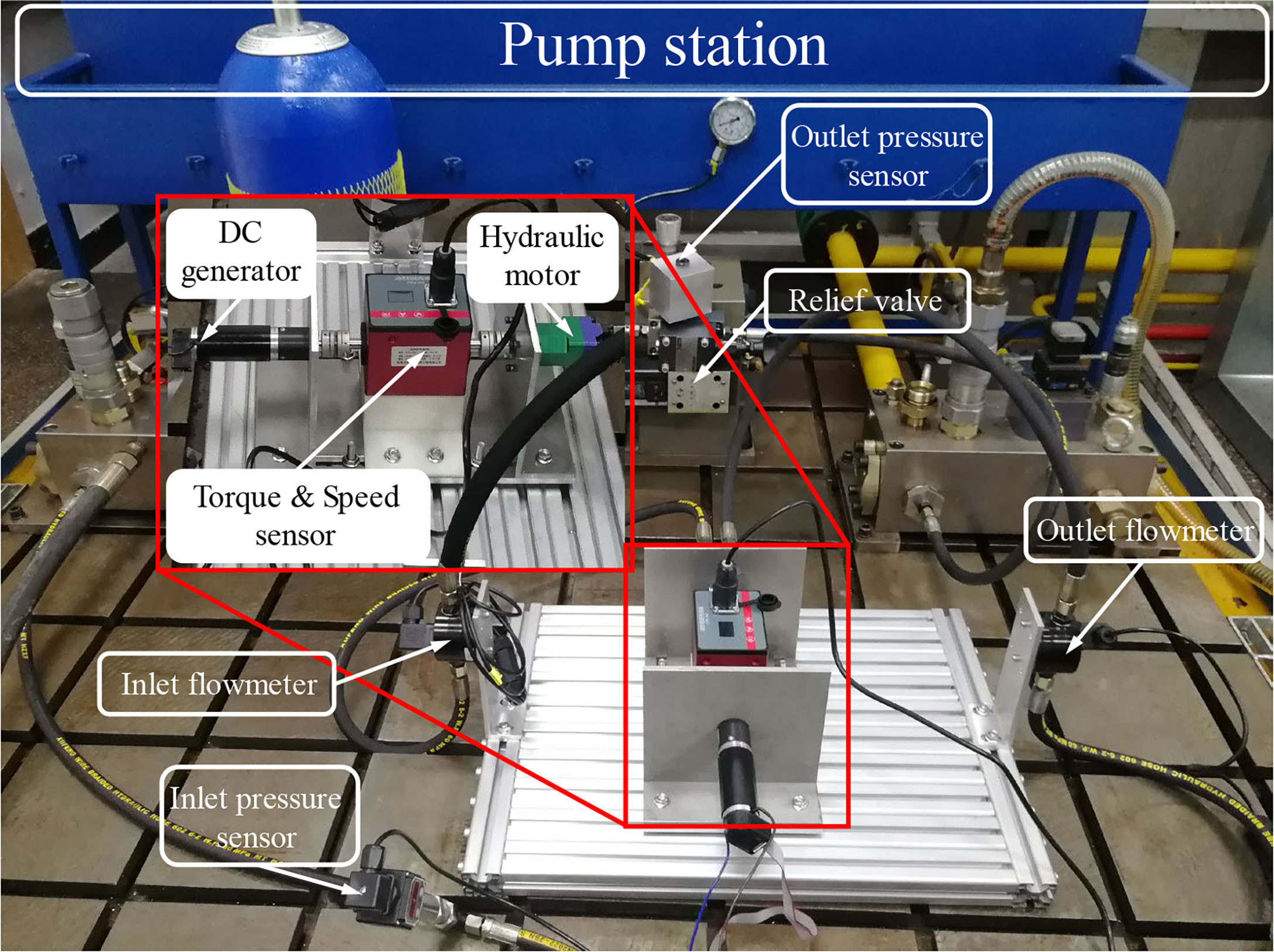
Figure 2 The experimental platform of the energy conversion system.
The component parameters used in the experimental platform of the energy conversion system are listed in Table 1. The outlet pressure of the hydraulic motor was set at 5 MPa to simulate the seawater pressure. Under each fixed pressure during the experiment, the controller controlled the speed of the hydraulic motor rising from 300 rpm to 2000 rpm while controlling and collecting data every 50 rpm.
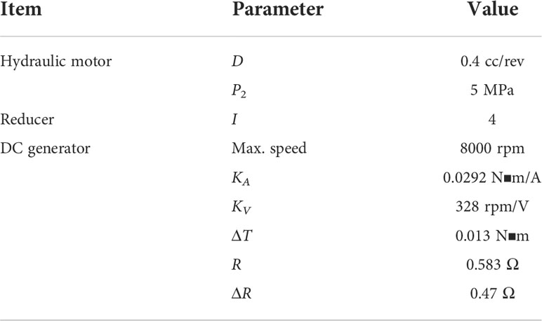
Table 1 The component parameters used in the experimental platform of energy conversion system.
3 Mathematical modelling
3.1 Hydraulic motor model
A hydraulic motor is a hydraulic actuator that converts hydraulic energy into rotational mechanical energy. It is one of the core components of energy conversion systems. The swashplate axial piston hydraulic motor has the advantages of a high working pressure, high working speed, and compact structure. It is suitable for the highly integrated energy conversion system of the OTP.
The working principle and force analysis of the swashplate axial piston hydraulic motor are shown in Figure 3. The high-pressure oil with an inlet pressure P1 enters the bottom of the plunger through the flow distribution window of the port plate to push the plunger outwards and cause the slippers to press against the swash plate. The acting force FN is decomposed into the axial component force Fz balanced with the hydraulic pressure of the plunger and the force Fy perpendicular to the axis of the plunger. Fy forms torque on the axis of the cylinder block and drives the cylinder block to rotate against the load. The effect of the outlet pressure P2 is similar to that of the inlet pressure, but it acts as a hindrance.
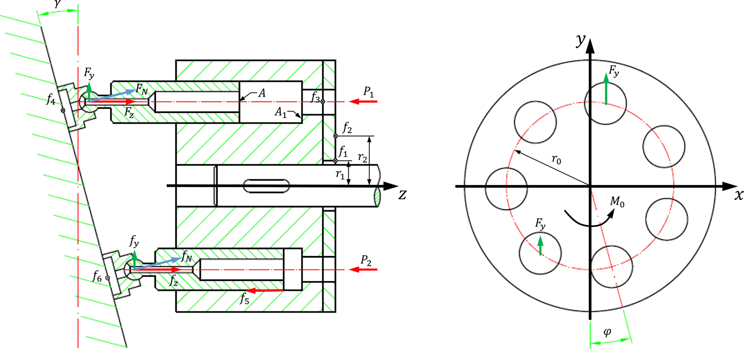
Figure 3 The working principle and force analysis of the swashplate axial piston hydraulic motor.
The number of plungers Z of the hydraulic motor is mostly odd, which reduces the flow non-uniformity coefficient. Therefore, there are two scenarios for the number of plungers connecting the high-pressure oil of the port plate.
where φ is the rotation angle of the deepest plunger embedded in the cylinder block relative to the bottom dead centre and α is the angle between two adjacent plungers.
3.1.1 The mechanical efficiency model
Mechanical efficiency is a parameter used to evaluate the degree of mechanical loss in a hydraulic motor. The friction loss of the swashplate axial piston hydraulic motor is mainly caused by the relative motion of the friction pair between the bottom surface of the cylinder block and port plate, between the slippers and swashplate, and between the plunger and plunger cavity. The mechanical efficiency of the hydraulic motor is expressed as follows:
where Tt is the theoretical torque, Tp is the practical torque, and Tloss is the friction-loss torque.
According to the force analysis shown in Figure 2, Tt and Tloss can be deduced (Ke et al., 2006; Yongqiang, 2008; Tianliang and Yueying, 2012).
(1) The force of the inlet and outlet pressure oil is transmitted to the swash plate through the plunger and slipper, and the average torque is produced by the reaction force generated by the swash plate on the output shaft. The average torque is Tt.
where M0 is the instantaneous friction torque on the output shaft caused by the reaction force generated by the inlet and outlet pressure oil transmitted to the swash plate, A is the cross-sectional area of the plunger, γ is the inclination angle of the swash plate, r0 is the radius of the plunger distribution circle, P1 is the inlet pressure of the hydraulic motor, P2 is the outlet pressure of the hydraulic motor, ΔP is the pressure difference between the inlet and outlet of the hydraulic motor, and D is the displacement of the hydraulic motor.
(2) Average friction torque T1 of the output shaft owing to friction generated by the radial force of the bearing
where M1 is the instantaneous friction torque produced by the friction generated by the radial force of the bearing on the output shaft, r1 is the action radius of friction f1 , and μ1 is the friction factor of the action surface of friction f1 .
(3) The average friction torque T2 of the friction generated by the axial force of the bearing on the output shaft is
where M2 denotes the instantaneous friction torque produced by the friction generated by the axial force of the bearing on the output shaft, r2 denotes the action radius of friction f2 , and μ2 denotes the friction factor of the action surface of friction f2 .
(4) The average friction torque T3 of the output shaft caused by the friction between the bottom surface of the cylinder block and the port plate is given by
where M3 is the instantaneous friction torque transmitted to the output shaft by the friction generated between the bottom surface of the cylinder block and port plate, μ3 is the friction factor of the friction f3 action surface, and A1 is the action area of the pressure oil in the cylinder bore.
(5) The average friction torque T4 of the output shaft caused by friction between the swash plate and sliding shoe is given as follows.
where M4 is the instantaneous friction torque transmitted to the output shaft by the friction generated between the swash plate and slipper, μ4 is the friction factor between the swashplate and slipper, and c1 is the transmission coefficient of the friction torque generated by friction f4 to the output shaft.
(6) The average friction torque T5 of the friction generated by the centrifugal force of the plunger acting on the cylinder block to the output shaft is given by
where M5 denotes the instantaneous friction torque of the output shaft caused by the friction force generated by the centrifugal force of the plunger acting on the cylinder, μ5 denotes the friction factor of the action surface of the friction force f5 , m denotes the plunger mass, and n denotes the hydraulic motor speed.
Therefore, Tloss can be expressed as follows.
From equations (5)–(9), it can be seen that the friction loss of the hydraulic motor is related to the inlet pressure P1 , outlet pressure P2 , displacement D, and speed n because
Thus, Tloss can be rewritten as
where C1 , C2 , and C3 are undetermined parameters. Substituting Equations (4) and (12) into Equation (3) to obtain the mechanical efficiency model of the hydraulic motor, we obtain the following.
3.1.2 The volumetric efficiency model
The power loss caused by the internal and external leakage of the liquid, including the internal leakage of the working chamber volume due to the compressibility of the liquid, is expressed in terms of volumetric efficiency as follows.
where qV is the actual flow, qVt is the theoretical flow, and Δq is the internal leakage flow of liquid in the hydraulic motor.
Substituting Equation (16) into Equation (15) to obtain the volumetric efficiency model of the hydraulic motor, we obtain
where CV is the differential pressure leakage coefficient of the hydraulic motor and μoil is the dynamic viscosity of the hydraulic oil.
3.2 The energy conversion system model
Qt is the theoretical input flow of the hydraulic motor, and the theoretical input power Pin of the hydraulic motor is given as follows.
where Tdrive is the driving torque output of the hydraulic motor and is calculated using the following equation.
The hydraulic motor was connected to the DC generator through the reducer. The mechanical resistance torque ΔT and electromagnetic resistance torque Tem generated by the generator form a dynamic balance with the hydraulic motor driving torque. The torque balance equation is as follows:
where i is the transmission ratio of the reducer, KA is the torque coefficient of the generator, and I is the generator output current. Substituting Equation (20) into Equation (19), we obtain the output current of the generator as follows.
The output voltage of the DC generator U is calculated as follows.
where KV is the speed constant of the generator, R is the armature resistance of the generator and ΔR is the contact resistance of the generator. Therefore, the power of generator Pout is given as follows.
The efficiency model of energy conversion system ηtotal can be obtained as follows.
4 Performance analysis and parameters identification
The performance analysis of the energy conversion system based on the experiment complements the parameterized model. Due to the nonlinearity of the parameterized model, the relationships of the intermediate variables after parameter identification are difficult to obtain directly, such as the load current. However, the speed is controlled by the load current. Therefore, analyzing the performances of load current, speed, and efficiency contributes to the original design of the OTP.
4.1 Performance analysis
4.1.1 Load current and speed
Figure 4 shows the results of the load current varies with inlet pressure of hydraulic motor. The maximum and minimum load current increase with the inlet pressure. The slope of the minimum load current is much gentler than that of maximum load current, thereby narrowing the variation range of load current. More obviously, the range of load current is 0-2.26 A when the inlet pressure is 15 MPa, while it is 7.61-8.04 A when the inlet pressure is 28 MPa.
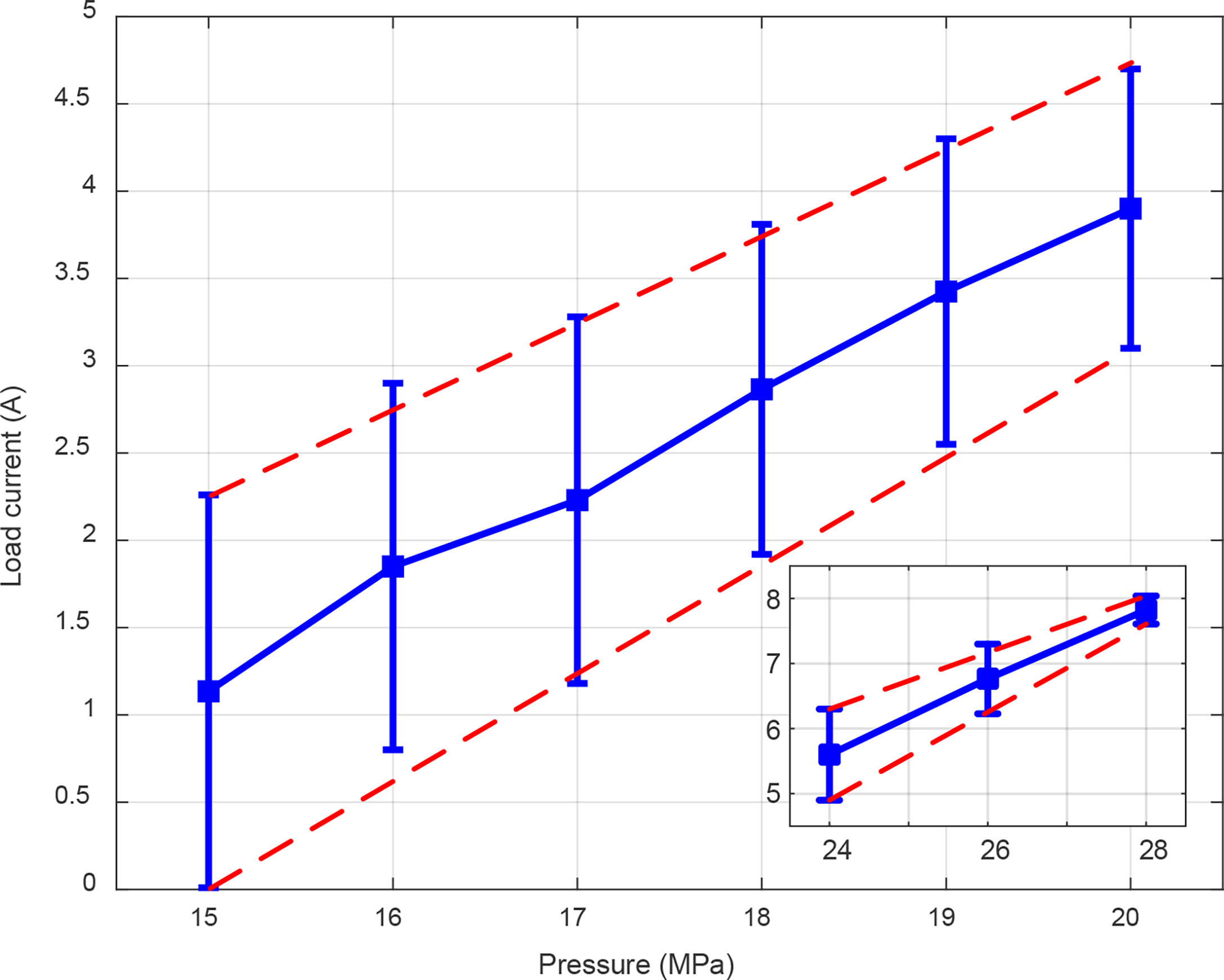
Figure 4 Load current varies with inlet pressure of hydraulic motor.
The speed and load current are not independent. Figure 5 shows the relationship between speed and load current. The results show that the load current is inversely related to the speed under the same inlet pressure. From equation (20), it can be concluded that the larger the load current, the higher the electromagnetic resistance torque; in turn, the speed decreases. When the speed is fixed, the load current increases with the inlet pressure. The reason for the performance is the large inlet pressure makes the hydraulic motor output more torque, in order to achieve the same speed, a larger current is required to generate electromagnetic resistance torque. The initial value of the speed also shows a trend with the increase of the inlet pressure. The possible cause is insufficient electromagnetic resistance torque provided by the generator.
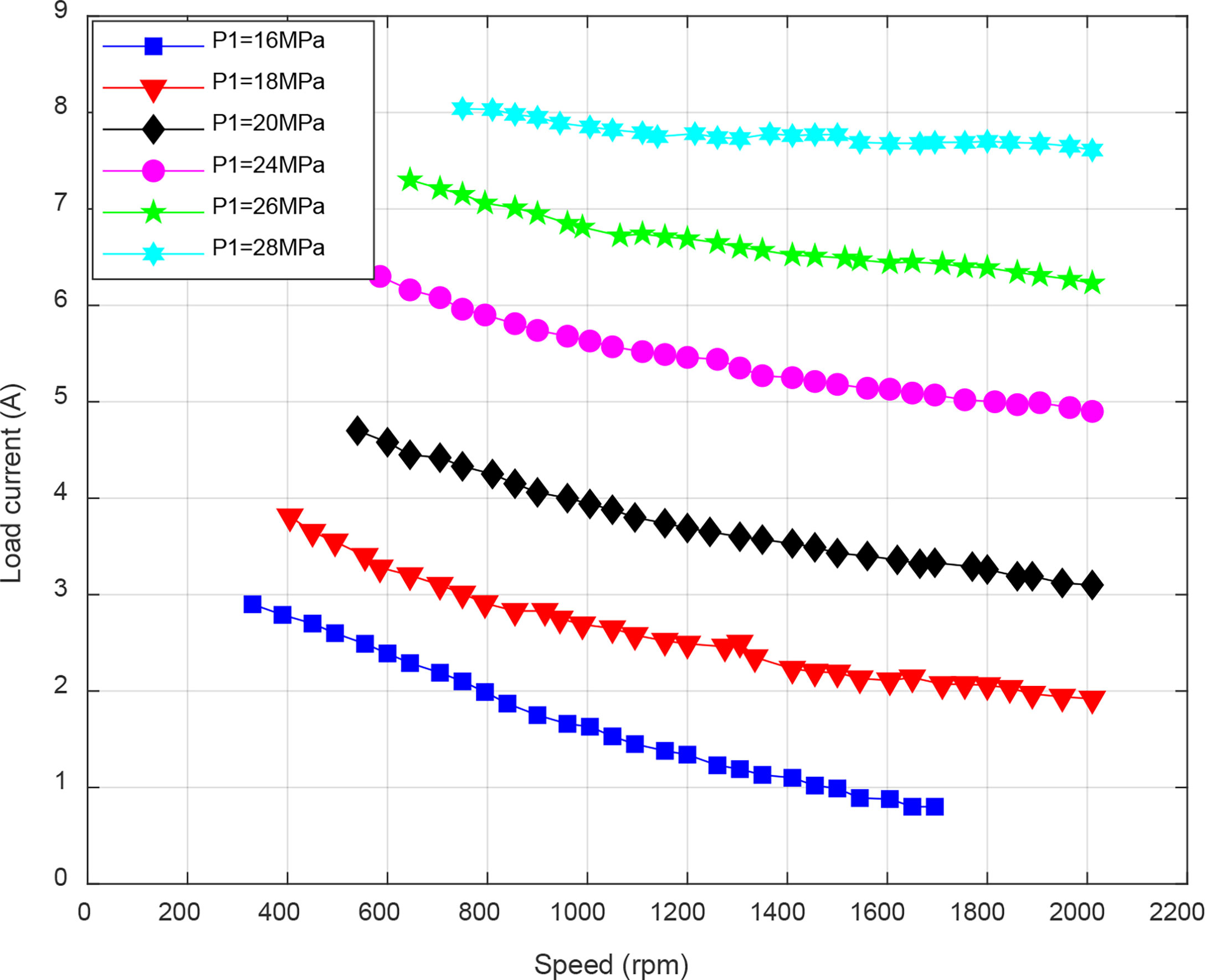
Figure 5 The relationship between speed and load current.
4.1.2 Mechanical efficiency
Figure 6 shows the results of the mechanical efficiency of hydraulic motor in the energy conversion system. The results show that the larger the speed, the lower the mechanical efficiency under the same inlet pressure. The essential reason is the same as the analysis of load current and speed in the previous part. From equation (18) to equation (20), it can be concluded that the larger the speed, the lower the torque at dynamic balance; in turn, the mechanical efficiency decreases. The mechanical efficiency increases with the inlet pressure, and the improvement is more pronounced when the inlet pressure is lower. The variation range of mechanical efficiency is inversely related to the inlet pressure, which is consistent with the conclusion of load current.
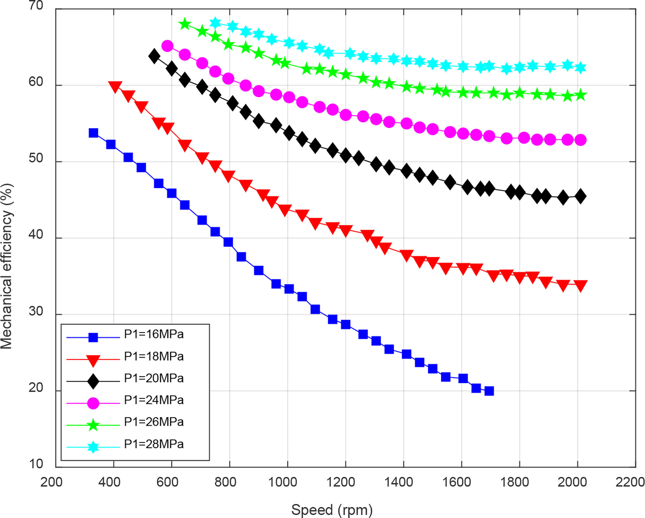
Figure 6 The mechanical efficiency of hydraulic motor in the energy conversion system.
4.1.3 Total efficiency
Figure 7 shows the total efficiency of the energy conversion system. When the inlet pressure is low, the total efficiency increases first and then decreases with the load current. As the inlet pressure increases, the total efficiency decreases with the load current, and the maximum point appears in the initial stage of power generation. The reason for the phenomenon is the limitation of the maximum speed of the generator. The maximum efficiency point of the energy conversion system also shows a rising trend with the increase of the inlet pressure. Therefore, using high-speed generator in energy conversion system can achieve maximum efficiency under high pressure.
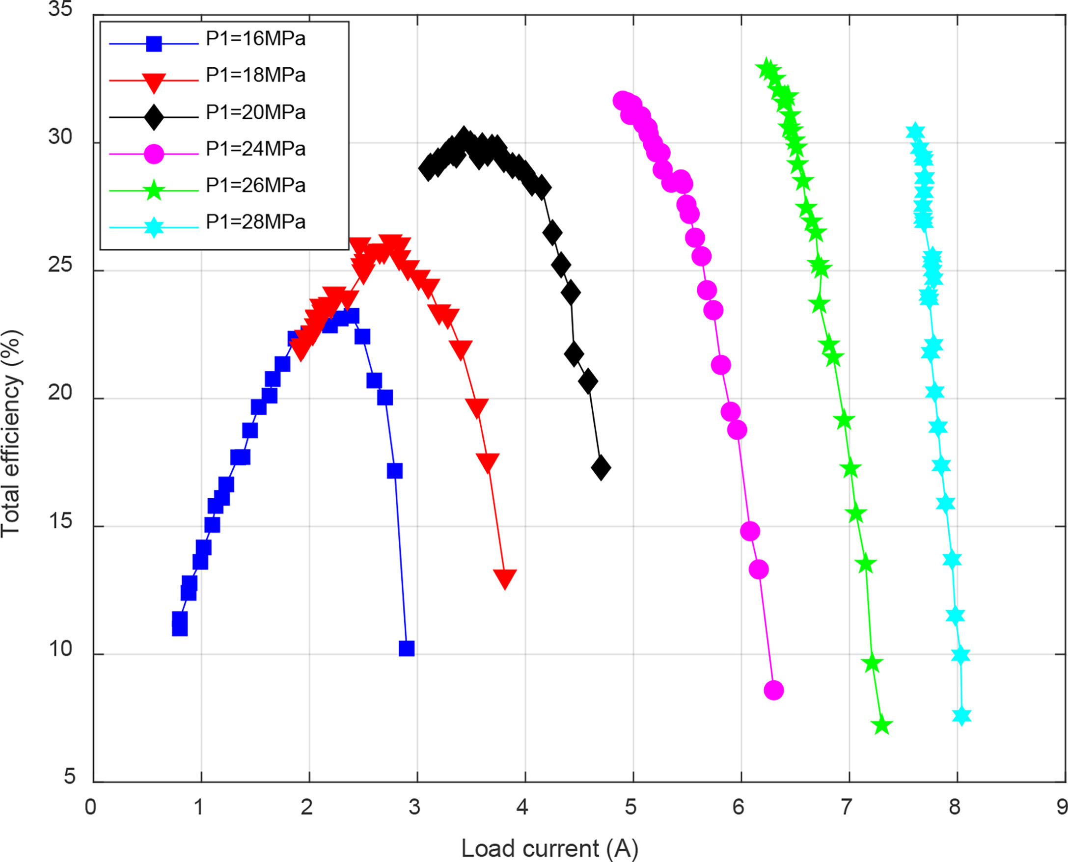
Figure 7 The total efficiency of the energy conversion system.
4.2 Parameters identification
4.2.1 Parameter identification of mechanical efficiency
The mathematical model of the mechanical efficiency of a hydraulic motor contains three undetermined parameters, and Equation (13) can be simplified as follows.
where A1 , A2 , A3 , and B1 are undetermined parameters.
The pressure difference ΔP was 10–15 MPa, and the pressure difference increment was 1 MPa. The mechanical efficiency data at different speeds under these six working conditions were obtained experimentally, and the Levenberg-Marquardt method in the nonlinear least-squares problem was used to fit Equation (25). The experimental data and fitting results are shown in Figure 8. The goodness-of-fit R2 was 0.97402, which yielded good results. The relationship between the mechanical efficiency, differential pressure, and speed is as follows.
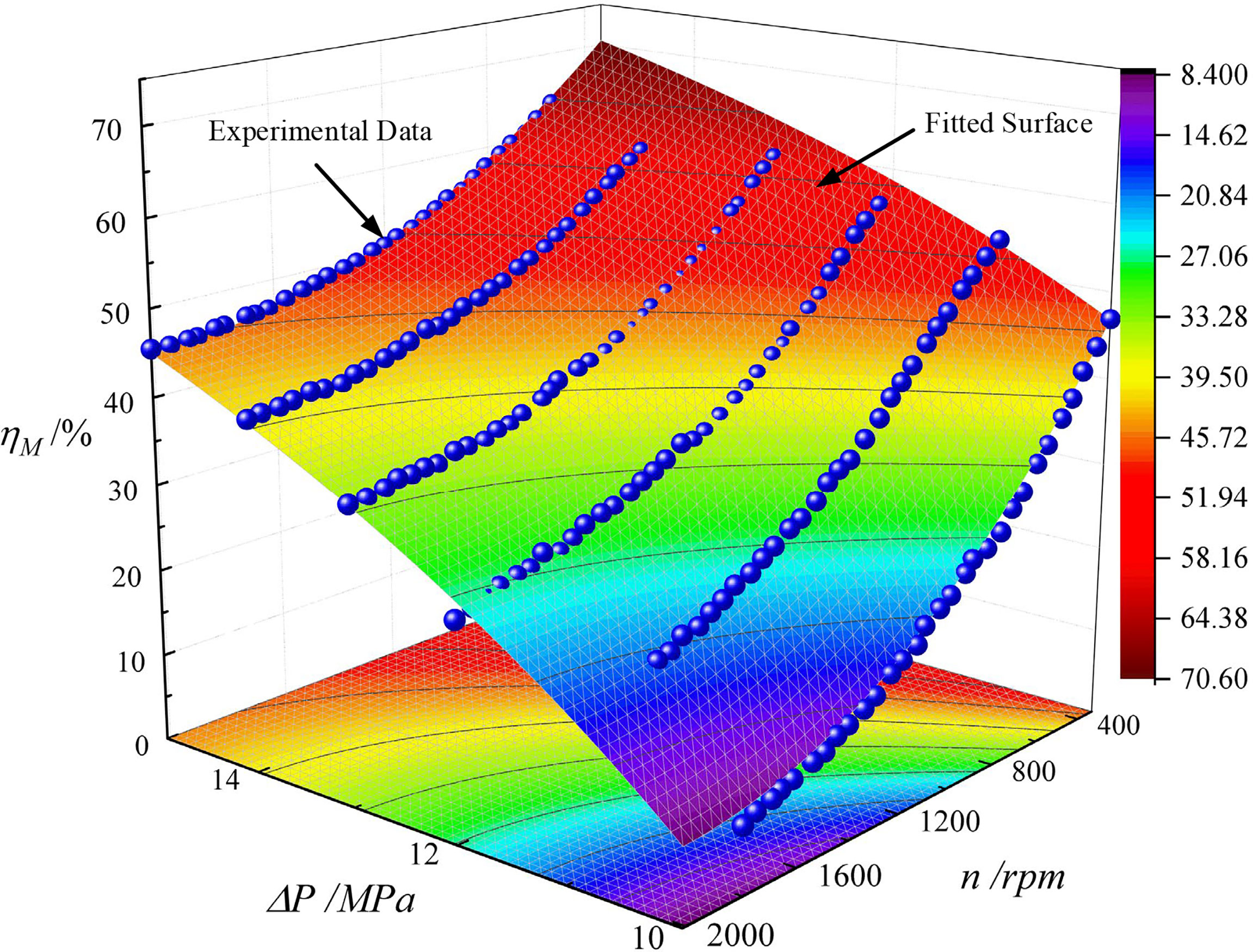
Figure 8 The experimental data and fitting results for mechanical efficiency of hydraulic motor.
Experiments with differential pressures of 19, 21, and 23 MPa were performed to verify the accuracy of Equation (26) for other pressure and speed ranges of the hydraulic motor. A comparison between the simulation and experimental results of mechanical efficiency is shown in Figure 9. Under the three verified working conditions, the average relative error between the simulated and experimental data was less than 5%, and the maximum relative error was 5.6%, verifying the effectiveness and accuracy of the mechanical efficiency parameterized model.
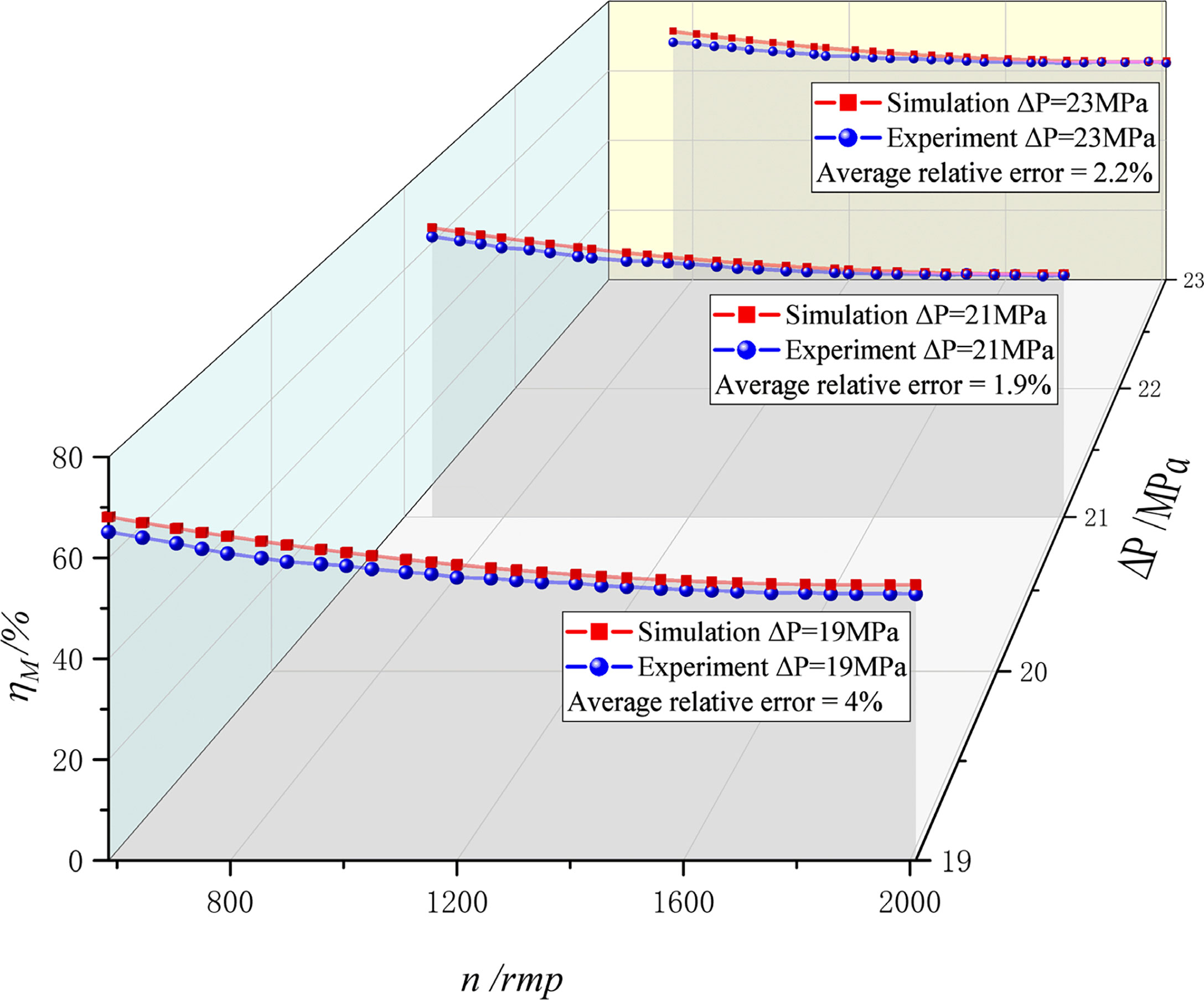
Figure 9 The comparison between the simulation and experimental results of the mechanical efficiency model.
During the experiment, there was less leakage of the hydraulic motor. Therefore, to simplify the model and calculation, it is considered that the volumetric efficiency of the hydraulic motor does not change with the pressure difference and speed.
4.2.2 Parameter identification of total efficiency
The total efficiency of energy conversion system can be derived using two methods based on the mechanical efficiency model of the hydraulic motor: (1) indirect method based on the mechanical efficiency model after parameter identification and (2) direct method based on the mechanical efficiency model before parameter identification. The indirect method can identify the unknown parameters of the intermediate variables and can be applied in the fields of dynamic modeling and control algorithm design of energy conversion system. The direct method implicitly includes unknown parameters of intermediate variables and can be applied in static modeling and energy efficiency analysis of energy conversion system.
The indirect method involves substituting Equations (26) and (21) into Equation (24). Figure 10 shows the simulation and experimental comparison of indirect method. Differential pressures of 13, 15, 19, and 21 MPa were selected for model verification. From Figure 10, it is observed that the results obtained by the model are in good agreement with the experimental results at low speeds, but they are generally greater than the experimental results at high speeds. A possible reason for this is that there is a deviation between the internal parameters of the generator and the theoretical reference value, resulting in increased frictional resistance and reduced efficiency. Furthermore, it is observed that the changing trend of the simulation results is consistent with the experimental data, and the simulation average errors are 5.7%, 4%, 12.8%, and 11.3%, respectively. Therefore, the model is valid and accurate.

Figure 10 The simulation and experimental comparison of indirect method.
The direct method involves bringing Equations (25) and (21) into Equation (24) and simplifying them to obtain a parameterized model of the total efficiency as follows.
where
b1, b2 and b3 should be separated by three lines. "ΔP2" is modified to "△P2". "D2" is modified to "D2".
Here, k1' to k13' are undetermined parameters. When the displacement and outlet pressure of the hydraulic motor remain constant, Equation (27) can be further simplified as follows.
where
k1 to k9 in the equation are undetermined parameters.
Parameter identification in the total efficiency was similar to the mechanical efficiency of the hydraulic motor. The experimental data and fitting results are shown in Figure 11. The goodness-of-fit R2 was 0.93927, indicating a good fitting result. The parameters of Equation (29) are listed in Table 2.
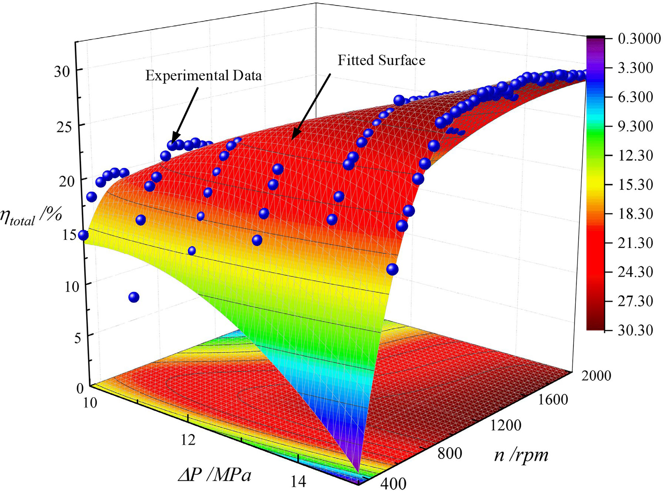
Figure 11 The experimental data and fitting results for the total efficiency of energy conversion system.
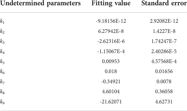
Table 2 The parameters in parameterized model of total efficiency.
The experimental data for differential pressures of 19, 21, and 23 MPa were selected to verify the parameterized model of total efficiency established by the direct method. Figure 12 shows the simulation and experimental comparison of direct method. The experimental results show that the relative error between the simulation and experiment is relatively large at the initial speed of each pressure, the relative error at other speeds is within 10%, and the average relative error between the simulation and experiment at pressure differences of 19, 21, and 23 MPa are 9%, 0.41%, and 6.75%, respectively, which verifies the validity and accuracy of the total efficiency parameterized model.
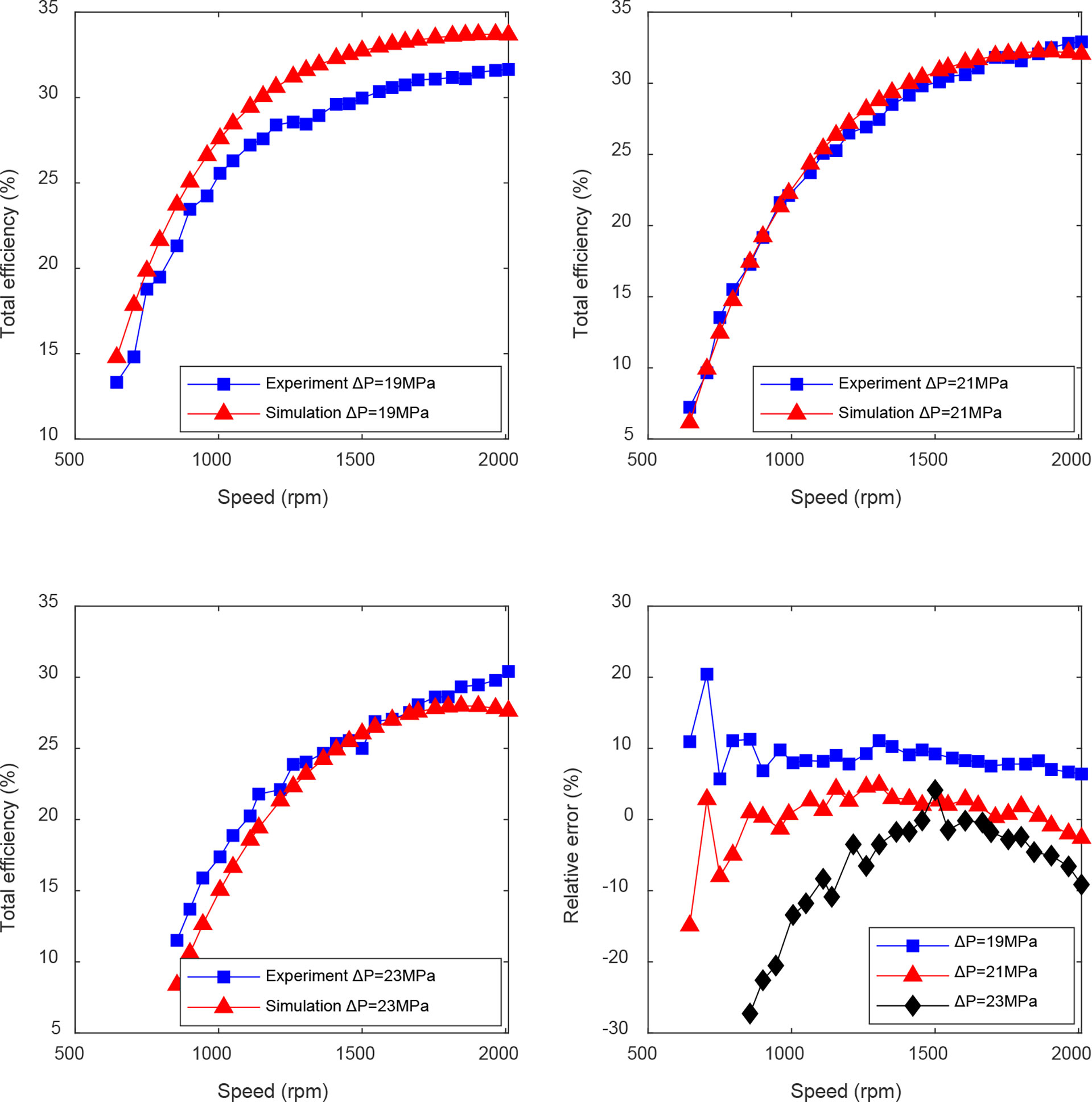
Figure 12 The simulation and experimental comparison of direct method.
The accuracy of maximum efficiency point prediction of energy conversion system is a significant criterion for judging the rationality of the proposed parameterized model. The maximum efficiency point is the optimal load current and optimal speed when the total efficiency is maximum. The load current in the direct method is an intermediate variable, which is difficult to obtain accurate parameters; therefore, the simulation and experimental comparison of the optimal load current only applies to the indirect method, while the direct method can be explained by the optimal speed indirectly. Figures 13, 14 show the experimental and simulation comparison of optimal load current and speed. In the prediction of optimal load current, the average relative error of the indirect method is 2.21%. In the prediction of optimal speed, the average relative error of indirect method is 0.45%, while that of direct method is 0.8%. The results indicate that the parameterized model of energy conversion system has a satisfactory prediction effect and meets the engineering application.
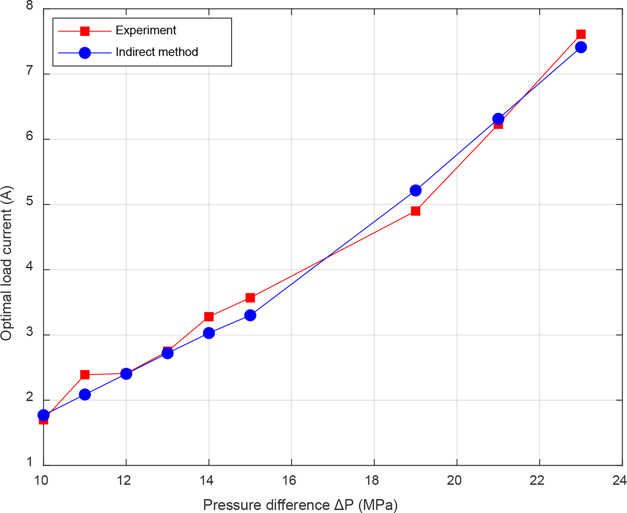
Figure 13 The simulation and experimental comparison of the optimal load current.
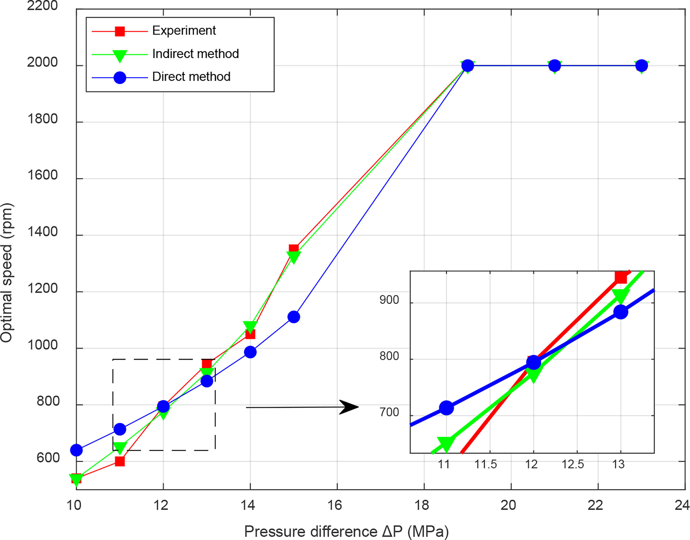
Figure 14 The simulation and experimental comparison of the optimal speed.
5 Conclusion
In this study, the factors affecting the performance of energy conversion system are analyzed according to the operation principle of OTP. A force analysis of a swashplate axial piston hydraulic motor was performed, and a parameterized model for establishing the mechanical efficiency of the hydraulic motor was established. Direct method and indirect method were proposed for establishing the universal parameterized model of total efficiency for energy conversion system. An experimental platform was established to study system performance and verify the accuracy of the proposed parameterized model.
In the energy conversion system of OTP, the maximum and minimum load current increased with the inlet pressure, but the variation range decreased. The load current was inversely related to the speed, while positively related to the inlet pressure. The mechanical efficiency of hydraulic motor increased with inlet pressure, but decreased with speed. The total efficiency increased with the load current, and decreased after reaching the maximum point at low inlet pressure, whereas the total efficiency decreased with the load current at high inlet pressure. The maximum efficiency point showed a rising trend with inlet pressure.
In the parameterized model identification, the average relative error between the simulation and experiment for the mechanical efficiency of the hydraulic motor was less than 5%, and the maximum relative error was 5.6%, verifying the validity and accuracy of the established mechanical efficiency parameterized model. For the total efficiency model established by the indirect method, the minimum average relative error was 4%, and the maximum average relative error was 12.8%. For the direct method, except for the large error at the initial speed, the average relative error in the other speed ranges was within 10%, the maximum was 9%, and the minimum was 0.41%. In the prediction of optimal load current, the average relative error of the indirect method was 2.21%. In predicting the optimal speed, the average relative errors of the indirect method and the direct method were 0.45% and 0.8%, respectively. The parameterized model of energy conversion system met the engineering application.
Data availability statement
The original contributions presented in the study are included in the article/supplementary material. Further inquiries can be directed to the corresponding authors.
Author contributions
YC, BC, QX, and CY contributed to conception and design of the study. YC provided methodology and performed the statistical analysis. BC conducted experiments, organized the database, and wrote the first draft of the manuscript. MH provided data visualization. LZ carried out the preliminary investigation. QX provided resources and supervision. CY provided project administration and funding acquisition. All authors contributed to manuscript revision, read, and approved the submitted version.
Funding
This work was supported by the National Natural Science Foundation of China (No. 51979246), National Key Research and Development Program of China (No. 2021YFC2800202), and Strategic Priority Research Program of the Chinese Academy of Sciences (No. XDA22000000).
Conflict of interest
The authors declare that the research was conducted in the absence of any commercial or financial relationships that could be construed as a potential conflict of interest.
Publisher’s note
All claims expressed in this article are solely those of the authors and do not necessarily represent those of their affiliated organizations, or those of the publisher, the editors and the reviewers. Any product that may be evaluated in this article, or claim that may be made by its manufacturer, is not guaranteed or endorsed by the publisher.
References
Available at: https://seatrec.com/news.
Buckle J. R., Knox A., Siviter J., Montecucco A. (2013). Autonomous underwater vehicle thermoelectric power generation. J. Electron Mater 42 (7), 2214–2220. doi: 10.1007/s11664-013-2584-1
Chao Y. (2016). Autonomous underwater vehicles and sensors powered by ocean thermal energy Vol. 1 (Oceans 2016 - Shanghai, IEEE).
Chen W., Wang X., Zhang F., Liu H., Lin Y. (2020). Review of the application of hydraulic technology in wind turbine. Wind Energy (Chichester England) 23 (7), 1495–1522. doi: 10.1002/we.2506
Falcão Carneiro J., Gomes de Almeida F. (2018). Model and simulation of the energy retrieved by thermoelectric generators in an underwater glider. Energy convers Manage. 163, 38–49. doi: 10.1016/j.enconman.2018.02.031
Fan Y., Mu A., Ma T. (2016). Modeling and control of a hybrid wind-tidal turbine with hydraulic accumulator. Energy (Oxford) 112, 188–199. doi: 10.1016/j.energy.2016.06.072
Gil-González W., Montoya O. D., Garces A. (2020). Modeling and control of a small hydro-power plant for a DC microgrid. Electric Power Syst. Res. 180, 106104. doi: 10.1016/j.epsr.2019.106104
Haldeman C. D., Schofield O., Webb D. C., Valdez T. I., Jones J. A. (2015). Implementation of energy harvesting system for powering thermal gliders for long duration ocean research. MTS 1, 1–5. doi: 10.23919/OCEANS.2015.7404559
He X., Xiao G., Hu B., Tan L., Tang H., He S., et al. (2020). The applications of energy regeneration and conversion technologies based on hydraulic transmission systems: A review. Energy Convers Manage. 205, 112413. doi: 10.1016/j.enconman.2019.112413
Ho T. H., Ahn K. K. (2010). Modeling and simulation of hydrostatic transmission system with energy regeneration using hydraulic accumulator. J. Mech Sci. Technol. 24 (5), 1163–1175. doi: 10.1007/s12206-010-0313-8
Huang J. C., Krock H. J., Oney S. K. (2003). Revisit ocean thermal energy conversion system. Mitigation Adaptation Strat Global Change 8 (2), 157–175. doi: 10.1023/A:1026062531405
Jónsdóttir G. M., Milano F. (2020). Stochastic modeling of tidal generation for transient stability analysis: A case study based on the all-island Irish transmission system. Electric Power Syst. Res. 189, 106673. doi: 10.1016/j.epsr.2020.106673
Ke M., Ding F., Li B., Chen Z. (2006). Exploration of the influence of backing pressure on the efficiency of hydraulic motor. Nongye Jixie Xuebao (Transact Chin. Soc. Agric. Machinery) 37 (10), 127–131. doi: 10.3969/j.issn.1000-1298.2006.10.034
Khan N., Kalair A., Abas N., Haider A. (2017). Review of ocean tidal, wave and thermal energy technologies. Renewable Sustain. Energy Rev. 72, 590–604. doi: 10.1016/j.rser.2017.01.079
Osorio A. F., Arias-Gaviria J., Devis-Morales A., Acevedo D., Velasquez H. I., Arango-Aramburo S. (2016). Beyond electricity: The potential of ocean thermal energy and ocean technology ecoparks in small tropical islands. Energy Policy 98, 713–724. doi: 10.1016/j.enpol.2016.05.008
Roh C., Ha Y., Shin S., Kim K., Park J. (2021). Advanced maximum power control algorithm based on a hydraulic system for floating wave energy converters. Processes 9 (10), 1712. doi: 10.3390/pr9101712
Song R., Dai Y. M., Qian X. (2018). Intermittent wave energy generation system with hydraulic energy storage and pressure control for stable power output. J. Mar. Sci. Technol. 23 (4), 802–813. doi: 10.1007/s00773-017-0512-4
Tianliang L., Yueying Y. (2012). Research on the efficiency of bent axis hydraulic piston motor. Fluid Power Transm. Control 6, 18–23.
Tian B., Yu J. (2019). Current status and prospects of marine renewable energy applied in ocean robots. Int. J. Energy Res. 43 (6), 2016–2031. doi: 10.1002/er.4371
Townsend N. (2016). In situ results from a new energy scavenging system for an autonomous underwater vehicle Vol. 1 (Oceans 2016 mts/ieee Monterey, IEEE).
Townsend N. C., Shenoi R. A. (2016). Feasibility study of a new energy scavenging system for an autonomous underwater vehicle. Auton Robots 40 (6), 973–985. doi: 10.1007/s10514-015-9506-4
Wang D., Lu K. (2018). Design optimization of hydraulic energy storage and conversion system for wave energy converters. Prot. Control Modern Power Syst. 3 (1), 1–9. doi: 10.1186/s41601-018-0080-6
Wang G., Yang Y., Wang S., Zhang H., Wang Y. (2019). Efficiency analysis and experimental validation of the ocean thermal energy conversion with phase change material for underwater vehicle. Appl. Energy 248, 475–488. doi: 10.1016/j.apenergy.2019.04.146
Wei L., Liu Z., Zhao Y., Wang G., Tao Y. (2018). Modeling and control of a 600 kW closed hydraulic wind turbine with an energy storage system. Appl. Sci. 8 (8), 1314. doi: 10.3390/app8081314
Wilberforce T., El Hassan Z., Durrant A., Thompson J., Soudan B., Olabi A. G. (2019). Overview of ocean power technology. Energy (Oxford) 175, 165–181. doi: 10.1016/j.energy.2019.03.068
Xia Q., Chen Y., Yang C., Chen B., Muhammad G., Ma X. (2020). Maximum efficiency point tracking for an ocean thermal energy harvesting system. Int. J. Energy Res. 44 (4), 2693–2703. doi: 10.1002/er.5055
Xue G., Liu Y., Si W., Ji C., Guo F., Li Z. (2020). Energy recovery and conservation utilizing seawater pressure in the working process of deep-argo profiling float. Energy (Oxford) 195, 116845. doi: 10.1016/j.energy.2019.116845
Yongqiang G. (2008). Analysis on efficiency of axial piston motor. Hoisting Conveying Machinery 2008 (7), 51–54. doi: 10.3969/j.issn.1001-0785.2008.07.017
Zhang Y., Chen H., Guo K., Zhang X., Eben Li S. (2017). Electro-hydraulic damper for energy harvesting suspension: Modeling, prototyping and experimental validation. Appl. Energy 199, 1–12. doi: 10.1016/j.apenergy.2017.04.085
Keywords: ocean thermal profiler, energy conversion system, mathematical modelling, efficiency, performance analysis
Citation: Chen Y, Chen B, He M, Zhang L, Xia Q and Yang C (2022) Performance study of energy conversion system for ocean thermal profiler. Front. Mar. Sci. 9:996204. doi: 10.3389/fmars.2022.996204
Received: 17 July 2022; Accepted: 11 August 2022;
Published: 30 August 2022.
Edited by:
Shaowei Zhang, Institute of Deep-Sea Science and Engineering, Chinese Academy of Sciences (CAS), ChinaCopyright © 2022 Chen, Chen, He, Zhang, Xia and Yang. This is an open-access article distributed under the terms of the Creative Commons Attribution License (CC BY). The use, distribution or reproduction in other forums is permitted, provided the original author(s) and the copyright owner(s) are credited and that the original publication in this journal is cited, in accordance with accepted academic practice. No use, distribution or reproduction is permitted which does not comply with these terms.
*Correspondence: Qingchao Xia, bXluYW1laXN4aWFAemp1LmVkdS5jbg==; Canjun Yang, eWNqQHpqdS5lZHUuY24=