 Zhengyong Liu
 Shengqi Zhang
 Chengkun Yang1
 Weng-Hong Chung
- 1Guangdong Provincial Key Laboratory of Optoelectronic Information Processing Chips and Systems, School of Electronics and Information Technology, Sun Yat-sen University, Guangzhou, China
- 2Southern Marine Science and Engineering Guangdong Laboratory (Zhuhai), Zhuhai, China
- 3Photonics Research Center, Department of Electrical Engineering, The Hong Kong Polytechnic University, Kowloon, Hong Kong, SAR, China
Ocean observation becomes increasingly important as the ocean climate changes diversely and the marine disasters (such as tsunamis, typhoon, and earthquakes) occur frequently, which typically requires widespread and reliable monitoring techniques. In such a scenario, this paper presents a submarine optical fiber sensing system to realize real-time monitoring of the environmental parameters. The system consists of an undersea optical interrogation module together with multiple fiber Bragg grating (FBG)-based sensors, particularly for the measurement of depth, vibration, and temperature. The experimentally demonstrated sensitivities of the pressure, temperature, and vibration sensors are -1.993 nm/MPa, 0.08 nm/°C, and 0.139 nm/g (g = 9.8 m/s2), corresponding to the resolutions of 0.25 kPa, 0.006°C, and 0.004 g, respectively, based on the interrogation resolution of ~0.5 pm. To verify the feasibility and reliability of the proposed submarine sensing system, a prototype was developed and a proof test under the sea was conducted in an area close to Pearl River Estuary in China. The achieved results from the sea test show promising accuracy that is comparable to the commercially available electric-based sensors. Good characteristics of the surface water wave were observed by conducting the fast Fourier transform of the measured depth change, which shows a dominant frequency of ~0.25 Hz. The system provides the flexibility of replacing various optical fiber sensors easily and the capability of real-time monitoring in a remote way. The demonstrated submarine sensing system could find potential applications in real-time monitoring of the undersea ecosystem and the environmental evolution where multiparameter sensing is in demand.
Introduction
Ocean observation becomes vitally important due to the close relationship between marine ecology and human life. The variation of environmental parameters such as temperature, depth, salinity, and vibration in a specific region is a key vector to evaluate the change in the local ocean environment, which typically influences the balance of the undersea ecosystem and the climate. Full characterization of these physical parameters in a wide range could help to establish the geophysical model in an attempt to understand the evolution of the ocean (Favali and Beranzoli, 2006). Some specific chemical sensing system can even contribute to investigate the substance cycling and the ecosystem around the hydrothermal plume (Gartman and Findlay, 2020). As extreme weather occurs frequently on the sea and causes disasters to coastal areas, it is of great significance to have real-time monitoring of the undersea environmental change. To achieve this, basically, a full monitoring network is required to map the physical parameters and build an effective forecast mechanism.
In recent years, various approaches have been proposed to realize monitoring of the submarine environment. There are several well-developed cabled seafloor observatories established to monitor the multiparameters under the sea, for instance, the NEPTUNE in Canada, MARs in the United States, ESONET in Europe, S-NET in Japan, etc. All of these undersea observatories are based on sophisticated measurement systems on the seabed and connected by submarine optical cables. Among them, the high-precision sensing system plays an important and irreplaceable role. Basically, most sensing system integrates various electrical sensors, which provide high sensitivity to certain measurands. The sensing performance depends on the materials and mechanical structure of the sensors. Since 2012, a Joint Task Force (JTF) on SMART cable systems chaired by Howe et al. (2019) was established to realize ocean and climate monitoring and disaster warning utilizing the submarine telecommunication optical cables. The main feature of such a system is to integrate individual electrical temperature, vibration, and pressure sensors into the repeater, which therefore works as a multiparameter sensing element on the seabed. Owing to the wide and long-distance network of the submarine cables, full characterization of the ocean environment and dynamics could be achieved (Howe et al., 2022).
In addition to electrical sensing approaches, optical fiber sensing technique becomes increasingly feasible in monitoring of marine information due to its advantages of low cost, compactness, immunity to electromagnetic interference and corrosion, long-distance capability, and easy compatibility to the optical communication system. In 2018, Marra et al. (2018) reported on laser interferometry via submarine optical cables and achieved monitoring of earthquakes. The vibration caused the slight change in the optical phase of the fiber-based interferometer. Such submarine monitoring system is beneficial to the use of existing optical cables. A similar approach was proposed by Zhan et al. (2021) in 2021, where the state of the polarization (SOP) was monitored to retrieve the seismic wave occurring along the optical cable. The advantage of such interferometry is its high sensitivity to microseism, which however lacks precise localization. To further achieve localization of a particular event, the distributed acoustic sensing (DAS) system was proposed using existing submarine dark fibers, which is proven efficient to monitor undersea vibrations caused by earthquakes, ocean waves, and microseisms (Jousset et al., 2018; Ajo-Franklin et al., 2019; Williams et al., 2019; Walter et al., 2020). This distributed approach is promising to construct a cable-based sensing network easily and realize monitoring of ocean dynamics, as existing submarine optical cables can be employed in an ultralow cost. One possible shortage of it may be the sensing capability of only vibration, which could be complemented by various sensors.
To achieve the multiparameter measurement, various optical fiber sensors of high performance have been investigated. By employing the architecture of fiber Bragg grating (FBG) or fiber interferometry, temperature, pressure, vibration, and even chemical parameters could be measured with high precision and resolution. The sensing systems consisting of those sensors have been employed successfully in structural health monitoring in industries of railway (Liu et al., 2017), oil and gas (Qiao et al., 2017), biomedical engineering (Najafzadeh et al., 2020), and civil engineering (Wu et al., 2021). To achieve high sensing performance, sensing configurations based on the detection of either the spectral wavelength (Leitão et al., 2021) or the optical intensity (Leal-Junior et al., 2018; Leal-Junior et al., 2019) are proposed. The proper enhancement of the demodulation techniques provides an improvement of the sensing accuracy. Regarding ocean information monitoring, the sensing performance in terms of sensitivity, accuracy, and limit of detection typically varies with the sensor structures (Min et al., 2021). Undersea pressure is one key parameter to obtain depth information, which is relevant to the sea surface height and tsunamis (Yu, 2015). Optical fiber pressure sensors have been developed with various sensitivities from ~0.004 nm/MPa (Xu et al., 1993) up to ~50 nm/MPa (Liu et al., 2018) by measuring the optical spectral shift with respect to pressure change. By varying the structure of the fiber interferometer, simultaneous measurement of temperature and pressure or salinity in a single sensor can be achieved (Zhao et al., 2019; Zhao et al., 2022a). A similar fiber interferometer was also reported by micromachining an in-line cavity to realize temperature and salinity sensing (Flores et al., 2019). Basically, optical fiber sensors provide full flexibility in measuring seawater parameters. However, most optical fiber sensors are demonstrated in laboratory tests and few are employed to monitor submarine environmental changes due to harsh conditions and requirements of strict sensing systems.
As a demonstration of the sea test, Wang et al. (2020) in 2020 developed an FBG sensor array along the marine optical cable and laid the cable undersea to monitor temperature and depth. The FBG sensors worked efficiently and provided profiling with high spatial resolution owing to the densely distributed pressure and temperature sensors. In this sensing scheme, the signal demodulation system is on the boat, meaning that the submarine part is passive. In another verification of the sea test, researchers from Ireland developed a compact optical fiber sensing system containing an FBG-based sensor and managed to measure temperature, depth, and salinity (Duraibabu et al., 2017). The sensing system was mounted on a remotely operated vehicle (ROV). From these field tests, it can be seen that the undersea optical fiber sensors show high potential in multiparameter monitoring of the marine environment. However, the capability of the sensors and the relevant undersea sensing system is still under investigation, especially to improve the sensitivity and accuracy of the specific sensors as well as the compatibility of the sensing system with the optical communication system.
In this paper, we report a submarine optical fiber sensing system integrated with pressure, temperature, and vibration sensors to realize real-time monitoring of the undersea environment. The sensing system contains an undersea interrogation module to demodulate the optical sensing signal. Various optical fiber sensors could be connected to the system to establish the local monitoring network and eventually acquiring multiple parameters widely in real time. The demonstrated sensitivities of the pressure, temperature, and vibration sensors are -1.993 nm/MPa, 0.08 nm/°C, and 0.139 nm/g (g = 9.8 m/s2), corresponding to the resolutions of 0.25 kPa, 0.006°C, and 0.004 g, respectively, if taking the interrogation resolution of 0.5 pm into account. The proposed optical fiber sensing system was proof-tested under the sea, and the monitored results are comparable to the commercial electrical sensors installed on-site. In contrast to the conventional underwater electric-based sensors, the novelty of the proposed submarine sensing system is that the system has flexible capability of multiplexing various FBG-based sensors by a simple connection and the measurands obtained by the sensors can be monitored in real-time via optical fiber cable. The proposed submarine sensing system could find potential applications in real-time monitoring of the undersea ecosystem and the environmental evolution where multiparameter sensing is highly required.
Materials and Methods
Principle and Development of the Optical Fiber Sensors
The proposed temperature, pressure, and vibration sensors are developed based on the principle of FBG, which basically is sensitive to the perturbations caused by the external strain and temperature change. The strain can be induced by any mechanical stress exerted on the fiber such as pressure and vibration. In principle, FBG works as a filter to reflect back a specific wavelength propagating in the fiber core if a broadband incident light is launched into the optical fiber. As illustrated in Figure 1A, there is a dominating peak showing in the reflection spectrum, indicating that the wavelength at the peak is totally reflected while the other wavelengths transmit continuously to the end. The reflected wavelength, also called Bragg wavelength (λB), is determined via the phase-matching condition as expressed by (Erdogan, 1997):
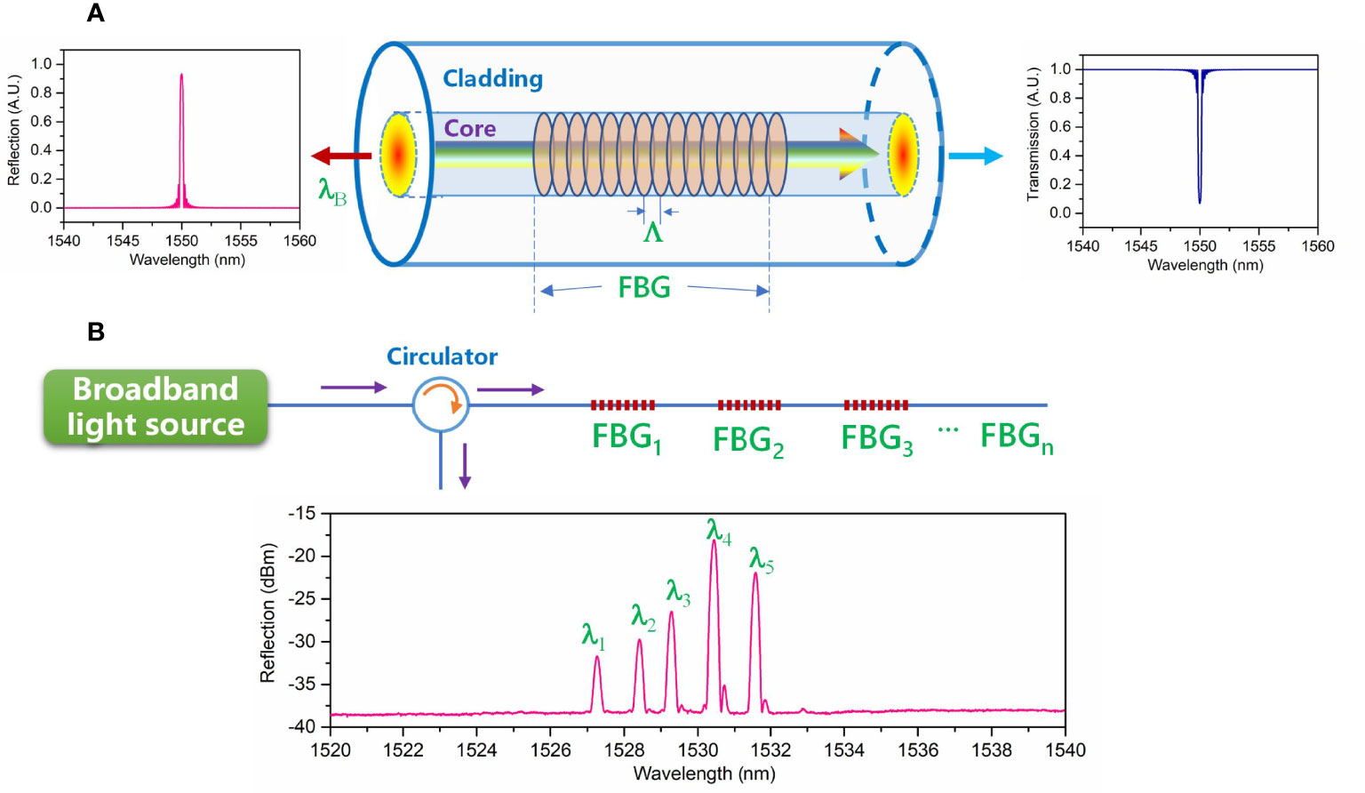
Figure 1 Schematic illustration of (A) working principle of the optical fiber Bragg grating (FBG) and (B) multiplexing principle of various FBG-based sensors.
where neff is the effective refractive index of the fundamental mode propagating in the fiber core, and Λ is the pitch of the FBG. By fabricating the FBGs with different pitches in a strand of fiber, the refection spectrum shows various peaks, each of which corresponds to a certain FBG, as illustrated in Figure 1B. To inscribe the FBG in the core of the optical fiber, the standard phase-mask technique with 248-nm UV laser scanning (Cheng et al., 2003; Pospori et al., 2017) was utilized in this work. Such inscription method has been demonstrated to be reliable and repeatable during volume production, also suitable for the grating inscription of polymer optical fibers (Marques et al., 2013; Marques et al., 2018). After inscription, the refractive index of the core is modulated by the UV laser depending on the pitch of the phase mask used. The grating length depends on the design of the sensor, varying from a few millimeters to 10 mm.
Basically, the Bragg wavelength of FBG is a function of the refractive index of the fiber core and the grating pitch. Owing to the thermo-optic effect and photoelastic effect, the effective index and pitch can be altered by the external stress or temperature. The relationship between the Bragg wavelength change and the external measurand (i.e., temperature change: ΔT, strain: ε) can be deduced as:
where pe is the photoelastic coefficient, α is the coefficient of thermal expansion (CTE) of the fiber core, and β is the thermo-optic coefficient. In Eq. 2, η1 is the factor to describe the amount of external stress caused by pressure or vibration transferred to the strain and η2 is the transferring coefficient of thermal expansion, which are related to the particular packaging materials used to embed the FBG. These two coefficients could be determined through the calibration measurement of the sensors. Typically, the photoelastic effect is avoided to develop the temperature sensor so that only temperature change induces the Bragg wavelength shift, whereas the temperature effect cannot be reduced in the design of pressure and vibration sensors, which can only be compensated.
Interrogation Design of the Sensing System
The interrogation is necessary to demodulate the optical sensing signal that includes the change of measurands. In this work, a homemade interrogation system was designed and developed. Figure 2 shows the schematic layout of the interrogation system, including a superluminescent diode (SLD, Denselight DL-CS5169A), laser driver, interrogation module (Ibsen I-MON 512), microprocessor, power controller, optical transceiver, circulator, and coupler. The coupler is utilized to split the optical signal into four paths, each of which is able to connect to the FBG-based sensors. The wavelength range of the SLD is over 80 nm covering from 1,510 to 1,590 nm. The minimum power of the SLD is 16 mW, which is enough for the four output ports split by the coupler. The temperature and current of the SLD are controlled by the driver. An optical circulator is used to send the incident light from port 1 to port 2 and circulate the reflection light from the FBG sensors to port 3. Regarding the demodulation method of the interrogation module, it employs an array of 512 photodiodes (PDs) spaced in a line to detect the intensity of the input light. There is a blazed grating and mirror in the module that can diffract the broadband light to various components of light with different wavelengths, as illustrated in the inset of Figure 2. After accurate calibration, each PD receives the intensity of a certain wavelength. The resolution of the hardware is about 170 pm. The reflected spectral peak of one FBG typically covers a wavelength bandwidth of about 500–700 pm, meaning that about 4–5 PDs are occupied to profile the peak spectrum. As FBG is typically apodized with a Gaussian profile during fabrication (Hill and Meltz, 1997), a Gaussian peak fit algorithm is utilized in the interrogation module to achieve precise peak detection according to the arrayed intensities from the illuminated PDs. Therefore, the fitted resolution of the interrogation could reach ~0.5 pm. By detecting the peaks in the reflection spectrum of FBGs, all of the measurands can be monitored and acquired remotely in real time via the optical fiber cable and the transceiver with a speed of 100 Mbps. The power and fiber cables provide the function of electricity and communication, which could enable the submarine sensing system work independently or jointly with other systems in a network.
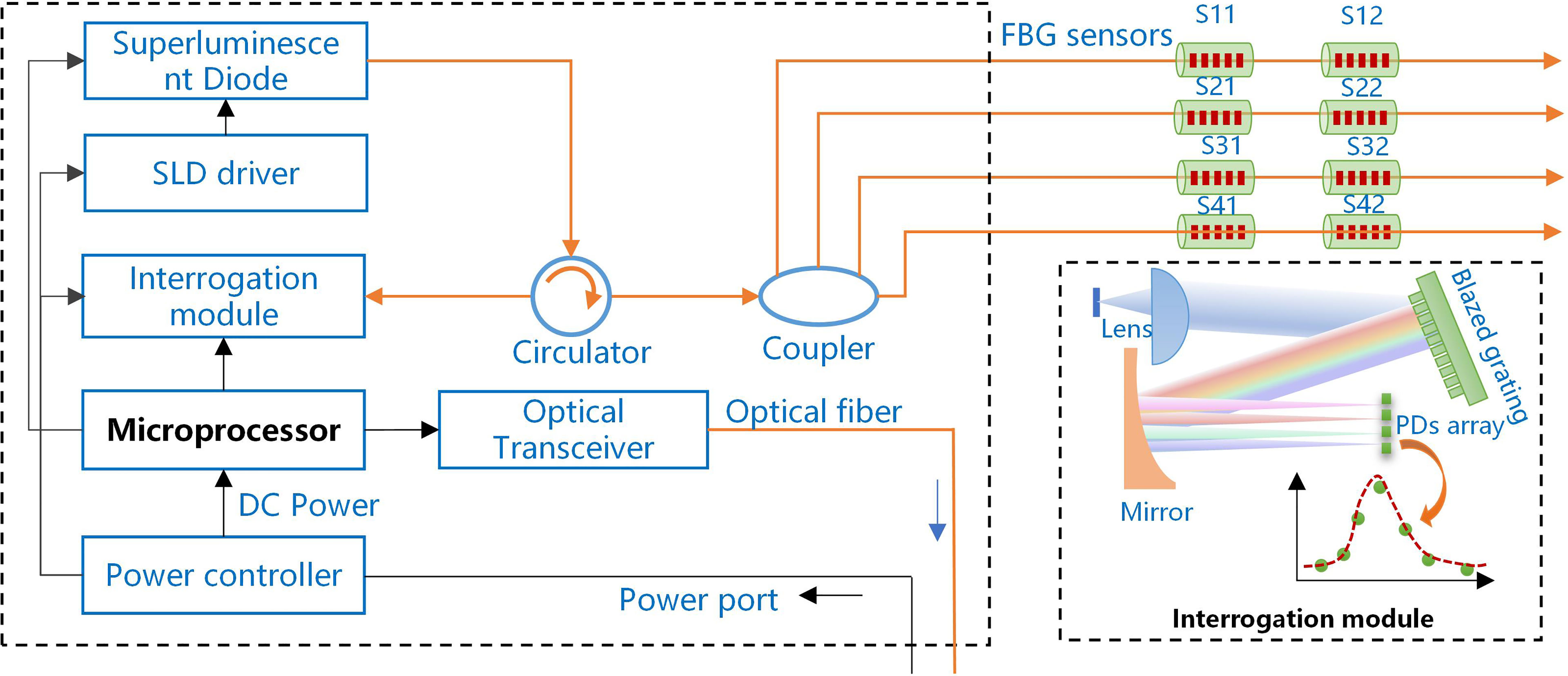
Figure 2 Schematic layout of the proposed interrogation system.
To realize and demonstrate the feasibility of the proposed submarine optical fiber sensing system, a prototype of the submarine interrogation system was developed based on the design illustrated in Figure 2. As shown in Figure 3, the entire system was designed in a cylinder made of stainless steel in an attempt to withstand high hydraulic pressure. The height, inner diameter, and outer diameter of the main body is 566, 120, and 132 mm, respectively, which however could be optimized to a smaller size by rearranging the modules inside. The main body was tested in a pressurized chamber of 15 MPa over 3 h, and no leakage was found, meaning that the system could be employed under the sea for over 1,000 m if leaving a pressure margin of one-third. Regarding the sensing capability, it is possible to carry various FBG-based sensors by connecting to the optical fiber connectors. The entire system possesses the external connection of optical fiber cable to implement the fast and real-time communication from the remote station, for instance, on the shore or the ship.
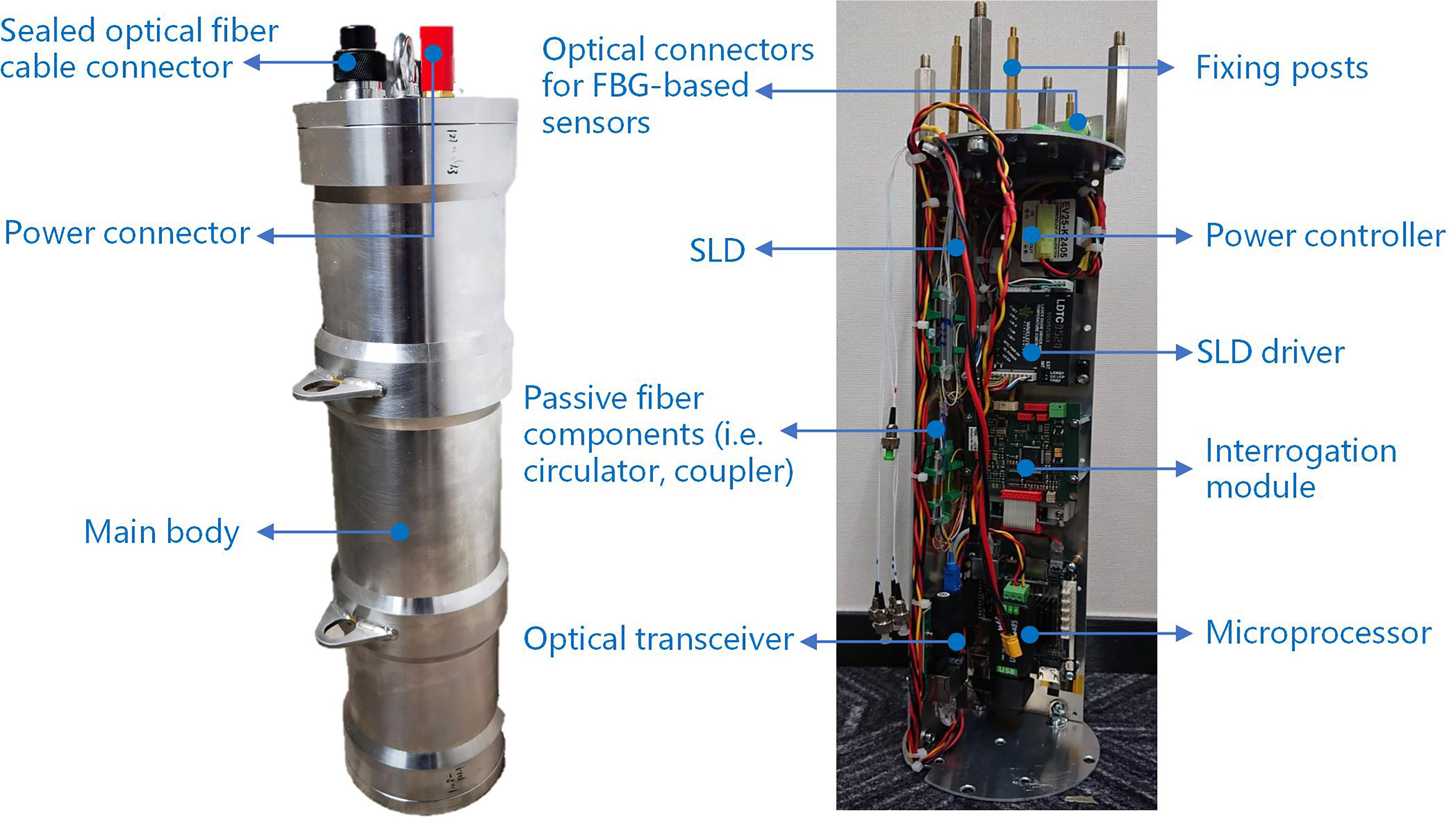
Figure 3 Captured image of the prototype of the developed submarine interrogation system.
Proof Test Under the Sea
To verify the feasibility and performance of the proposed submarine optical fiber sensing system, a proof test under the sea was carried out, as illustrated in Figure 4. Figure 4A shows the test route employed to create three different conditions in terms of depth, acceleration, and temperature, i.e., (D1, A1, T1), (D2, A2, T2), and (D3, A3, T3). The test was carried out in a specific area close to Pearl River Estuary in China, as shown in Figure 4B. Figures 4C, D are the photos captured during the sea test, and the submarine optical fiber sensing system is powered by an external battery. There is a commercial Conductivity, Temperature, Depth (CTD) device installed close to the system to provide a comparison to the monitored results.
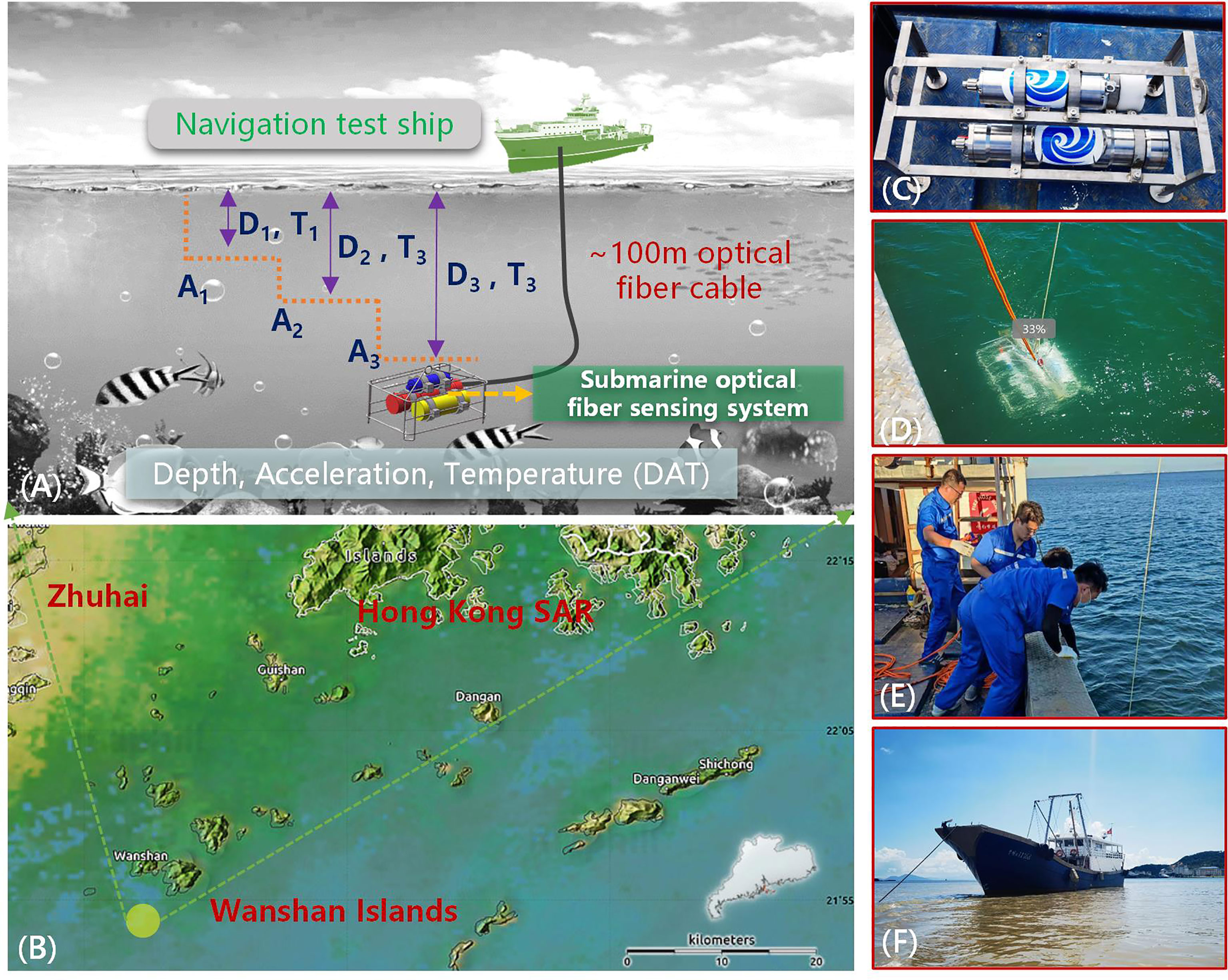
Figure 4 Illustration of the sea test conducted to verify the submarine optical fiber sensing system in a specific area close to Pearl River Estuary in China, where panel (A) is the test route employed to introduce three different conditions in terms of depth, acceleration, and temperature, panel (B) shows the test area near Wanshan Islands, and panels (C–F) are the photos captured during the field test.
Results
Calibration Results of the Optical Fiber Sensors
To test the proposed submarine optical fiber sensing system, highly sensitive pressure, temperature, and vibration sensors are developed based on the sensing principle of FBG described in Principle and Development of the Optical Fiber Sensors. The pressure sensor is utilized to monitor the depth determined by the relationship of h = P/pg, where P is the water pressure measured by the sensor, p is the mass density of the sea water, typically in the range of 1.02~1.07 g/cm3, and g is the gravitational acceleration equal to 9.8 m/s2. The pressure sensor is designed in a cylindrical tube of stainless steel, and the FBG with a Bragg wavelength of ~1,540 nm is packaged inside. As schematically illustrated in Figure 5A, the FBG is aligned in the center of the cylindrical tube and prestressed at one end. Once the water pressure is exerted on the top, the prestressed FBG gets released to some extent according to the value of pressure, resulting in a blue shift of the Bragg wavelength. The performance of the pressure sensitivity was characterized by placing the sensor in a hydraulic pressure chamber and increasing the pressure from 0 kPa to 0.5 MPa. For each state of the pressure, the Bragg wavelength was recorded. Figure 5A plots the response of the pressure sensor in terms of Bragg wavelength with respect to the applied pressure. From the experimentally measured results, the pressure sensitivity is -1.993 nm/MPa. The maximum calibrated pressure is up to 0.5 MPa, meaning that the depth variation could reach ~50 m.
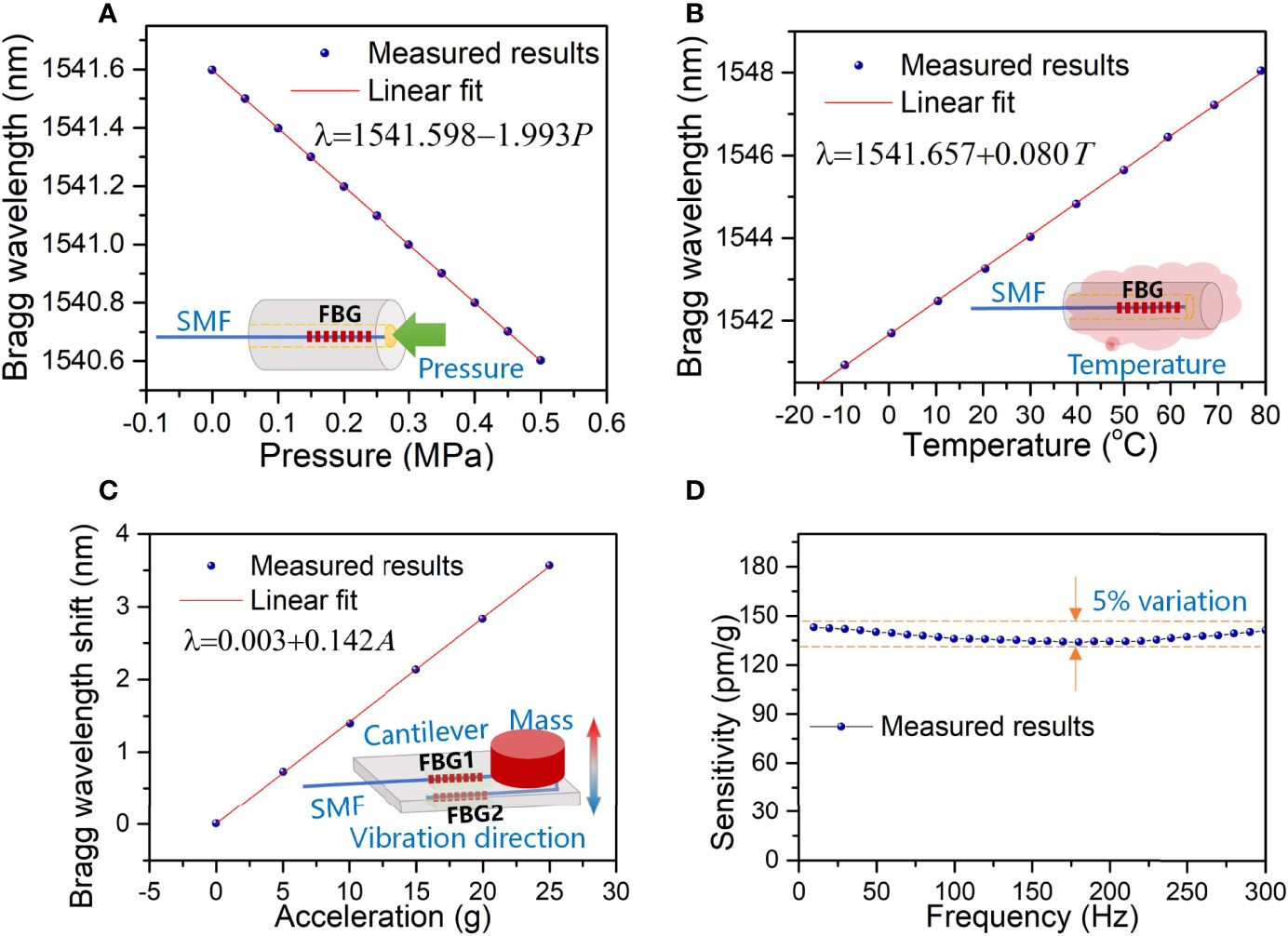
Figure 5 Experimentally measured responses of the pressure, temperature, and vibration sensors, where (A) and (B) are the Bragg wavelength as a function of pressure and temperature change, C shows the wavelength shift with respect to the applied acceleration of the vibration, and (D) plots the frequency response of the vibration sensor.
Similarly, the temperature sensor was characterized by placing it in an environment with the temperature controlled precisely. The sensing FBG is packaged and glued inside a cylindrical tube of stainless steel. By proper alignment, the FBG is absence of external strain during measurement, so that only the temperature induces a corresponding wavelength shift. As shown in Figure 5B, the calibrated temperature sensitivity is 0.08 nm/°C. Given that the resolution of the interrogation module is ~0.5 pm, the measurement resolution of the pressure and temperature can be ~0.25 kPa (corresponding to a depth variation of ~0.024 m) and 0.006°C, respectively. The relationship between the Bragg wavelength change and the measurands shows a good linearity, and the fitting R2 exceeds 0.999.
Regarding the vibration sensor, its sensing performance was investigated by applying various accelerations to the sensor in a fixed vibration direction. As schematically illustrated in the inset of Figure 5C, two FBGs are adhered on the top and bottom of the cantilever, which experience compression and tension strain, respectively, under a certain degree of vibration. The difference in the Bragg wavelengths of these two FBGs is utilized to characterize and calibrate the acceleration. After packaging the FBGs, the sensor was placed on a vibration shaker to induce the desired acceleration to the sensor. The actual acceleration was calibrated by an electric-based accelerometer. The shift between these two Bragg wavelengths vs. acceleration is plotted in Figure 5C, where the sensitivity is calculated to be 0.142 nm/g (g = 9.8 m/s2) and measured acceleration is up to 25 g. The FBG of the vibration sensor is packaged on a cantilever with an inertial mass at the top to induce periodical strain to the grating together with the vibration. The vibration at various frequencies was measured and the corresponding sensitivity was characterized, which is shown in Figure 5D. It can be observed that the response could remain nearly constant (within 5% variation) in a wide frequency range, and the sensor shows the sensing capability in small frequencies less than 10 Hz.
Real-Time Monitoring Results of the Depth, Acceleration and Temperature During the Sea Test
The proposed submarine optical fiber sensing system integrated with the pressure, vibration, and temperature sensors was tested and verified under the sea, as demonstrated in Figure 4. The entire system was laid down to three depths, i.e., ~5, ~10, and ~15 m under the sea level. The actual depth was also measured by the commercial CTD device. At each stage, the system was hanged on for over 1 h and then moved to the next level. The monitored results are shown in Figure 6, where the depth and temperature measured by the commercial CTD are plotted as well for comparison. From the results, it can be observed that the FBG-based sensors are able to measure the depth and temperature accurately, and small variations compared to the commercial CTD device are found. As for the acceleration, the sudden spikes clearly indicate the movement of the system to the next stage. Since there is no electrical vibration sensor installed on the commercial CTD device, no comparison is given. However, the moving posture of the sensing system is possible to be retrieved by the two acceleration sensors placed orthogonally, which managed to capture the slight vibration caused by the movement of the positioning or the undersea water. In this particular test lasting for a time duration of ~5 h, the first depth (~5.4 m) was reached at 13:43 on the testing day, and the monitored temperature by the FBG sensor dropped to 28.9°C. At this depth level, the temperature showed some minor fluctuations due to the non-uniform temperature distribution of the water. At 14:41, the second depth (~10.8 m) was reached and the temperature further dropped to ~23.8°C. As the depth was increased to ~15.5 m, occurring at 16:03, the reduction of the temperature was small, staying at about 23.2°C. The temperature distribution decreasing with the depth is similar to the general surface layer of the sea as reported previously (Duraibabu et al., 2017).
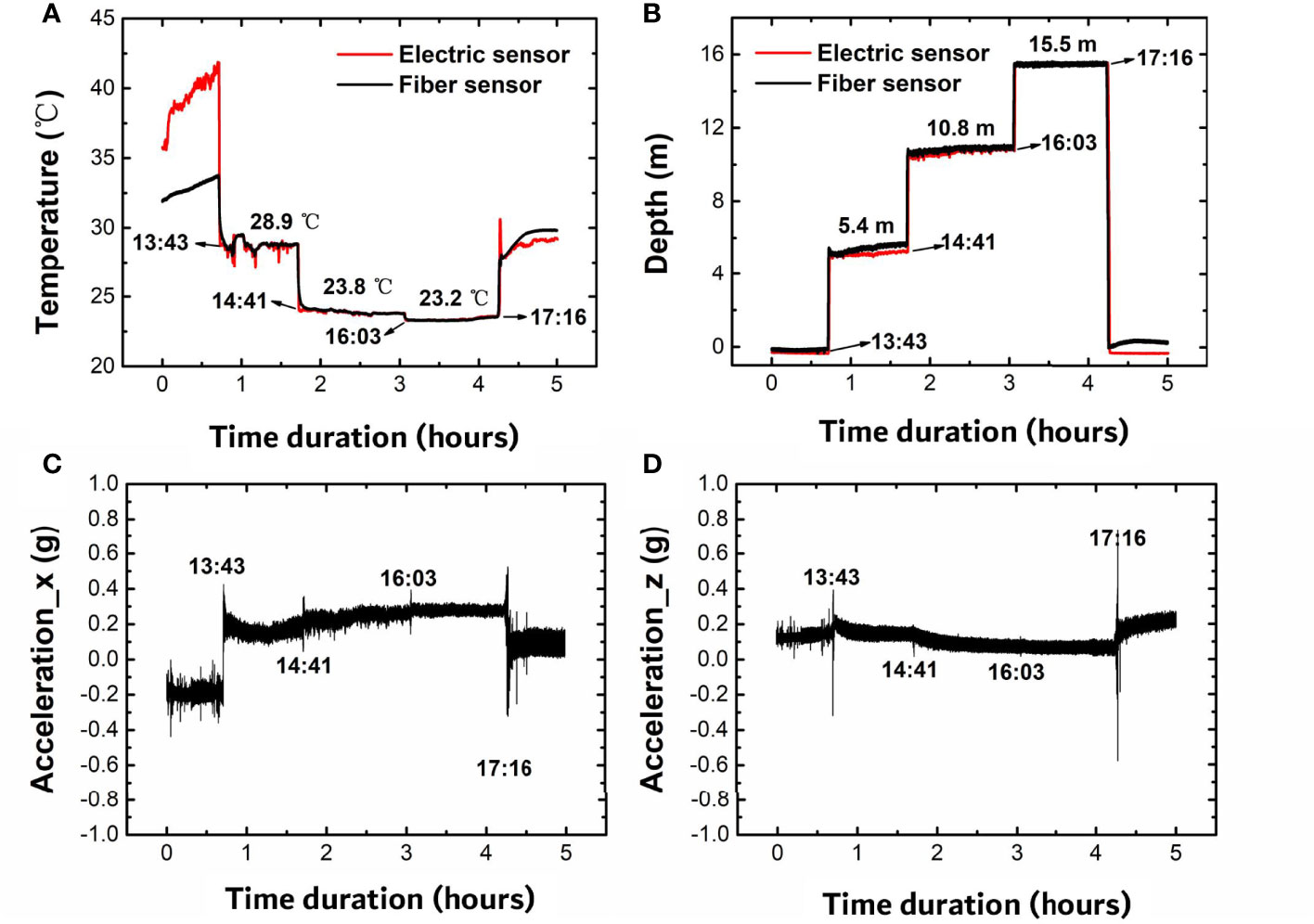
Figure 6 Measured results of the (A) temperature, (B) depth, and (C, D) acceleration by the submarine optical fiber sensing system under the sea.
Dynamics of the Surface Water Wave
During the sea test, the submarine optical fiber sensing system was also maintained at a certain depth (~15.4 m) for over 12 h to test the long stability and to retrieve the dynamics of the surface water wave according to the monitored pressure. Figure 7 plots the monitored depth, temperature, and acceleration in a time duration over 12 h, starting at 18:09 of the testing day and ending at 05:50 the next day. The test was conducted overnight, during which the temperature basically decreases gradually with time. This is confirmed from the measured temperature as illustrated in Figure 7C, which shows the sea water temperature at the depth of ~15.4 m under the sea drops from ~25°C to the lowest point of ~22.8°C. The measured acceleration during this time duration keeps still, since the entire system was maintained at the same depth, except the starting and ending moments, where the vibration was caused during the movement of sinking and taking out. By taking a closer view of the depth change with time shown in the inset of Figure 7A, a periodic depth change can be observed clearly, which is supposed to be the result of the surface water wave. The fast Fourier transform of the depth change over time is plotted in Figure 7B, showing a prominent peak at the frequency of ~0.25 Hz with a signal-to-noise ratio of >20 dB. This frequency component falls into the range of ocean surface waves observed by the GPS-tracked buoys (Herbers et al., 2012). Thus, it is possible to employ the proposed submarine optical fiber sensing system to realize the real-time investigation of the surface water wave.
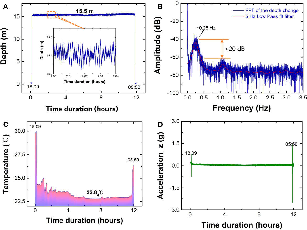
Figure 7 Measured results of the depth, temperature, and acceleration in a time duration over 12 h under the sea. (A, C, and D) are the depth, temperature, and acceleration monitored in real time, and (B) is the fast Fourier transform of the depth change in the time domain.
Discussion
To realize environmental monitoring in real time, various techniques have been developed and employed, including the seabed cabled observatories and distributed optical fiber sensing systems. Those systems are typically established in a large-scale area, and high cost is required. In those monitoring systems, the multiparameter sensors with high performance are in high demand. As demonstrated in this work, a submarine optical fiber sensing interrogation system is proposed and various optical fiber sensors could be integrated with the system. Since the optical fiber sensors are pluggable, the proposed system is flexible to conduct different measurements of multiple parameters. This feature allows it to monitor the sophisticated undersea environment with the ease of replacing the desired sensors.
To further investigate the repeatability of the sensor performance, new batches of the pressure, temperature, and acceleration sensors were fabricated in a similar approach as the sensors presented above have been installed in the system and being under monitoring of the field test. The sensing responses were measured three times, as displayed in Figure 8, where the error bar presents the standard deviation of the repeatable measurements. The averaged wavelength deviation of the pressure, temperature, and acceleration measurement is ~0.004, ~0.01, and ~0.02 nm, respectively, corresponding to a measurement accuracy of ~2 kPa, ~0.1°C, and ~0.14 g. It is worth noting that the measurement accuracy could be enhanced further by establishing more precise calibration and demodulating the FBG spectra using deep learning method (Cao et al., 2022), which we are currently working on.
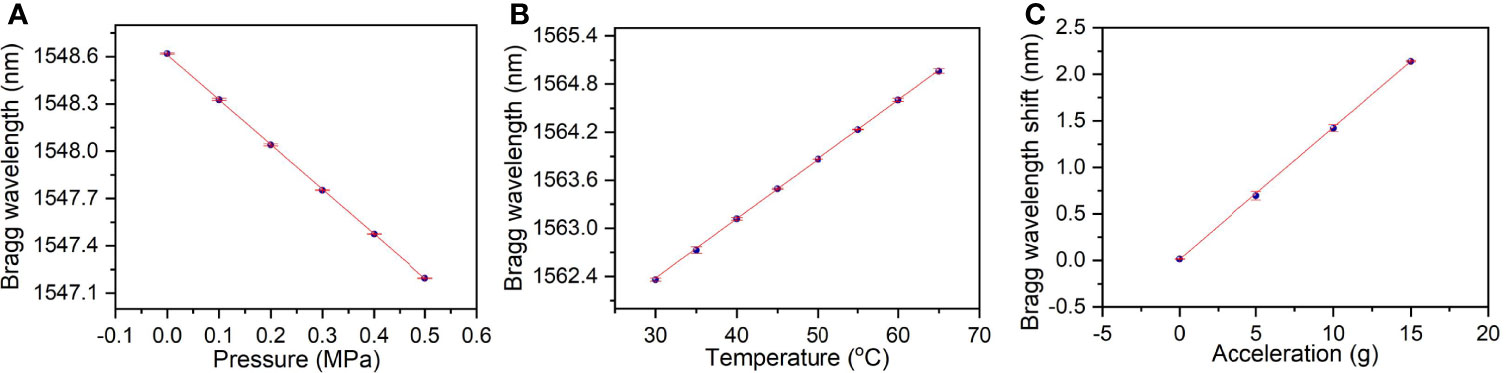
Figure 8 Measured responses of the (A) pressure, (B) temperature, and (C) acceleration sensors fabricated in the same way, where the error bar represents the standard deviation of the repeatable measurements.
As a proof test under the sea, preliminary results show good verification of the sensor system, and the pressure sensor is able to depict the curve of the depth during sinking while the temperature is monitored precisely at various positions. With regard to the vibration, a highly sensitive accelerometer is capable of recording the abrupt perturbation during the test. It is worth indicating that the resolution and limit of detection (LOD) of the sensors are not the best optimized during the verification test. Proper improvement in terms of the sensor structure, especially the novel packages with enhanced sensitivity, could be further investigated. With this regard, the simultaneous measurement of temperature, depth, and salinity is possible using a single optical fiber sensor. Prior examples can be found by the interferometric configurations, such as the FBG integrated with Fabry–Pérot interferometer (Liu et al., 2021), Fabry–Pérot interferometer with inline microcavity (Flores et al., 2019), Mach–Zehnder interferometer with core diameter mismatch structure (Selokar and Giraldi, 2021), Fabry–Pérot interferometer with U-shaped defect (Zhao et al., 2022b), and no-core fiber structure (Zhao et al., 2022a). All of these sensing structures show good sensitivity and discrimination of the multiple parameters based on a single structure. However, to realize the in situ monitoring under the sea, the stability and accuracy of the sensors need further investigation together with the submarine sensing system, as demonstrated in this work. With the integration of the interferometry-based fiber sensors, better algorithms such as deep learning method could be employed in the microprocessor of the proposed submarine interrogation system illustrated in Figure 2, which eventually retrieves the sensing signal in a smart approach. In a recent study (Cao et al., 2022), we have demonstrated that the spectrum of the FBG-based sensors can be directly demodulated by the deep convolutional neural network (DCNN) model, and good accuracy can be maintained; even the resolution of the hardware is reduced. This approach allows for the development of a compact and low-cost submarine sensing system, which is under investigation.
Conclusion
In conclusion, to achieve real-time monitoring of the environmental parameters under the sea, a submarine optical fiber sensing system is proposed. The principle of FBG-based sensors and the sensing system have been described. Basically, the proposed interrogation system is feasible to various sensors. As a demonstration of the sensing capability, the FBG-based pressure, acceleration, and temperature sensors are designed and utilized, respectively, for the measurement of the depth, vibration, and temperature. In the experiment, the achieved sensitivities of the pressure, temperature, and vibration sensors are -1.993 nm/MPa, 0.08 nm/°C, and 0.139 nm/g (g = 9.8 m/s2), meaning that the respective resolution can reach ~0.25 kPa, ~0.006°C, and ~0.004 g if taking the interrogation resolution of ~0.5 pm into account. A prototype of the submarine sensing system integrated with the FBG-based sensors was designed and manufactured. The proof test under the sea based on the prototype shows good capability of real-time monitoring of multiple parameters under the sea. The measured results during the sea test are comparable to the commercial CTD device installed at the same position, which exhibits the feasibility and accuracy of the proposed submarine sensing system. From the results of the sea test, the monitored depth change demonstrated a dominant frequency of ~0.25 Hz close to that of the surface water wave, which is promising for the long-term investigation of the dynamics of the ocean surface wave. The submarine optical fiber sensing system is able to integrate with various fiber sensors, and novel demodulation algorithms could be employed to realize the simultaneous measurement of multiple parameters with higher accuracy.
Data Availability Statement
The raw data supporting the conclusions of this article will be made available by the authors without undue reservation.
Author Contributions
ZYL conceived the idea of the work and wrote the article. SZ and CY conducted the experimental tests. ZYL and W-HC designed and manufactured the hardware of the optical fiber sensing system. ZYL and ZHL organized the sea test and supervised the project. All of the authors discussed the results and revised the article.
Funding
The authors would like to acknowledge the financial support from the National Natural Science Foundation of China under Grant Nos. 61905096, 61975250, and U2001601, also from the Science and Technology Planning Project of Guangzhou (202102020868), the Program of Marine Economy Development Special Fund (Six Marine Industries) under the Department of Natural Resources of Guangdong Province (Project No. GDNRC [2021]33), and the Innovation Group Project of Southern Marine Science and Engineering Guangdong Laboratory (Zhuhai) (No. 311021011).
Conflict of Interest
The authors declare that the research was conducted in the absence of any commercial or financial relationships that could be construed as a potential conflict of interest.
Publisher’s Note
All claims expressed in this article are solely those of the authors and do not necessarily represent those of their affiliated organizations, or those of the publisher, the editors and the reviewers. Any product that may be evaluated in this article, or claim that may be made by its manufacturer, is not guaranteed or endorsed by the publisher.
Acknowledgments
The authors would like to acknowledge Prof. Bo Liu from Nankai University and Prof. Xinwei Wang from the Institute of Semiconductors, Chinese Academy of Sciences, for the assistance during the sea test.
References
Ajo-Franklin J. B., Dou S., Lindsey N. J., Monga I., Tracy C., Robertson M., et al. (2019). Distributed Acoustic Sensing Using Dark Fiber for Near-Surface Characterization and Broadband Seismic Event Detection. Sci. Rep. 9, 1–14. doi: 10.1038/s41598-018-36675-8
Cao Z., Zhang S., Xia T., Liu Z., Li Z. (2022). Spectral Demodulation of Fiber Bragg Grating Sensor Based on Deep Convolutional Neural Networks. J. Light. Technol. 40, 1–1. doi: 10.1109/JLT.2022.3155253
Cheng W., Wang L., Hsieh C. (2003). Phase Masks Fabricated by Interferometric Lithography for Working in 248 Nm Wavelength. Microelectron. Eng. 67–68, 63–69. doi: 10.1016/S0167-9317(03)00060-1
Duraibabu D. B., Leen G., Toal D., Newe T., Lewis E., Dooly G. (2017). Underwater Depth and Temperature Sensing Based on Fiber Optic Technology for Marine and Fresh Water Applications. Sens. (Switzerland). 17, 7–10. doi: 10.3390/s17061228
Favali P., Beranzoli L. (2006). Seafloor Observatory Science: A Review. Ann. Geophys. 49, 515–567. doi: 10.4401/ag-3125
Flores R., Janeiro R., Viegas J. (2019). Optical Fibre Fabry-Pérot Interferometer Based on Inline Microcavities for Salinity and Temperature Sensing. Sci. Rep. 9, 9556. doi: 10.1038/s41598-019-45909-2
Gartman A., Findlay A. J. (2020). Impacts of Hydrothermal Plume Processes on Oceanic Metal Cycles and Transport. Nat. Geosci. 13, 396–402. doi: 10.1038/s41561-020-0579-0
Herbers T. H. C., Jessen P. F., Janssen T. T., Colbert D. B., MacMahan J. H. (2012). Observing Ocean Surface Waves With GPS-Tracked Buoys. J. Atmos. Ocean. Technol. 29, 944–959. doi: 10.1175/JTECH-D-11-00128.1
Hill K. O., Meltz G. (1997). Fiber Bragg Grating Technology Fundamentals and Overview. J. Light. Technol. 15, 1263–1276. doi: 10.1109/50.618320
Howe B. M., Angove M., Aucan J., Barnes C. R., Barros J. S., Bayliff N., et al. (2022). SMART Subsea Cables for Observing the Earth and Ocean, Mitigating Environmental Hazards, and Supporting the Blue Economy. Front. Earth Sci. 9. doi: 10.3389/feart.2021.775544
Howe B. M., Arbic B. K., Aucan J., Barnes C. R., Bayliff N., Becker N., et al. (2019). SMART Cables for Observing the Global Ocean: Science and Implementation. Front. Mar. Sci. 6. doi: 10.3389/fmars.2019.00424
Jousset P., Reinsch T., Ryberg T., Blanck H., Clarke A., Aghayev R., et al. (2018). Dynamic Strain Determination Using Fibre-Optic Cables Allows Imaging of Seismological and Structural Features. Nat. Commun. 9, 2509. doi: 10.1038/s41467-018-04860-y
Leal-Junior A. G., Díaz C. R., Marques C., Pontes M. J., Frizera A. (2019). Multiplexing Technique for Quasi-Distributed Sensors Arrays in Polymer Optical Fiber Intensity Variation-Based Sensors. Opt. Laser. Technol. 111, 81–88. doi: 10.1016/j.optlastec.2018.09.044
Leal-Junior A. G., Frizera A., Marques C., Sanchez M. R. A., dos Santos W. M., Siqueira A. A. G., et al. (2018). Polymer Optical Fiber for Angle and Torque Measurements of a Series Elastic Actuator’s Spring. J. Light. Technol. 36, 1698–1705. doi: 10.1109/JLT.2017.2789192
Leitão C., Leal-Junior A., Almeida A. R., Pereira S. O., Costa F. M., Pinto J. L., et al. (2021). Cortisol AuPd Plasmonic Unclad POF Biosensor. Biotechnol. Rep. 29, e00587. doi: 10.1016/j.btre.2021.e00587
Liu Z., Htein L., Lee K.-K., Lau K.-T., Tam H.-Y. (2018). Large Dynamic Range Pressure Sensor Based on Two Semicircle-Holes Microstructured Fiber. Sci. Rep. 8, 65. doi: 10.1038/s41598-017-18245-6
Liu Y., Jing Z., Liu Q., Li A., Lee A., Cheung Y., et al. (2021). All-Silica Fiber-Optic Temperature-Depth-Salinity Sensor Based on Cascaded EFPIs and FBG for Deep Sea Exploration. Opt. Exp. 29, 23953–23966. doi: 10.1364/OE.432943
Liu S.-Y., Tam H.-Y., Lee K.-K., Cheng K.-C. (2017). Optical Fibre Networks Facilitate Shift to Predictive Maintenance. Int. Railw. J. 57, 38–41.
Marques C. A. F., Bilro L. B., Alberto N. J., Webb D. J., Nogueira R. N. (2013). Narrow Bandwidth Bragg Gratings Imprinted in Polymer Optical Fibers for Different Spectral Windows. Opt. Commun. 307, 57–61. doi: 10.1016/j.optcom.2013.05.059
Marques C. A. F., Min R., Junior A. L., Antunes P., Fasano A., Woyessa G., et al. (2018). Fast and Stable Gratings Inscription in POFs Made of Different Materials With Pulsed 248 Nm KrF Laser. Opt. Exp. 26, 2013–2022. doi: 10.1364/oe.26.002013
Marra G., Clivati C., Luckett R., Tampellini A., Kronjäger J., Wright L., et al. (2018). Ultrastable Laser Interferometry for Earthquake Detection With Terrestrial and Submarine Cables. Science (80-. ). 361, 486–490. doi: 10.1126/science.aat4458
Min R., Liu Z., Pereira L., Yang C., Sui Q., Marques C. (2021). Optical Fiber Sensing for Marine Environment and Marine Structural Health Monitoring: A Review. Opt. Laser. Technol. 140, 107082. doi: 10.1016/j.optlastec.2021.107082
Najafzadeh A., Serandi Gunawardena D., Liu Z., Tran T., Tam H., Fu J., et al. (2020). Application of Fibre Bragg Grating Sensors in Strain Monitoring and Fracture Recovery of Human Femur Bone. Bioengineering 7, 98. doi: 10.3390/bioengineering7030098
Pospori A., Marques C. A. F., Bang O., Webb D. J., André P. (2017). Polymer Optical Fiber Bragg Grating Inscription With a Single UV Laser Pulse. Opt. Exp. 25, 9028–9038. doi: 10.1364/OE.25.009028
Qiao X., Shao Z., Bao W., Rong Q. (2017). Fiber Bragg Grating Sensors for the Oil Industry. Sensors 17, 429. doi: 10.3390/s17030429
Selokar T., Giraldi M. T. R. (2021). All-Fiber Sensors for Salinity and Temperature Simultaneous Measurement. Opt. Quant. Electron. 53, 1–17. doi: 10.1007/s11082-020-02678-x
Walter F., Gräff D., Lindner F., Paitz P., Köpfli M., Chmiel M., et al. (2020). Distributed Acoustic Sensing of Microseismic Sources and Wave Propagation in Glaciated Terrain. Nat. Commun. 11, 1–10. doi: 10.1038/s41467-020-15824-6
Wang L., Wang Y., Wang J., Li F. (2020). A High Spatial Resolution FBG Sensor Array for Measuring Ocean Temperature and Depth. Photo. Sens. 10, 57–66. doi: 10.1007/s13320-019-0550-0
Williams E. F., Fernández-Ruiz M. R., Magalhaes R., Vanthillo R., Zhan Z., González-Herráez M., et al. (2019). Distributed Sensing of Microseisms and Teleseisms With Submarine Dark Fibers. Nat. Commun. 10, 5778. doi: 10.1038/s41467-019-13262-7
Wu P., Tan D., Chen W., Malik N., Yin J. (2021). Novel Fiber Bragg Grating-Based Strain Gauges for Monitoring Dynamic Responses of Celtis Sinensis Under Typhoon Conditions. Measurement 172, 108966. doi: 10.1016/j.measurement.2021.108966
Xu M., Reekie L., Chow Y., Dakin J. P. (1993). Optical in-Fibre Grating High Pressure Sensor. Electron. Lett. 29, 398–399. doi: 10.1049/el:19930267
Yu K. (2015). Tsunami-Wave Parameter Estimation Using GNSS-Based Sea Surface Height Measurement. IEEE Trans. Geosci. Remote Sens. 53, 2603–2611. doi: 10.1109/TGRS.2014.2362113
Zhan Z., Cantono M., Kamalov V., Mecozzi A., Müller R., Yin S., et al. (2021). Optical Polarization–Based Seismic and Water Wave Sensing on Transoceanic Cables. Science (80-. ) 371, 931–936. doi: 10.1126/science.abe6648
Zhao Y., Wu Q., Zhang Y. (2019). Simultaneous Measurement of Salinity, Temperature and Pressure in Seawater Using Optical Fiber SPR Sensor. Measurement 148, 106792. doi: 10.1016/j.measurement.2019.07.020
Zhao J., Zhao Y., Cai L. (2022a). Hybrid Fiber-Optic Sensor for Seawater Temperature and Salinity Simultaneous Measurements. J. Light. Technol. 40, 880–886. doi: 10.1109/JLT.2021.3121674
Keywords: optical fiber sensing, fiber bragg grating, submarine real-time monitoring, environmental monitoring, optical fiber sensor
Citation: Liu Z, Zhang S, Yang C, Chung W-H and Li Z (2022) Submarine Optical Fiber Sensing System for the Real-Time Monitoring of Depth, Vibration, and Temperature. Front. Mar. Sci. 9:922669. doi: 10.3389/fmars.2022.922669
Received: 18 April 2022; Accepted: 25 May 2022;
Published: 24 June 2022.
Edited by:
Surui Xie, University of California, San Diego, United StatesCopyright © 2022 Liu, Zhang, Yang, Chung and Li. This is an open-access article distributed under the terms of the Creative Commons Attribution License (CC BY). The use, distribution or reproduction in other forums is permitted, provided the original author(s) and the copyright owner(s) are credited and that the original publication in this journal is cited, in accordance with accepted academic practice. No use, distribution or reproduction is permitted which does not comply with these terms.
*Correspondence: Zhengyong Liu, bGl1emhlbmd5QG1haWwuc3lzdS5lZHUuY24=