 Hao Wang
 Jiawang Chen
 Qixiao Zhou
 Xiaohui Hu
 Qiaoling Gao
 Jin Guo
- Ocean College, Zhejiang University, Zhoushan, China
The study of deep-sea fauna is one of the essential themes of marine scientific research. For all that, the biology of deep animals remains largely unknown, such as their behaviors, metabolic characteristics, and mechanisms of adaptation to the deep-sea environment. Obtaining samples in good condition is an essential prerequisite for these investigations. The isobaric samplers were created to keep the organisms as much as possible in the in-situ environment during recovery. This report reviews the history and the application of isobaric samplers for deep-sea animals established by researchers worldwide over the past hundred years. Also, the crucial technologies of isobaric samplers are analyzed and summarized, including pressure compensation, insulation, sealing, etc. Finally, prospects for the future development of isobaric sampling technologies from the aspects of high fidelity, function integration, and real-time communication and integration operation. This review can provide a reference for future design and optimization of fidelity samplers for deep-sea animals.
1 Introduction
The deep-sea habitats are characterized by low temperature, high pressure, darkness, and oligotrophy. Despite the harsh environment, the deep sea is still the most biodiverse region on earth (Thurber et al., 2014; Gooday et al., 2020). The systematic study of biological resources and biodiversity of deep-sea ecosystems is of great scientific importance for mankind to reveal the origin of life and the unique environmental adaptation mechanisms of deep-sea organisms (Sandulli et al., 2021). The investigation of deep-sea habitats began in the late 19th century. In the last hundred years, the development of deep-sea exploration techniques and many exciting discoveries have stimulated worldwide interest in the deep-sea ecosystem (Ramirez-Llodra et al., 2010). Up to the present, our understanding of deep-sea ecosystems is still very limited compared to the complex studies conducted on shallow-sea ecosystems (Jamieson, 2018), which is mainly due to the deficiencies in observation and sampling techniques (Jamieson et al., 2009).
There are currently two methods for conducting experiments on deep-sea bio physiology, i. e., laboratory and in-situ methods. Laboratory research entails capturing, recovering and maintaining the macro-organisms. The in-situ method deploys scientific instruments to the seafloor to directly observe organisms and measure some physiological parameters. The fact is that both methods have unavoidable limitations, and we cannot claim that either method is superior. Limitations of the laboratory method include the apparent effects in the process of capturing; increased temperature and reduced pressure during recovery (Garel et al., 2019); the influence of artificial light on the animals accustomed to dark environments; restriction of organisms to a container after capture, and the abnormal movement during recovery (e.g., stochastic swaying and vibration) etc. (Smith and Brown, 1983). The in-situ method has less impact on the creatures but still does not avoid the effects of the capture process and artificial light sources. The disadvantage of the in-situ method is that the availability and complexity of observations and experiments are severely restricted (Smith and Baldwin, 1997).
Nevertheless, both methods have a wide range of applications. In-situ methods such as baited cameras are deployed on a lander to reach the seafloor, where a camera records photos or videos of the activity of organisms attracted by the baits (e.g., Cappo et al., 2006; Phillips et al., 2019; Giddens et al., 2021; Jamieson et al., 2021). Towed cameras are mounted on the cables of research vessels to observe organisms at large geographic scales (e.g., Jones et al., 2009; Lembke et al., 2017; Purser et al., 2018). Seafloor Observatories (e.g., White et al., 2003; Favali and Beranzoli, 2009; Aguzzi et al., 2011; Aguzzi et al., 2015) can be deployed on the seafloor for an extended period for continuous observations. Their purpose is to provide scientists with valuable opportunities to study multiple interrelated processes on long-time scales and to conduct comparative studies of processes in different regions (Clark et al., 2016).
Here, we focus on the equipment used to capture and recover organisms. In the past, people have used tools including trawls (e.g. Fanelli et al., 2018; Bosley et al., 2020; De Mendonça and Metaxas, 2021), longlines (e.g. Crespo et al., 2018; Pinho et al., 2020; Prohaska et al., 2021), sledges (Lins and Brandt, 2020; Jóźwiak et al., 2020; Linse and Anderson, 2021), and grabs (e.g. Mortensen et al., 2000; Murton et al., 2012; Przeslawski et al., 2018) to collect animals from the deep sea. Unfortunately, these sampling methods usually cause mechanical damage to organisms and cannot recover organisms while keeping in-situ pressure and temperature. With the development of materials science and submersible technology, some innovative, flexible tools can be used to capture animals on the seafloor with the assistance of submersibles without any mechanical damage. However, these apparatuses still do not take adequate measures to maintain the ambient pressure and temperature during recovery (Teoh et al., 2018; Vogt et al., 2018). However, many animals in deep sea could be easily affected by depressurization, such as loss of muscle coordination, abnormal gene expression, destruction of some protein structures, and impairment of enzyme functions (Somero, 1992). The piezophilic megafauna tends to be irreversibly damaged (Fang et al., 2010). Chen et al. (2021) evaluated the response of isobaric and unpressurized samples of deep-sea mussels and their symbionts to depressurization stresses. The results show that depressurization leads to intense DNA fragmentation. This phenomenon was also observed in tubeworms recovered at atmosphere pressure (Dixon et al., 2002). Yan et al. (2022) confirmed the extensive transcriptomic variations in response to pressure during unpressurized sampling. These studies suggest the necessity of pressurized sampling in deep-sea biology studies. It is necessary to take specific measures to isolate the sample container’s environment from the external environment during recovery. Isobaric samplers are built for this purpose.
In this review, we first introduce the typical isobaric samplers established for deep-sea animals. Secondly, we analyze the critical technologies of isobaric sampling, including pressure compensation, sealing, insulation, etc. Finally, we summarize the difficulties of isobaric sampling technology and prospect its future development.
2 Development and application of isobaric sampler
The working procedure of deep-sea macro organisms’ samplers could be divided into the following four stages:
1. The sampler is deployed from the scientific research ship to the depths.
2. Capture organisms at depths.
3. Close the entrance of animals and seal the pressure vessel.
4. Ascent to the surface, retaining the in-situ pressure.
There are many ways to classify these samplers, for example, in terms of deployment methods, whether lowered by a cable on the ship, carried by a submersible, or deployed as a free-fall vehicle. The deployment methods determine the choices of energy supply, communication, control and recovery technologies, etc. From another perspective, how does a sampler capture animal? Is it by a pump, a hook, or baited trap? The capture method depends on the target species, which determines the structural design of the sampler. In this section, we introduce the typical isobaric samplers in the timeline of the establishment time.
Macdonald and Gilchrist (1969) proposed the first deep-sea animal pressure-retaining sampler (here, we call it the recovery apparatus) (Figure 1). The sampler was built to obtain plankton by filtration at different depths and recover them to the sea surface with constant pressure. The recovery apparatus was connected to the experiment apparatus, and plankton was transferred into the experiment vessel with low-pressure fluctuations. With the optical and polarographic components equipped on the experimental apparatus, the scientist are allowed to study the respiration, activity and survival of plankton. The weight of the recovery apparatus is 180kg, consisting of a stainless-steel pressure vessel (inner diameter, 5.08cm, length, 55.8cm), a global valve (diameter, 2.54cm), a hydraulic accumulator, a depth recorder and pressure transducer. The recovery apparatus is connected to the coring wire on the ship and deployed to the specified depth. The ball valve closed on the seabed by a messenger-actuated device triggering an extension spring coupled to the valve spindle. In November 1968, the prototype of the recovery apparatus was field tested at depths of 1400m and 2000m. The recovered pressures were equal to or greater than (possibly due to temperature rising) the pressure at the sampling depth in all four trials.
Figure 1 Schematic diagram of the recovery apparatus (1: Globe valve;2: recovery pressure vessel;3: frame;4: plug;5: depth recorder;6: hydraulic accumulator;7: pressure transducer housing) (adapted from Macdonald and Gilchrist, 1969).
Brown (1975) established a pressure fish trap to capture deep-sea fish. The pressure vessel of the sampler was made of polyethylene (inner diameter, 30cm, length, 2m) (Figure 2). A trap door that closed inside was used to seal the pressure vessel. The sampler is deployed to the seabed as a free vehicle, the upper plate is connected to a float on the sea surface, and the lower plate is connected to a disposable ballast. The trigger mechanism of the trap door is an elastic cord with a bait at the end. Once the cord is subjected to a pull of more than 1kg, a pull of 15kg is generated on the cord to pull the fish in, and the door closes. Due to limitations of the material, the pressure fish trap was equipped with a pressure-release valve with a set pressure of 6 atm (0.6 MPa). The sampler successfully obtained pressure-retained live fish samples at a depth of 1200m.
Figure 2 Photos of pressure fish trap. (A) Fish trap with grenadier or rattail about 60cm long caught in trap at depth of 1200m. (B) Pressure fish trap, internal door bottom, lower end plate. (C) Pressure fish trap, upper end plate with access port and air vent valve.) (adapted from Brown, 1975).
(Yayanos, 1977; Yayanos, 1978; Yayanos, 2009) reported a novel sampler PRAT (pressure-retaining amphipod trap) (Figure 3). The device weighs 21.8kg in air and 16.4kg in water. The system was also deployed as a free vehicle. The disposable ballast is connected to the bottom of a release device, and the top of the release device is connected to the sampling piston through an extension spring. The sampling piston keeps the passage open under the gravity of the ballast. A timer event triggers the release device. After the disposable ballast is released, the sampling piston blocks the passage and the O-rings at both ends of the piston seal the vessel. There are two windows for observation on the side wall. A piston gas accumulator and a “water jacket” insulation sleeve are used to reduce pressure and temperature changes. Different from traditional pressure vessels, the pressure retaining chamber of PRAT is a 24.1×24.1×8.26cm square vessel made of titanium alloy. In June 1977, PRAT was deployed four times at a depth of 5741 to 6049m, and the pressure retaining rate was between 66.3% to 95%. In November 1980, PRAT obtained a living sample of amphipods in the Mariana Trench at a depth of 10900m, with a recovery pressure of 102.6MPa, which was the first time in the world to obtain a living animal in the Mariana Trench.
Figure 3 Photos of PRAT (A) detailed structure of PRAT. 1: The cable connected to the floats;2: Window;3: The piston end;4: Insulating box;5: Springs;6: Accumulator;7: The rod connected to the ballast;8: The stop of piston;9: Valve for charging of nitrogen;10 and 11: Valves connected to high-pressure seawater circulating system; 12: the trap body; (B) field test of PRAT (adapted from Yayanos, 1978; Yayanos, 2009).
Macdonald and Gilchrist (1978) reported a novel sampler for amphipods (here we call it the High-pressure Trap) (Figure 4). The High-pressure Trap is a baited benthic trap, which was established to minimize the damage caused by trapping amphipods. The High-pressure Trap includes a globe valve (diameter 2.5cm), a pressure vessel made of stainless steel (diameter over 7.5cm), an enclosing water jacket, a conical plastic window and a hydraulic accumulator. Before a cast of the trap, the pressure vessel was pressurized to a pressure equal to that of operation depth, and then the spindle of the ball valve was connected to the extensible drawbar at the end of the cable. During a deployment to the seafloor, the globe valve is closed due to tension on the cable. After arriving at the seabed, the tension on the cable disappeared, and the globe valve was opened by an extension spring coupled to the spindle of the globe valve. In the same way, when recovering, the tensile force on the cable will close the globe valve again. During the Challenger cruise in 1976, High-pressure Trap was field tested three times at a depth of 1300m and obtained some tmetonym cicada. The pressure drop does not exceed 4.3% after recovery.
Figure 4 Schematic diagram and photo of High-pressure Trap (A): 1: Valve;2: Stop;3: Trigger;4,5: Thermal Insulation;6: Bait chamber;7: Sample chamber;8: Water jacket;9: Viewing window;10: End plate;11: Globe vlave;12: Globe valve body;13: Entrance (B) Photo of High-pressure Trap [adapted from Macdonald and Gilchrist, 1978; Macdonald, (2021)].
Phleger et al. (1979) built a hyperbaric fish trap to study the structure and function of biofilms of deep-sea fish when they are swimming (Figure 5). The pressure vessel of the sampler is made of aluminum alloy and contains a flap door for sealing. A piston accumulator was used to compensate for the pressure loss. A plexiglass window is installed on the end plate of the trapper, and a chemiluminescent element is installed inside it, so as to better observe the movement of animals in the trapper. The sampler includes a pressure relief valve with a set pressure of 2250 psi (15.5 MPa) for security. Hyperbaric fish trap reaches the seabed as a free vehicle. On the seafloor, fish were captured in two ways. One is to use a long rope to attract fish, and the hook is connected to a spring in the cabin. When the fish bites the hook, it will trigger a series of events, including the ballast releasing, the spring pulling the fish in, and the flap valve closing. The second is to coat the trapping mechanism near the entrance with chemiluminescent substances to attract fish. The hyperbaric fish trap successfully captured two fishes at 750 m and 1200 m.
Figure 5 Cross section of hyperbaric fish trap (1:Pressure gauges; 2:Window to view fish; 3:Plexiglass; 4:Negator spring(pulls fish in- and closes door after tugging fish releases ballast); 5:Main AI tube; 6:Line between negator spring and fish hook; 7:Line to pin; 8:Large AI tube; 9:Pin; 10:Shock cords to close door; 11:Loops; 12:Taut wire inserted in small hole in end plate; 13:Baited hook; 14:Handling bracket; 15:Spring; 16:Line to baited strings and ballast weights; 17:crimps; 18:Fish-triggered release)(adapted from Phleger et al., 1979) Wilson and Smith (1985) established a hyperbaric trap-aquarium (Figure 6). The device contains an aluminum pressure vessel (inner diameter, 22.9cm, outer diameter, 26.7cm) with an adequate volume of 41.7L.
Figure 6 Schematic diagram of hyperbaric trap-aquarium (1:Pressure gauges; 2:Window; 3:Plexiglass; 4:Negator spring(pulls fish in- and closes door after tugging fish releases ballast); 5:Main AI tube; 6:Line between negator spring and fish hook; 7:Line to pin; 8:Large AI tube; 9:Pin; 10:Shock cords to close door; 11:Loops; 12:Taut wire; 13:Baited hook; 14:Handling bracket; 15:Spring; 16:Line to baited strings and ballast weights; 17:crimps; 18:Fish-triggered release)(adapted from Phleger et al., 1979).
The accumulator system of the hyperbaric trap-aquarium includes a nitrogen cylinder, a pressure-reducing regulator and a piston accumulator. The nitrogen cylinder can deliver nitrogen gas to the piston accumulator according to the pressure setting of the pressure relief valve. The pressure vessel was covered with nine layers of pipe-wrapping tape to slow the temperature rise. Unlike other flap-closing mechanisms, the door of this system closes from the outside. Triggered closing action by Derlin burn-wire release, the spring closes the doors at the two ends for sealing. From September 1984 to January 1985, the device was deployed 49 times at depths of 1115m to 1241m, but with only 12 complete operations. The pressure retaining rate was between 13% to 95%.
(Koyama et al., 2002; Koyama, 2010) established a pressure-stat aquarium system for isobaric recovery and maintenance of deep-sea organisms (Figure 7). The sampler consists of a spherical pressure vessel made of stainless steel (outer diameter, 36cm, inner diameter, 34cm) with three round holes in the side wall for installing windows made of acrylic resin. The device weighs 52kg in air and 44kg in water, and the practical volume is 20L. The spherical vessel withstands a maximum internal pressure of 30MPa. A pressure control valve with a set pressure of 20MPa is installed for safety. A gas-filled bladder compensator is installed inside to reduce the pressure drop. The outside of the vessel is covered with an insulating layer. The device was deployed by the ROV to a specific depth and pumped the organisms into the pressure vessel through an inhalation apparatus mounted on the ROV. Then the manipulator of the ROV pulls out the limit pin of the sealing door installed in the chamber, and the compression spring pushes the doors to the inner wall to seal the vessel. In December 2001, the pressure-stat aquarium system captured a deep-sea fish at a depth of 1171m, and the pressure retaining rate was 84%.
Figure 7 Schematic diagram and photo of pressure-stat aquarium (A): Capture procedure of pressure-stat aquarium; (B): Pressure vessel was sealed by the sealing door; (C): Photo of pressure-stat aquarium (adapted from Koyama et al., 2002).
Drazen et al. (2005) established a hyperbaric trap respirometer for measuring the breath rate, pressure tolerance and metabolic of fish that respond to different environments (Figure 8). The device consists of a pressure vessel made of 17-4 PH stainless steel (inner diameter, 30.5cm, length, 122cm), thermal insulation (2 layers of 2.5cm thick high-strength foam), and a pre-charged piston accumulator. At the same time, a light-emitting diode, a circulation pump and a camera were installed in the chamber. This device has a total weight of approximately 680kg and is deployed as a free vehicle. The external hook is connected to a high-strength elastic cord coupled with a coil spring when working on the seabed. A fish bite will trigger a sequence of events. First, the coil spring rotates to release the limitation of the flap valve, and the spring slowly pulls the fish into the vessel and closes the flap valve. A hydraulic damper is used to prevent mechanical damage to organisms. The sampler was deployed 7 times at depths of 1430-1500 m, with pressure retaining rates between 93% and 95%.
Figure 8 Schematic diagram of hyperbaric trap respirometer (1: Pin to hold the release shackle/hook assembly; 2: Retraction line connected to hook; 3: Door; 4: Door linkage system; 5: Door latch; 6: Hydraulic dampening piston; 7: Line to door release plate; 8: Tubing to draw water to pump; 9: Extension springs; 10: Camera with integrated LED lighting; 11: Wheels for coiled constant force springs; 12: Oxygen probe; 13: Water circulation pump; 14: Release trigger for door.)(adapted from Drazen et al., 2005).
Shillito et al. (2008) proposed a sampler device PERISCOPE, which is mounted on a submersible (Figure 9). The manipulator on the submersible holds the sampling tube, which is connected to a suction instrument to capture animals. After organisms are sucked into the sampling tube, the submersible places the sampling tube into the pressurized recovery device (PRD). Different from the traditional gas accumulator, the PRD system adopts the high-pressure liquid pressure compensation technology, which can adjust the pressure in real time. In August 2006, PERISCOPE carried out 8 deployments in hydrothermal areas and successfully retained pressure 6 times. The maximum deployment depth in this voyage is 2290m, and the pressure retaining rate is 82%-111%. In 2012, the PERISCOPE sampler took four operations at 2500m and obtained 70 worms with a pressure retaining rate between 68% and 91% (Ravaux et al., 2013).
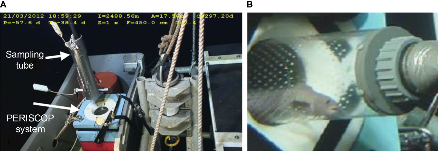
Figure 9 Photos of PERISCOPE (A, B): the sampling tube is placed into the pressure vessel of the PERISCOP (adapted from Shillito et al., 2008; Ravaux et al., 2013) Zaharina et al. (2020) proposed a large-scale deep-water trap whose working depth is 1000m.
The pressure vessel is made of 304 stainless steel (inner diameter, 500mm, length, 615mm). A drum in the pressure chamber is divided into three equal parts. Two chambers had no side walls and were used to place baits. Another chamber has a third cylindrical side wall for sealing. When it closes, the motor drives the drum to rotate, and the side wall of the drum presses the inner wall of the pressure vessel to form a self-tight seal. In addition, there are 4 cylinders with compression springs designed to reduce friction when rotating, providing an initial force to compress the sealing ring. (Wang et al., 2020; Wang et al., 2022) proposed a pressure-retaining trapping instrument (PMTI) that can be applied to the full-ocean depth (Figure 10). The sampler adopts a novel sampling structure, the hollow piston, which automatically forms a seal after sampling, avoiding the design of an additional closing device. This sampler weighs 61.4kg in water, including a pressure vessel made of titanium alloy TC4 (inner diameter, 80mm, outer diameter, 124mm), a piston pressure compensator, a transmission mechanism and an in-situ pressurization mechanism. The sampler adopts a semi-active pressure compensation method. After the sampling operation, pure water (about 4.7ml) in a small piston cylinder is injected into the pressure vessel to improve the pressure retaining rate. In August 2021, it was field tested in the China Ocean Scientific Expedition voyage TS-21 and performed four deployments, two of which successfully captured 174 amphipods, and the pressure retaining rate is between 82.7%-84.5%.
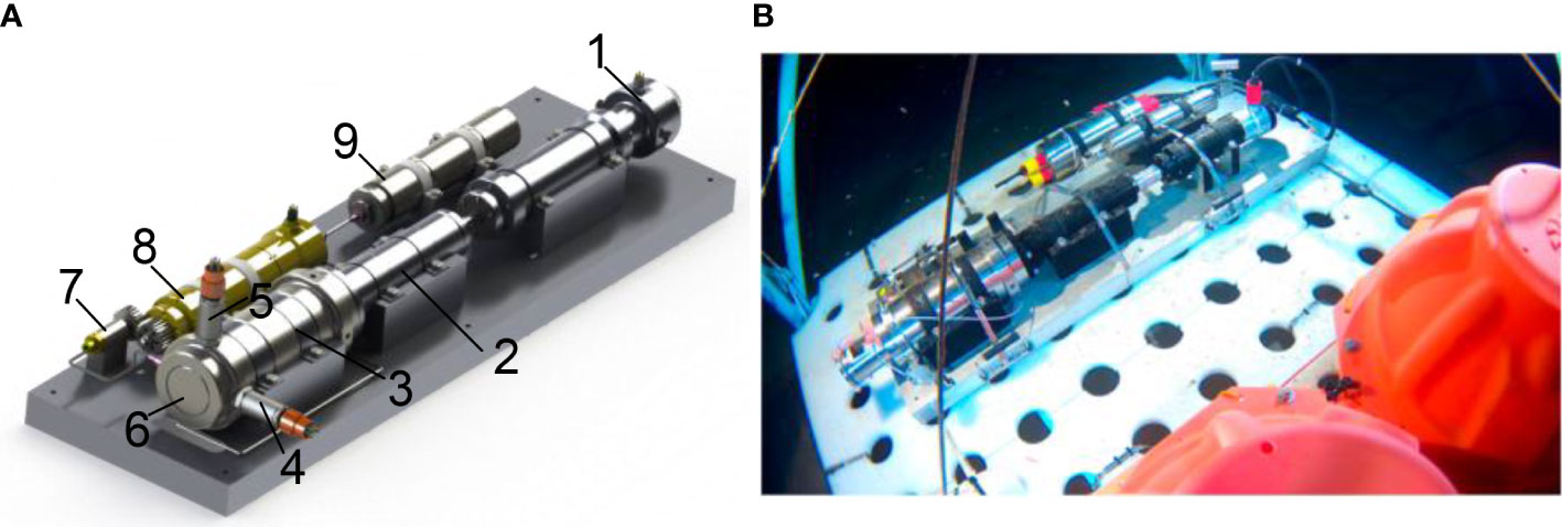
Figure 10 Schematic diagram and photo of PMTI (A): 3D model of PMTI (1: sampling motor; 2: screw mechanism; 3: pressure vessel; 4: temperature probe; 5: pressure probe; 6: sampling piston; 7: pressurizing cylinder; 8: pressurizing motor; 9: piston accumulator); (B): PMTI working at seabed) (adapted from Wang et al., 2022).
This section introduces almost all the typical isobaric samplers for macro organisms. For over one hundred years, people have kept enhancing the isobaric samplers, and we summarize their development trends as follows: (1) The application depth of isobaric samplers is getting deeper, and some of them can operate at full ocean depth. (2) The early pressure-retaining samplers could only collect samples. However, now the samplers are multifunctional, such as measuring some basic biochemical parameters and maintaining the life of organisms for experimental purposes. (3) The development of submersible technology allows us to complete refined sampling operations at specific locations. Compared with the operation of earlier samplers, submersible-equipped samplers tend to have a higher sampling success rate. At the same time, diverse technologies have been integrated and applied to deep-sea biological sampling, such as semi-active and active pressure compensation and insulation technologies, various sealing components, etc. We summarize the technologies applied in these samplers (Table 1) and expect them to be useful to designers.
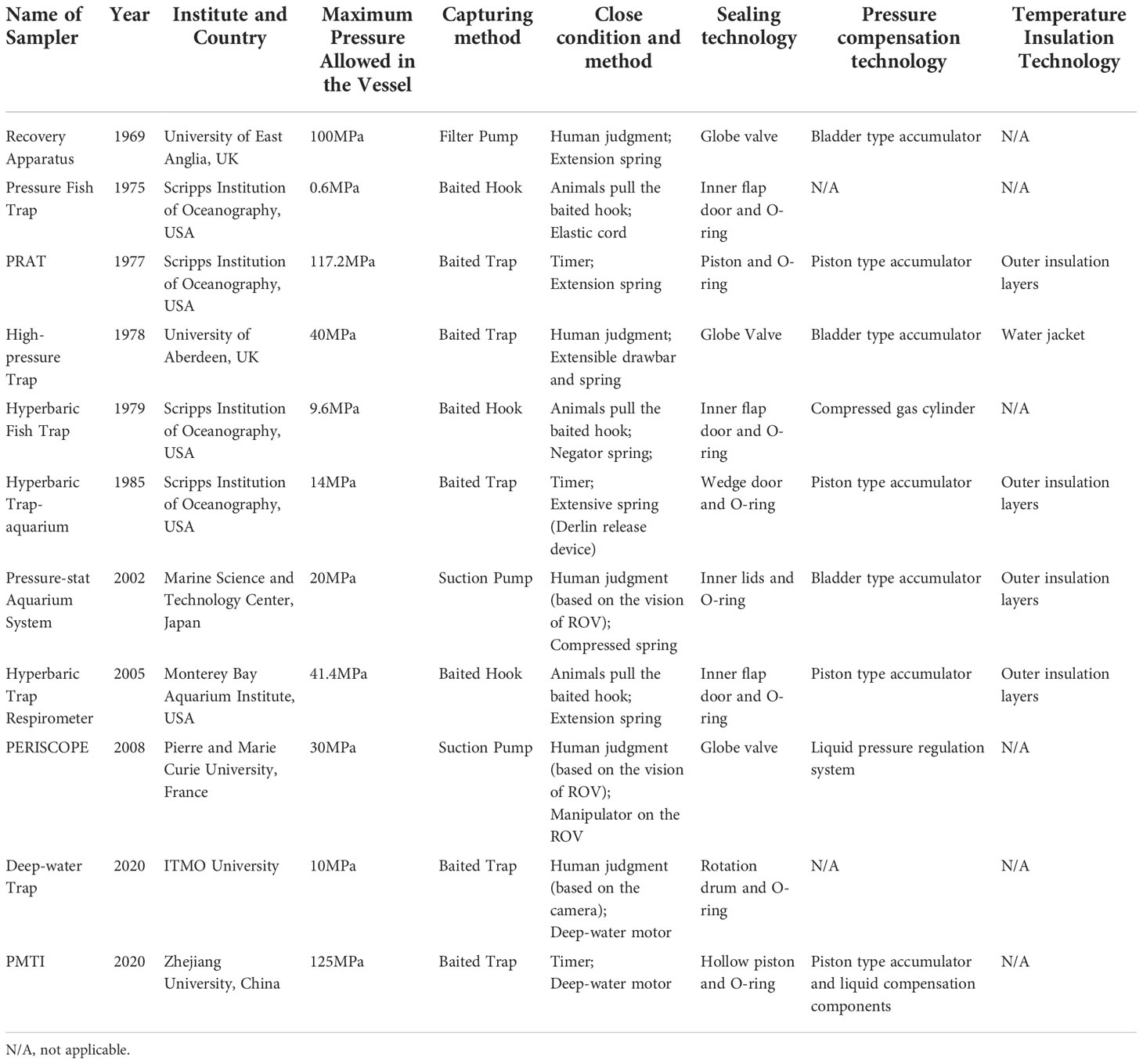
Table 1 Isobaric samplers and the key technologies.
3 Key techniques
3.1 Pressure compensation technology
The pressure in the vessel reduces during its ascent from the seabed to the surface due to many factors such as metal expansion, seal movement and leakage, etc. To improve the pressure retaining rate, we need to take a practical approach to reduce the pressure drop. Pressure compensation technologies can be divided into three types, passive, semi-active and active. Passive pressure compensation technology uses high-pressure gas to compensate for the pressure loss. Semi-active and active compensation technologies do not rely on pressurized gas entirely but some other methods to improve the pressure in the vessel. There are two ways to increase the pressure in a vessel. One is to compress the volume of the vessel (the volume of water does not change), another is to increase the volume of water in the vessel (the volume of the vessel does not change). Passive and semi-active pressure compensation techniques apply the first principle, and active compensation techniques apply the second.
3.1.1 Passive pressure compensation technology
Passive pressure compensation technology is widely used in the deep-sea pressure-retaining sampler. It is usually achieved by an accumulator filled with high-pressure gas (usually nitrogen). The main principle of this technology is to use the different compression ratios of gas and seawater. When the pressure in the sample chamber decreases, gas volume expansion will be much more significant than that of liquid since the volumetric compression ratio of gas is thousands of times that of liquid. In this way, it can compensate for pressure loss partially. Generally speaking, the pre-charge pressure of the accumulator should be lower than the pressure at the sampling location. Otherwise, the accumulator will lose its function. As a result, the gas accumulator is not sufficient to fully compensate for the pressure loss.
Accumulators can be divided into piston accumulators, diaphragm accumulators and bladder accumulators. Piston accumulator has the advantages of high flow rates, wide application temperature range and high-pressure tolerance (Hiis et al., 2019). The working principle of the latter two types of accumulators is similar and has the advantage of a short response time (usually no more than 25ms). Most of the samplers adopted the bladder accumulator and the piston accumulator. When the depth exceeds 3500m, piston accumulators are more commonly used (Figure 11).
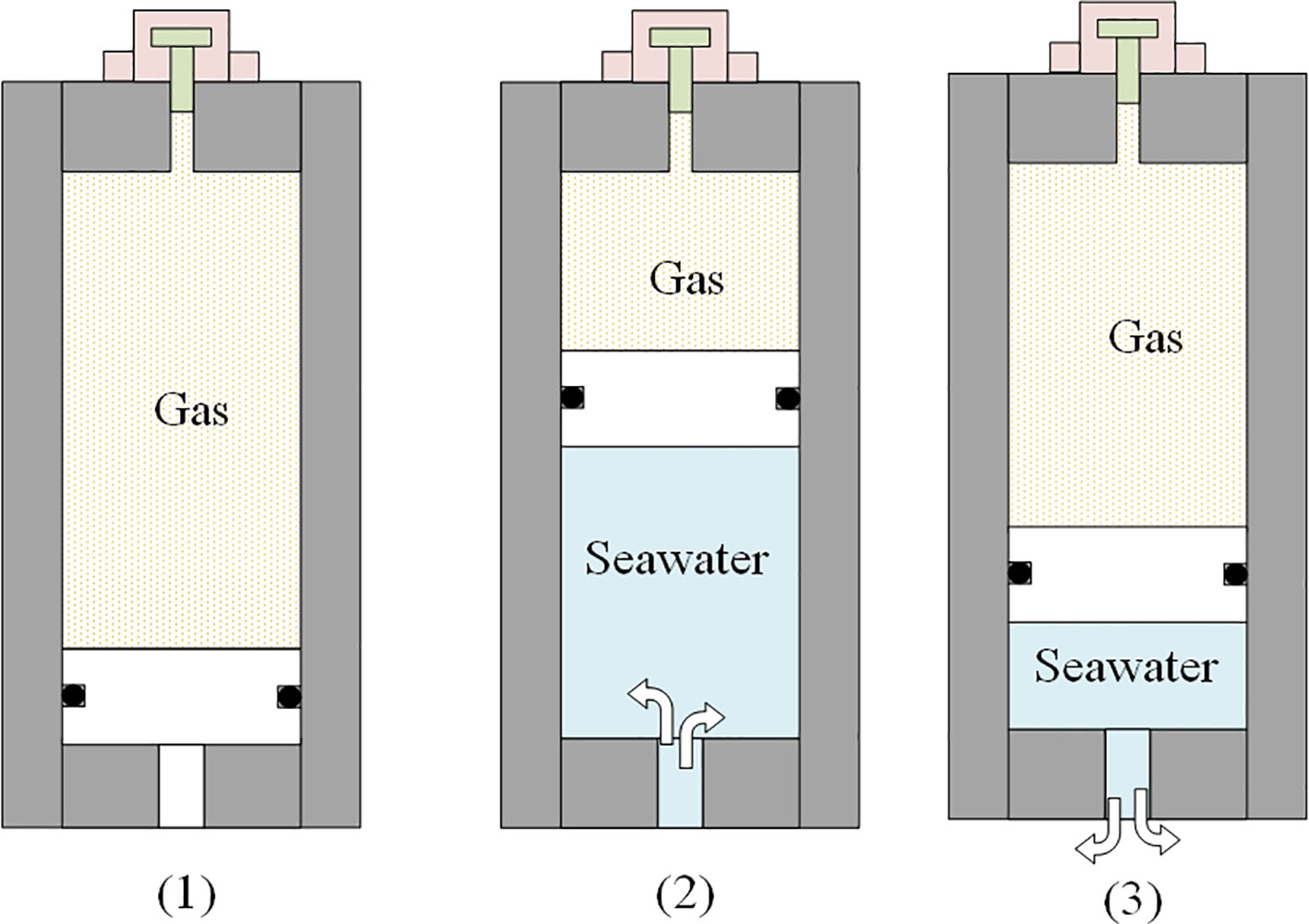
Figure 11 working process of a piston accumulator applied in isobaric sampling [(1): pre-charge state; (2): high pressure seawater gets into the accumulator and compresses the gas; (3): the high-pressure gas pushes some of the seawater return to the pressure vessel].
In general, the accumulator has the advantages of simple structure, lightweight and high efficiency, and it is a suitable choice for pressure compensation components used in isobaric sampling devices. However, there are still some problems in the design and evaluation of accumulators when applied in the deep sea. Firstly, safety is an important issue. With the application depth increases, the interior of the accumulator is filled with high-pressure gas, which is dangerous to operators. Secondly, as the operation depth increases, the compressibility of the gas decreases due to the existence of Van der Waals forces, which leads to a decrease in the volumetric efficiency of the accumulator, and an accumulator with a larger volume is required when the water depth increases. The ideal gas state equation is difficult to satisfy the requirements of application situations with higher pressures, although the equation has high accuracy below 30MPa. Many researchers have established the real gas state equations through theoretical derivation or experiments, but they still cannot accurately describe the gas’s properties under high or ultra-high pressure (Span et al., 2000; Mir Rajabi, 2006; Wang et al., 2020). Moreover, despite the simple structure of the accumulator, it is quite difficult to establish a mathematical model for quantitative analysis because this multi-phase system involves mechanics, thermodynamics, pneumatics and hydraulics, etc. Some researchers have established mathematical models to help us optimize the accumulator (Giliomee, 2007; Alatalo et al., 2018).
In addition, to adapt to the deep-sea application situation, many new structures have been designed, such as spring-loaded (Figure 12A) or weight-loaded (Figure 12B) accumulators, in anticipation of using force from spring deformation or gravity of heavy objects to replace high-pressure gas. Some accumulators use two pistons of different sizes to reduce the pressure in the spring chamber, but the volumetric efficiency is lower (Mir Rajabi, 2006) (Figure 12C). These new structures avoid the use of high-pressure gas and significantly improve the safety of deep-sea accumulators. However, they have not yet been used in deep-sea isobaric sampling.
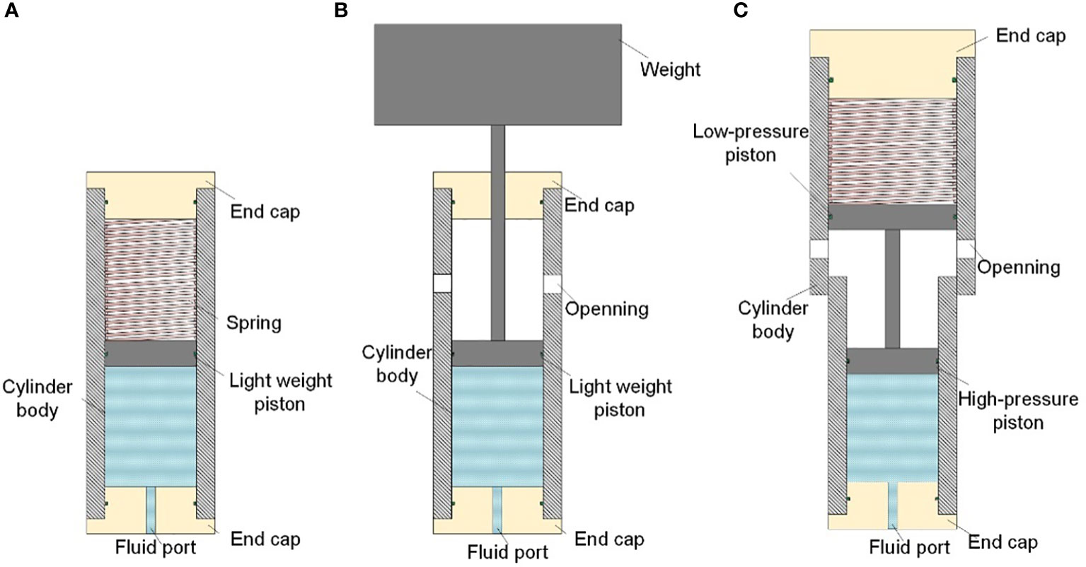
Figure 12 New structures of accumulators (A): Spring loaded accumulator; (B): Improved spring-loaded accumulator; (C) weight-loaded accumulator.
3.1.2 Semi-active pressure compensation technology
Based on the gas accumulator, semi-active pressure compensation uses some measures to improve the pressure retaining rate. For instance, the designer of PMTI equipped a submarine pressurizing pump connected to the pressure vessel via a capillary, mainly considering the effect of seal movement on the pressure drop. The seal can move axially within a specific range in the groove generally. When the sampler is recovered, the seal will be pushed towards the low-pressure side of the groove due to the reduction of external pressure, which increases the volume of the vessel and causes the pressure drop. The submarine pressurizing pump is an electric plunger pump used to establish the initial pressure difference between the vessel and seawater at the sea bed. Besides, it increases the initial contact pressure of the sealing ring and pushes the sealing ring to the low-pressure side of the groove as much as possible. After the sampler is closed on the seabed, the submarine pressurizing pump injects a specific volume of pure water into the vessel (Figure 13). Table 2 compares the pressure retaining performance of PMTI when passive and semi-active technology was adopted. Experiment results show that semi-active compensation method can significantly improve the pressure retaining rate even when water depth exceeds 6000m (Wang et al., 2022).
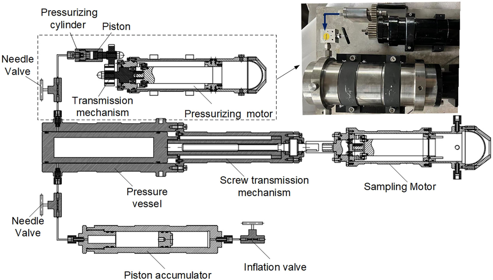
Figure 13 The pressurizing device of PMTI.
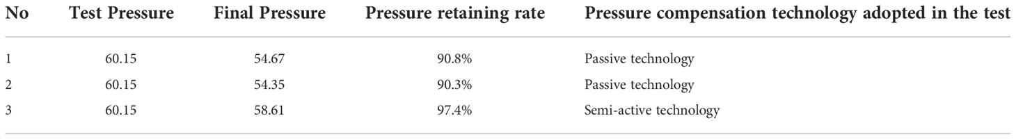
Table 2 Pressure retaining data of hyperbaric chamber of PMTI (data from Wang et al., 2022).
3.1.3 Active pressure compensation technology
Active pressure compensation technology adopts the liquid compensation method, and there are currently two practical application examples. The first is the PRD compensation device used in the PERISCOP sampling system (Figure 14), which includes a pressure vessel to store the sample, a double-valve mechanical pressure regulator, a reference container, and a reservoir container (with a pressure higher than that of the sampling depth). The reference container is closed at the sampling depth, and recorded the in-situ pressure. As the sampler ascends, the pressure regulator compares the pressure in the sample cell and the reference container. Once the pressure in the sample vessel is reduced, the pressure regulator will turn on the passage between the pressure vessel and the high-pressure seawater vessel and repressure the sample vessel until it is equal to the pressure in the reference vessel again.
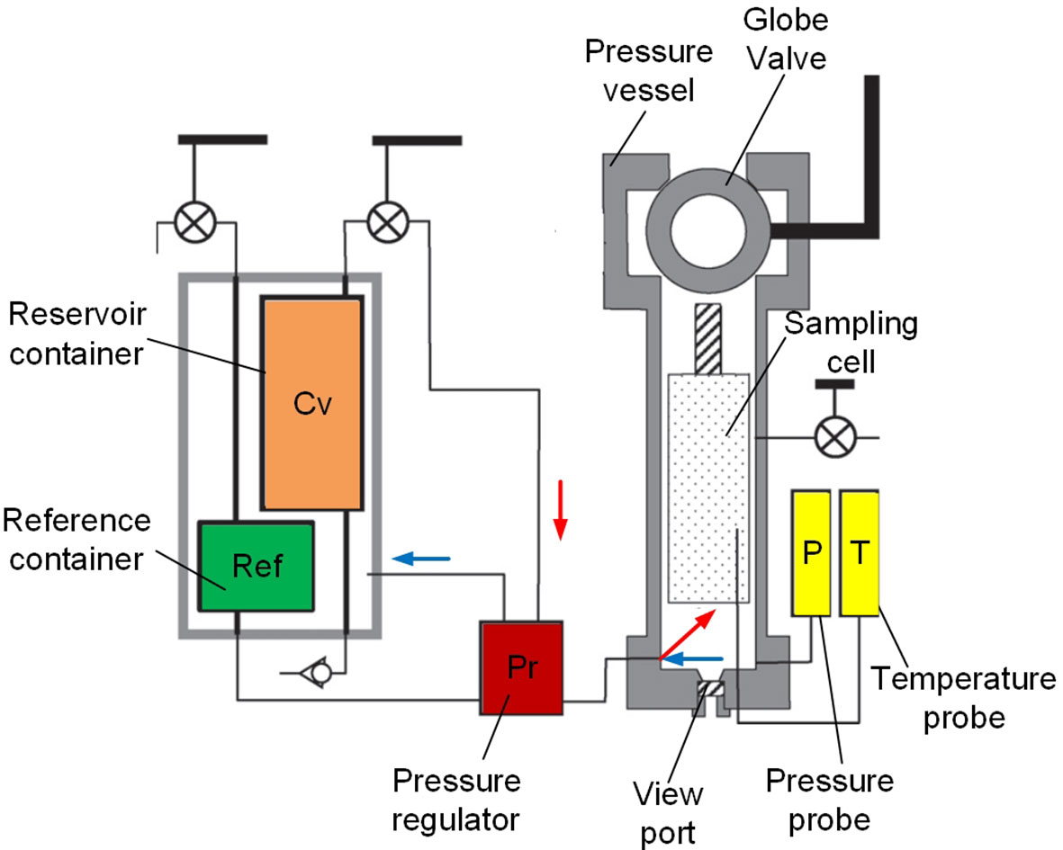
Figure 14 PRD of PERISCOP (Adapted from Shillito et al., 2008).
Another active pressure compensation device is applied to a deep-sea water serial sampler (Figure 15). The pressure compensation device of this sampler is based on an electric reciprocating plunger pump. The plunger pump, equipped with two one-way valves, is used for the inlet of seawater and the pressurizing channel, respectively. Pressure sensors are used to record the pressure of the sampling depth and the pressure value in the sample vessel for the control system to read and compare in real-time. When the pressure drop exceeds 0.5MPa, the booster pump injects water into the pressure vessel. The compensation device proved to have a satisfactory performance within 40MPa.
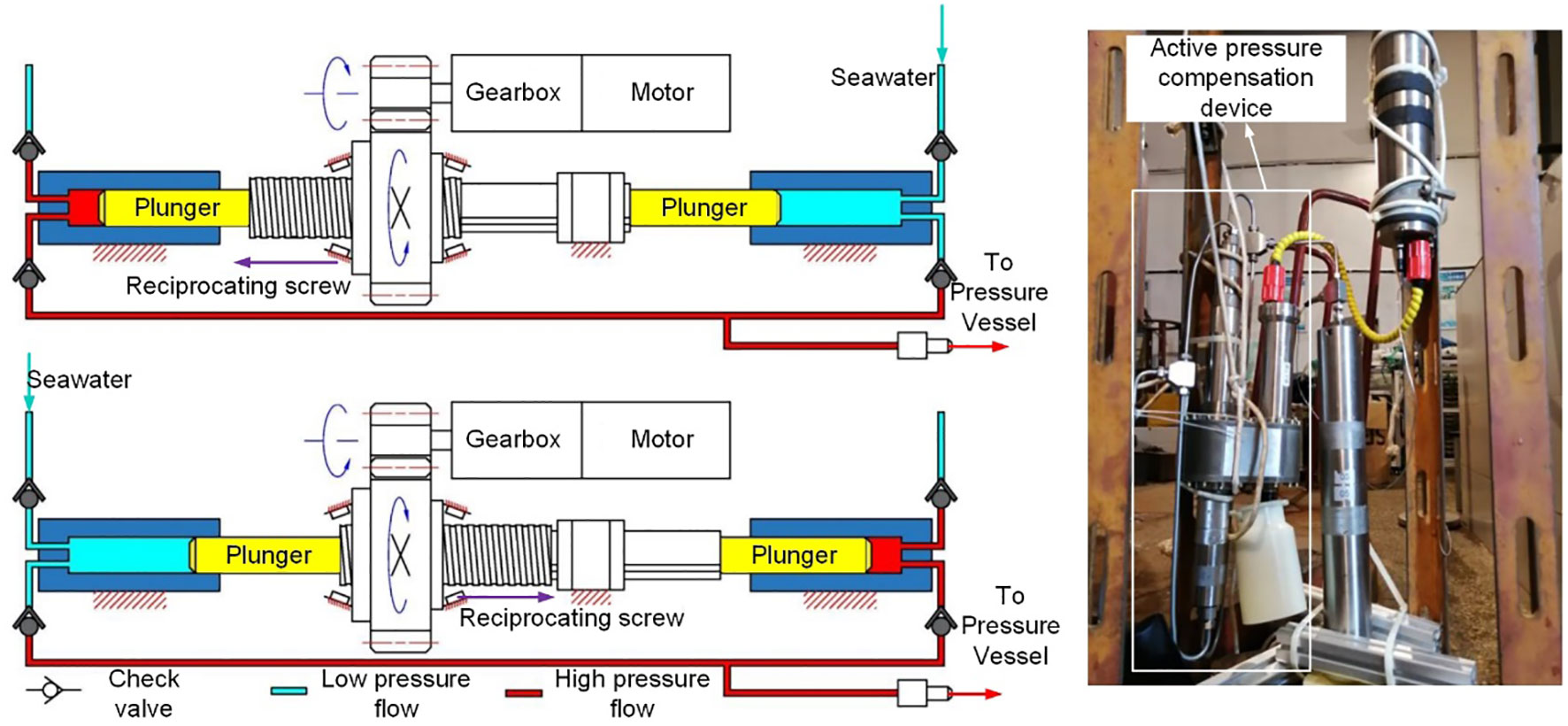
Figure 15 Active pressure compensation device (Adapted from Wang, 2020).
In general, passive pressure compensation technology is still the most widely applied technology, with a simple structure, low cost, and acceptable pressure-compensation performance. However, because of the use of high-pressure gas, the safety of passive pressure-holding technology is always a hidden problem during offshore operations. In addition, the volumetric efficiency of the gas accumulator decreases significantly as the operating depth increases. Currently, semi-active and active pressure compensation technologies are still not commonly used, primarily because the application of these technologies increases the system’s complexity and is more expensive. However, semi-active and active techniques are much safer, and we can precisely control the pressure of the sample by adopting these techniques.
3.2 Insulation
According to the World Ocean Atlas published by NOAA in the United States, the ocean’s temperature below 2500m is about 2°C-4°C, and it slowly rises to around 30°C on the surface. (https://data.nodc.noaa.gov/woa/WOA18/DATA/temperature/). It is necessary to take appropriate measures to maintain the temperature of the sample if the sampler stays on the surface for several hours. Here we divide the thermal insulation technologies of deep-sea samplers into passive and active thermal insulation.
3.2.1 Passive insulation
There are two methods for passive insulation. The first is to cover the vessel with thermal insulation layers. The second is to install an adiabatic sleeve out of the pressure vessel to form an annular insulation vacuum. Sometimes designers fill this space with water to provide a “water jacket.” Most of the samplers mentioned adopted passive insulation techniques. Thermal insulation materials used in deep-sea samplers usually have low thermal conductivity, anti-aging, high-pressure, low water absorption, and corrosion resistance and are lightweight. Commonly used insulation materials include polyurethane, polyvinyl chloride (PVC), polypropylene glass bead composite polyurethane (GSPU), Aerogel, etc. In addition, spraying insulation materials such as ZrO2/CaO, ZrO2-8% Y2O3 epoxy resin, etc., inside and outside the pressure vessel can reduce the radiant heat exchange (Di Girolamo et al., 2010). In some samplers, an insulation sleeve is installed outside the pressure vessel, and the annular space in between is filled with water or other refrigerants. For instance, liquid ammonia is filled in the annular space between the insulation barrel and the sample chamber (Zhu et al., 2011). The evaporation of liquid ammonia absorbs heat to keep the sample at a low temperature.
However, the effect of passive insulation is affected by many factors, such as the time staying on the surface, individual differences in materials, etc. and sometimes it does not achieve satisfactory results. For instance, the cod-end sampling system using a closed PVC tube for insulation. When it was recovered to the deck, the temperature increased to 11°C (the temperature of sampling depth is about 5°C and of tropical layer at surface is about 28°C) (Wild et al., 1985).The PERISCOPE system utilizes an insulation box made of syntactic foam to keep the samples cool. The temperature increased about 6°C after a 40min’ recovery operation (the temperature of surface water is about 25°C) (Shillito et al., 2008). However, it still is the most widely used insulation technology for deep-ocean samplers because of its simple structure and low cost.
3.2.2 Active insulation
Active insulation automatically adjusts the temperature in the sample chamber, which can keep the temperature within the desired range. Thermoelectric cooling technology is an active thermal insulation technology mainly applied to marine organisms. Wu et al. (2022) proposed an insulated organism sampler containing a pressure-adaptive thermoelectric cooler module and an automatic temperature control system (Figure 16). The cold end of the chilling semiconductor plate directly transmits the cold energy to the water in the sample chamber, while the heat at the hot end is dissipated by convection with seawater during the recovery process. All chilling semiconductor plates are encapsulated in a hose filled with insulating oil, and the pressure of the insulating oil is equal to the external environment pressure because of the elastic deformation of the hose. The device has been tested 4 times at a depth of 1000m-6000m, and the temperature change did not exceed 1°C. In addition, the PTCS system for gas hydrate established by Kawasaki et al. (2006) also applied thermoelectric cooling technology. Sun et al. (2015) proposed a novel gas hydrate sampler by injecting liquid nitrogen into a freezing chamber, and experiments proved that using liquid nitrogen as a freezing medium can improve thermal insulation performance.

Figure 16 Active insulation sampler [(A) Schematic diagram of the sampler; (B) Photo ofthe sampler]
Passive insulation technology can satisfy most deep-sea sampling requirements. However, for some special sampling situations, such as hydrothermal ports and deep-sea cold springs, passive insulation may cause excessive temperature changes. In principle, if the sampler stays on the surface for too long, the temperature of the sample will rise to the ambient temperature, which is disastrous for most deep-sea organisms. The advantage of active insulation lies in the temperature inside the sample chamber can be controlled at the in-situ temperature as long as there is a sufficient power supply.
3.3 Sealing
A reliable seal is a prerequisite for obtaining pressure-retaining samples. The sealing structures used for deep-sea animal pressure-retaining samplers can be divided into the following categories: ball valve, door sealing, and piston sealing.
Ball valves are widely used in industry and are a highly reliable sealing element. The spool of the ball valve is a sphere with a through hole, which is the passage for animals. When applied to deep-sea sampling, the disadvantage of the ball valve is its complex structure and heavy weight. The sealing principle of the ball valve determines its inherent geometric properties. The minimum diameter ratio of the ball and the through hole should be greater than 1.42. For example, an inlet with a diameter of 50mm requires a diameter of a sphere greater than 71mm. As the design pressure increases, the seat size will be significantly increased, which leads to the heavy weight of the ball valve. However, in depth is not very deep, and the large through-holes are not required. Using a ball valve is still an efficient and reliable sealing method. Recovery Apparatus, High-pressure trap, PERISCOP adopted ball valves.
Door sealing can be divided into inner and outer door sealing according to the position of the door works. Flap doors are the most commonly used form of door sealing. The flap door is sealed using a plate mounted inside the sample chamber to compress the inner face-mounted seal ring of the pressure chamber. The flap valve is fixed during sampling, and the sample can enter the pressure chamber. Once the release mechanism is triggered, the flap valve flips and compresses the seal ring installed on the end face (usually driven by a spring). Pressure Fish Trap, Hyperbaric Fish Trap, and Hyperbaric Trap Respirometer use flap door. The Pressure-stat Aquarium also adopts internal door sealing. The ROV pulls out the limit pin of the doors, and the two doors inside the vessel are pushed to the end face by springs. Unlike the flap valve, this door performs an axial movement rather than a rotary one. The Deep-water Trap uses an internal rotating drum that is pressed against the inner wall of the pressure vessel by four hydraulic cylinders. As the sampler rises, the pressure difference between the inside and outside increases, and the door is pressed on the sealing ring tighter. Compared with the ball valve seal, the internal door seal has a simpler structure, and its weight is less restricted by the depth and diameter, which makes it easier to be deployed in the deep sea. Nevertheless, the pressure vessel is usually designed with a larger diameter to accommodate the internal doors.
Sealing rings installed on the piston rod press the inner wall of the chamber and thus seal the vessel. Generally, the diameter of the piston is the size of the inlet channel of organisms. The PRAT uses a piston rod with O-rings installed on each end of the rod (Figure 17A). After releasing the counterweight, the piston moves axially under the drive of the spring, and the seal ring is compressed by the inner wall of the pressure vessel to form an initial seal. The ingenious design of PRAT prevents the piston from bearing the axial force caused by the internal pressure, and all the internal pressure acts on the pressure vessel. PIMT uses a specially designed hollow piston with two sealing rings on each end, which is in a long cylindrical shape with a long rectangular slot machined in the middle to keep the sample (Figure 17B). The advantage of piston sealing is its simple structure, which can accomplish sampling and sealing with the exact drive mechanism. In addition, piston-sealing structures will significantly simplify the structure of the device.
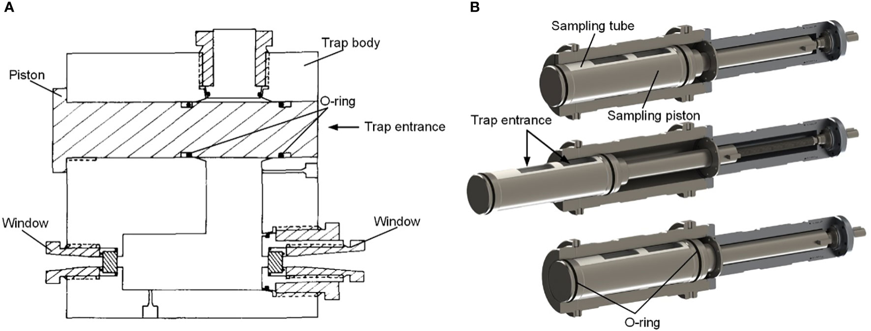
Figure 17 Piston sealing structure (A): sealing structure of PRAT [adapted from Yayanos, 1977)]; (B): sealing structure of PIMT [adapted from Wang et al., 2022)].
In general, as a sealing component, the ball valve is quite reliable. However, as mentioned above, its limitation is that it is cumbersome and inconvenient for offshore deployment. The door sealing structure is simpler and lighter. As the sampler rises, the door presses the seal tighter, so it is a self-tight sealing method. However, its disadvantage is the lack of seal reliability. This is because when the door is triggered, a spring presses the door against the seal on the end face of the vessel. When this seal structure is a flap door, it is driven by a torsion spring. In this case, the seal is not under uniform pressure from the door, so there may be a partial lack of initial contact stress on the sealing ring, resulting in seal failure. The piston seal is light and reliable. This is because the compression between the seal ring and the inner wall of the pressure vessel is fully capable of providing the initial contact pressure for sealing. Therefore, the piston seal is a better choice when other sampling operation requirements are satisfied.
4 Conclusion and prospects
The deep-sea macro organism fidelity samplers are indispensable investigation devices for marine biological research and biological resource development. Although countries worldwide have developed various samplers for over 100 years, it is still not enough. As marine science research goes into the deeper ocean, the requirements for organism samplers are also improving. Integration, intelligence, and diversification are the future development trends of marine sampling equipment. Specific to the deep-sea macro organism fidelity sampler, the purpose is to obtain higher-quality samples, carry out many complex physiological experiments, and obtain reliable data. Therefore, deep-sea macro-organisms sampling technology’s development prospects are discussed in the following two aspects.
(1) High fidelity, which means high pressure retaining rate and insulation rate while reducing adverse effects of human factors. It determines the scientific research value of the samples straightly. High fidelity is vital for organisms in unique environments, such as cold springs, hydrothermal fluids, hadals, etc. Therefore, accurate control of sample temperature and pressure will be a significant development direction of macro-organisms sampling equipment. As a result, active pressure compensation and insulation technology will be widely used.
(2) Function integration. It is necessary for marine organism science research to record videos and photos of living things at depth, measure the respiration rate of organisms, and even carry out some simple physiological experiments. Although there have been instruments that can realize one or several functions, they are insufficient. By integrating the fidelity sampler with these optical and electrochemical components, we can compare the physiological parameters of one or several organisms in situ and in the laboratory. One of the future development directions of deep-sea organism sampling is how to give more functions to the fidelity sampler.
Author contributions
Contributors HW mainly wrote most chapters of the paper. HW and JC summarized relevant literatures. HW and QZ drafted the manuscript. XH, JG, YW, and HL helped organize the manuscript. All authors contributed to the article and approved the submitted version.
Funding
The study based on the project named “Research on in-situ metabolic measurement and high-quality experimental technology in hadal amphipods”, which is derived from the “General projects of China National Natural Fund” (grant No 42276191) supporting by the China National Natural Fund Committee.
Conflict of interest
The authors declare that the research was conducted in the absence of any commercial or financial relationships that could be construed as a potential conflict of interest.
The reviewer HH declared a shared affiliation with the authors to the handling Editor at the time of review.
Publisher’s note
All claims expressed in this article are solely those of the authors and do not necessarily represent those of their affiliated organizations, or those of the publisher, the editors and the reviewers. Any product that may be evaluated in this article, or claim that may be made by its manufacturer, is not guaranteed or endorsed by the publisher.
References
Aguzzi J., Doya C., Tecchio S., De Leo F. C., Azzurro E., Costa C., et al. (2015). Coastal observatories for monitoring of fish behaviour and their responses to environmental changes. Rev. fish. Biol. fish. 25 (3), 463–483. doi: 10.1007/s11160-015-9387-9
Aguzzi J., Mànuel A., Condal F., Guillén J., Nogueras M., Del Rio J., et al. (2011). The new seafloor observatory (OBSEA) for remote and long-term coastal ecosystem monitoring. Sensors 11 (6), 5850–5872. doi: 10.3390/s110605850
Alatalo J., Liedes T., Pylvänäinen M. (2018). “Simulation model of a piston type hydro-pneumatic accumulator,” in Proceedings of the 9th EUROSIM congress on modelling and simulation, EUROSIM 2016, the 57th SIMS conference on simulation and modelling SIMS 2016, vol. 142. (Oulu, Finland: Linköping University Electronic Press), 235–242.
Bosley K. L., Bosley K. M., Keller A. A., Whitmire C. E. (2020). Relating groundfish diversity and biomass to deepsea corals and sponges using trawl survey catch data. Mar. Ecol. Prog. Ser. 646, 127–143. doi: 10.3354/meps13393
Brown D. M. (1975). “Four biological samplers: opening-closing midwater trawl, closing vertical tow net, pressure fish trap, free vehicle drop camera,” in Deep Sea research and oceanographic abstracts, vol. Vol. 22. (Elsevier), 565–567.
Cappo M., Harvey E., Shortis M. (2006). “Counting and measuring fish with baited video techniques-an overview,” in Australian Society for fish biology workshop proceedings, vol. Vol. 1. (Tasmania: Australian Society for Fish Biology), 101–114.
Chen H., Wang M., Li M., Lian C., Zhou L., Zhang X., et al. (2021). A glimpse of deep-sea adaptation in chemosynthetic holobionts: Depressurization causes DNA fragmentation and cell death of methanotrophic endosymbionts rather than their deep-sea bathymodiolinae host. Mol. Ecol. 30 (10), 2298–2312. doi: 10.1111/mec.15904
Clark M. R., Consalvey M., Rowden, A. A. (Eds.) (2016). Biological sampling in the deep sea (New Jersey, USA: John Wiley & Sons).
Crespo G. O., Dunn D. C., Reygondeau G., Boerder K., Worm B., Cheung W., et al. (2018). The environmental niche of the global high seas pelagic longline fleet. Sci. Adv. 4 (8), eaat3681. doi: 10.1126/sciadv.aat36
De Mendonça S. N., Metaxas A. (2021). Comparing the performance of a remotely operated vehicle, a drop camera, and a trawl in capturing deep-sea epifaunal abundance and diversity. Front. Mar. Sci. 8, 583. doi: 10.3389/fmars.2021.631354
Di Girolamo G., Blasi C., Schioppa M., Tapfer L. (2010). Structure and thermal properties of heat treated plasma sprayed ceria–yttria co-stabilized zirconia coatings. Ceramics. Int. 36 (3), 961–968. doi: 10.1016/j.ceramint.2009.10.020
Dixon D. R., Dixon L. R., Shillito B., Gwynn J. P. (2002). Background and induced levels of DNA damage in pacific deep-sea vent polychaetes: the case for avoidance. Cahiers. biologie. Mar. 43 (3/4), 333–336. doi: 10.21411/CBM.A.13F4BE08
Drazen J. C., Bird L. E., Barry J. P. (2005). Development of a hyperbaric trap-respirometer for the capture and maintenance of live deep-sea organisms. Limnol. Oceanogr.: Methods 3 (11), 488–498. doi: 10.4319/lom.2005.3.488
Fanelli E., Bianchelli S., Danovaro R. (2018). Deep-sea mobile megafauna of Mediterranean submarine canyons and open slopes: Analysis of spatial and bathymetric gradients. Prog. Oceanogr. 168, 23–34. doi: 10.1016/j.pocean.2018.09.010
Fang J., Zhang L., Bazylinski D. A. (2010). Deep-sea piezosphere and piezophiles: Geomicrobiology and biogeochemistry. Trends Microbiol. 18 (9), 413–422. doi: 10.1016/j.tim.2010.06.006
Favali P., Beranzoli L. (2009). EMSO: European multidisciplinary seafloor observatory. Nucl. Instruments. Methods Phys. Res. Section. A.: Accelerators. Spectrometers. Detectors. Associated. Equip. 602 (1), 21–27. doi: 10.1016/j.nima.2008.12.214
Garel M., Bonin P., Martini S., Guasco S., Roumagnac M., Bhairy N., et al. (2019). Pressure-retaining sampler and high-pressure systems to study deep-sea microbes under in situ conditions. Front. Microbiol. 10, 453. doi: 10.3389/fmicb.2019.00453
Giddens J., Turchik A., Goodell W., Rodriguez M., Delaney D. (2021). The national geographic society deep-sea camera system: A low-cost remote video survey instrument to advance biodiversity observation in the deep ocean. Front. Mar. Sci. 7, 601411. doi: 10.3389/fmars.2020.601411
Giliomee C. L. (2007). Analysis of a four state switchable hydro-pneumatic spring and damper system (Pretoria, South Africa: University of Pretoria).
Gooday A. J., Schoenle A., Dolan J. R., Arndt H. (2020). Protist diversity and function in the dark ocean–challenging the paradigms of deep-sea ecology with special emphasis on foraminiferans and naked protists. Eur. J. protistol. 75, 125721. doi: 10.1016/j.ejop.2020.125721
Hiis E., Stenhjem M., Pisarev G. I., Balakin B. V. (2019). “Theoretical and experimental study of hydraulic accumulator discharge,” in AIP conference proceedings, vol. Vol. 2116. (New York, USA: AIP Publishing LLC), 030031.
Jamieson A. J. (2018). A contemporary perspective on hadal science. Deep. Sea. Res. Part II.: Topical. Stud. Oceanogr. 155, 4–10. doi: 10.1016/j.dsr2.2018.01.005
Jamieson A. J., Fujii T., Solan M., Matsumoto A. K., Bagley P. M., Priede I. G. (2009). Liparid and macrourid fishes of the hadal zone: In situ observations of activity and feeding behaviour. Proc. R. Soc. B.: Biol. Sci. 276 (1659), 1037–1045. doi: 10.1098/rspb.2008.1670
Jamieson A. J., Stewart H. A., Weston J. N., Bongiovanni C. (2021). Hadal fauna of the south sandwich trench, southern ocean: Baited camera survey from the five deeps expedition. Deep. Sea. Res. Part II.: Topical. Stud. Oceanogr. 194, 104987. doi: 10.1016/j.dsr2.2021.104987
Jones D. O., Bett B. J., Wynn R. B., Masson D. G. (2009). The use of towed camera platforms in deep-water science. Underwater. Technol. 28 (2), 41–50. doi: 10.3723/ut.28.041
Jóźwiak P., Pabis K., Brandt A., Błażewicz M. (2020). Epibenthic sled versus giant box corer–comparison of sampling gears for tanaidacean species richness assessment in the abyssal benthic ecosystem. Prog. Oceanogr. 181, 102255. doi: 10.1016/j.pocean.2019.102255
Kawasaki M., Umezu S., Yasuda M. (2006). Pressure temperature core sampler (PTCS). J. Japanese. Assoc. Petroleum. Technol. 71 (1), 139–147. doi: 10.3720/japt.71.139
Koyama S. (2010). Development of high pressure research instrument for keeping of deep-Sea multicellular organisms. Rev. High Pressure Sci. Technol. 20 (4), 330-338. doi: 10.4131/jshpreview.20.330
Koyama S., Miwa T., Horii M., Ishikawa Y., Horikoshi K., Aizawa M. (2002). Pressure-stat aquarium system designed for capturing and maintaining deep-sea organisms. Deep. Sea. Res. Part I.: Oceanogr. Res. Papers. 49 (11), 2095–2102. doi: 10.1016/S0967-0637(02)00098-5
Lembke C., Grasty S., Silverman A., Broadbent H., Butcher S., Murawski S. (2017). The camera-based assessment survey system (C-BASS): a towed camera platform for reef fish abundance surveys and benthic habitat characterization in the gulf of Mexico. Continental. Shelf. Res. 151, 62–71. doi: 10.1016/j.csr.2017.10.010
Lins L., Brandt A. (2020). Comparability between box-corer and epibenthic-sledge data on higher taxon level: A case study based on deep-sea samples from the NW pacific. Prog. Oceanogr. 182, 102273. doi: 10.1016/j.pocean.2020.102273
Linse K., Anderson M. (2021). Macrobenthic Mollusca from prince Gustav channel and duse bay, Eastern Antarctic peninsula collected by epibenthic sledge in march 2018 (Southampton, UK: University of Southampton).
Macdonald A. (1972). High-pressure equipment for use in the laboratory, at sea and at depth. In Life at High Pressure (Springer, Cham).
Macdonald A. G., Gilchrist I. (1969). Recovery of deep seawater at constant pressure. Nature 222 (5188), 71–72. doi: 10.1038/222071a0
Macdonald A. G., Gilchrist I. (1978). Further studies on the pressure tolerance of deep-sea crustacea, with observations using a new high-pressure trap. Mar. Biol. 45 (1), 9–21. doi: 10.1007/BF00388973
Mir Rajabi M. (2006). The deep water gas charged accumulator and its possible replacements (Texas, USA: Texas A&M University).
Mortensen P. B., Roberts J. M., Sundt R. C. (2000). Video-assisted grabbing: a minimally destructive method of sampling azooxanthellate coral banks. J. Mar. Biol. Assoc. United. Kingdom. 80 (2), 365–366. doi: 10.1017/S0025315400001983
Murton B. J., Hühnerbach V., Garrard J. (2012). Exploring ultradeep hydrothermal vents in the Cayman trough by ROV. Sea. Technol. 53 (9), 15–18.
Phillips B. T., Licht S., Haiat K. S., Bonney J., Allder J., Chaloux N., et al. (2019). DEEPi: A miniaturized, robust, and economical camera and computer system for deep-sea exploration. Deep. Sea. Res. Part I.: Oceanogr. Res. Papers. 153, 103136. doi: 10.1016/j.dsr.2019.103136
Phleger C. F., McConnaughey R. R., Crill P. (1979)Hyperbaric fish trap operation and deployment in the deep sea. Deep. Sea. Res. Part A. Oceanogr. Res. Papers. 26 (12), 1405–1409. doi: 10.1016/0198-0149(79)90008-6
Pinho M., Medeiros-Leal W., Sigler M., Santos R., Novoa-Pabon A., Menezes G., et al. (2020). Azorean demersal longline survey abundance estimates: Procedures and variability. Regional. Stud. Mar. Sci. 39, 101443. doi: 10.1016/j.rsma.2020.101443
Prohaska B. K., Talwar B. S., Grubbs R. D. (2021). Blood biochemical status of deep-sea sharks following longline capture in the gulf of Mexico. Conserv. Physiol. 9 (1), coaa113. doi: 10.1093/conphys/coaa113
Przeslawski R., Berents P., Clark M., Edgar G., Frid C., Hughes L., et al. (2018). “Marine sampling field manual for grabs and box corers,” in Field manuals for marine sampling to monitor Australian waters (Australia: Marine Biodiversity Hub), 172–195.
Purser A., Marcon Y., Dreutter S., Hoge U., Sablotny B., Hehemann L., et al. (2018). Ocean floor observation and bathymetry system (OFOBS): A new towed camera/sonar system for deep-sea habitat surveys. IEEE J. Oceanic. Eng. 44 (1), 87–99. doi: 10.1109/JOE.2018.2794095
Ramirez-Llodra E., Brandt A., Danovaro R., De Mol B., Escobar E., German C. R., et al. (2010). Deep, diverse and definitely different: unique attributes of the world’s largest ecosystem. Biogeosciences 7 (9), 2851–2899. doi: 10.5194/bg-7-2851-2010
Ravaux J., Hamel G., Zbinden M., Tasiemski A. A., Boutet I., Léger N., et al. (2013). Thermal limit for metazoan life in question: in vivo heat tolerance of the pompeii worm. PloS One 8 (5), e64074. doi: 10.1371/journal.pone.0064074
Sandulli R., Ingels J., Zeppilli D., Sweetman A. K., Hardy Mincks S., Mienis F., et al. (2021). Extreme benthic communities in the age of global change. Front. Mar. Sci. 7, 609648. doi: 10.3389/fmars.2020.609648
Shillito B., Hamel G., Duchi C., Cottin D., Sarrazin J., Sarradin P. M., et al. (2008). Live capture of megafauna from 2300 m depth, using a newly designed pressurized recovery device. Deep. Sea. Res. Part I.: Oceanogr. Res. Papers. 55 (7), 881–889. doi: 10.1016/j.dsr.2008.03.010
Smith K.L., Baldwin R. J. (1997). “9 laboratory and in situ methods for studying deep-Sea fishes,” in Fish physiology, vol. Vol. 16. (Amsterdam, Netherlands: Academic Press), 351–378.
Smith K. L., Brown N. O. (1983). Oxygen consumption of pelagic juveniles and demersal adults of the deep-sea fish sebastolobus altivelis, measured at depth. Mar. Biol. 76 (3), 325–332. doi: 10.1007/BF00393036
Somero G. N. (1992). Adaptations to high hydrostatic pressure. Annu. Rev. Physiol. 54 (1), 557–577. doi: 10.1146/annurev.ph.54.030192.003013
Span R., Lemmon E. W., Jacobsen R. T., Wagner W., Yokozeki A. (2000). A reference equation of state for the thermodynamic properties of nitrogen for temperatures from 63.151 to 1000 K and pressures to 2200 MPa. J. Phys. Chem. Reference. Data 29 (6), 1361–1433. doi: 10.1063/1.1349047
Sun Y., Wang Y., Lü X., Jia R., Guo W. (2015). Hole-bottom freezing method for gas hydrate sampling. J. Natural Gas. Sci. Eng. 25, 271–283. doi: 10.1016/j.jngse.2015.05.011
Teoh Z. E., Phillips B. T., Becker K. P., Whittredge G., Weaver J. C., Hoberman C., et al. (2018). Rotary-actuated folding polyhedrons for midwater investigation of delicate marine organisms. Sci. Robotics. 3 (20), eaat5276. doi: 10.1126/scirobotics.aat5276
Thurber A. R., Sweetman A. K., Narayanaswamy B. E., Jones D. O., Ingels J., Hansman R. L. (2014). Ecosystem function and services provided by the deep sea. Biogeosciences 11 (14), 3941–3963. doi: 10.5194/bg-11-3941-2014
Vogt D. M., Becker K. P., Phillips B. T., Graule M. A., Rotjan R. D., Shank T. M., et al. (2018). Shipboard design and fabrication of custom 3D-printed soft robotic manipulators for the investigation of delicate deep-sea organisms. PLS. One 13 (8), e0200386. doi: 10.1371/journal.pone.0200386
Wang S. (2020). Research on the mechanism and key technology of accurate pressure-maintaining fluid sampling in full ocean depthPhD Thesis.
Wang H., Chen J., Cao C., Ge Y., Fang J., Zhou P., et al. (2022). Capturing amphipods in the Mariana trench with a novel pressure retaining sampler. Deep. Sea. Res. Part I.: Oceanogr. Res. Papers. 184, 103772. doi: 10.1016/j.dsr.2022.103772
Wang H., Chen J., Wang Y., Fang J., Fang Y. (2020). Research and analysis of pressure-maintaining trapping instrument for macro-organisms in hadal trenches. J. Mar. Sci. Eng. 8 (8), 596.
Wang S., Wu S., Du M., Yang C., Wang X. (2020). A new serial sampler for collecting gas-tight samples from seafloor cold seeps and hydrothermal vents. Deep. Sea. Res. Part I.: Oceanogr. Res. Papers. (Hangzhou, China; Zhejiang University) 161, 103282. doi: 10.1016/j.dsr.2020.103282
White S. N., Brewer P. G., Peltzer E. T., Kirkwood W., Pasteris J. D., Nakayama N. (2003). “First expeditionary deployments of the deep ocean raman in situ spectrometer,” in AGU fall meeting abstracts (USA: American Geophysical Union, California), Vol. 2003. OS32A–O0235.
Wild R. A., Darlington E., Herring P. J. (1985)An acoustically controlled cod-end system for the recovery of deep-sea animals at in situ temperatures. Deep. Sea. Res. Part A. Oceanogr. Res. Papers 32 (12), 1583–1589 doi: 10.1016/0198-0149(85)90104-9
Wilson R.R., Smith K.L. (1985)Live capture, maintenance and partial decompression of a deep-sea grenadier fish (Coryphaenoides acrolepis) in a hyperbaric trap-aquariumDeep. Sea. Res. Part A. Oceanogr. Res. Papers. 32 (12), 1571–1582. doi: 10.1016/0198-0149(85)90103-7
Wu S. J., Wang X., Wang S., Zhang B., Yang C. J., Zhi H. (2022). Active temperature-preserving deep-sea water sampler configured with a pressure-adaptive thermoelectric cooler module. Deep. Sea. Res. Part I.: Oceanogr. Res. Papers. 181, 103701. doi: 10.1016/j.dsr.2022.103701
Yan G., Lan Y., Sun J., Xu T., Wei T., Qian P. Y. (2022). Comparative transcriptomic analysis of in situ and onboard fixed deep-sea limpets reveals sample preparation-related differences. Iscience 25 (4), 104092. doi: 10.1016/j.isci.2022.104092
Yayanos A. A. (1977). Simply actuated closure for a pressure vessel: design for use to trap deep-sea animals. Rev. Sci. Instruments. 48 (7), 786–789. doi: 10.1063/1.1135150
Yayanos A. A. (1978). Recovery and maintenance of live amphipods at a pressure of 580 bars from an ocean depth of 5700 meters. Science 200 (4345), 1056–1059. 10.1126/science.200.4345.1056
Yayanos A. A. (2009). Recovery of live amphipods at over 102 MPa from the challenger deep. Mar. Technol. Soc. J. 43 (5), 132–136. doi: 10.4031/MTSJ.43.5.20
Zaharina E., Abramchuk M., Perepelkina S. Y. (2020). “Development of the hyperbaric chamber for capturing and studying deep-Sea creatures,” in International Russian automation conference (Cham: Springer), 956–966.
Keywords: isobaric sampling, deep-sea animals, pressure compensation, insulation, sealing
Citation: Wang H, Chen J, Zhou Q, Hu X, Gao Q, Guo J, Wang Y and Li H (2022) Isobaric sampling apparatus and key techniques for deep sea macro-organisms: A brief review. Front. Mar. Sci. 9:1071940. doi: 10.3389/fmars.2022.1071940
Received: 17 October 2022; Accepted: 02 November 2022;
Published: 23 November 2022.
Edited by:
Simone Marini, National Research Council (CNR), ItalyReviewed by:
Atmanand M. A., Indian Institute of Technology Madras, IndiaWang Minxiao, Institute of Oceanology (CAS), China
Haocai Huang, Zhejiang University, China
Copyright © 2022 Wang, Chen, Zhou, Hu, Gao, Guo, Wang and Li. This is an open-access article distributed under the terms of the Creative Commons Attribution License (CC BY). The use, distribution or reproduction in other forums is permitted, provided the original author(s) and the copyright owner(s) are credited and that the original publication in this journal is cited, in accordance with accepted academic practice. No use, distribution or reproduction is permitted which does not comply with these terms.
*Correspondence: Jiawang Chen, YXJ3YW5nQHpqdS5lZHUuY24=
†ORCID: Jiawang Chen, orcid.org/0000-0002-6351-0062