 Jiajun Hu
 Hanwen Zhang1
 Lianhui Wu
 Fukun Gui
95% of researchers rate our articles as excellent or good
Learn more about the work of our research integrity team to safeguard the quality of each article we publish.
Find out more
ORIGINAL RESEARCH article
Front. Mar. Sci. , 07 November 2022
Sec. Marine Fisheries, Aquaculture and Living Resources
Volume 9 - 2022 | https://doi.org/10.3389/fmars.2022.1035794
This article is part of the Research Topic Aquaculture Environment Regulation and System Engineering View all 18 articles
The optimization of the inlet layout in aquaculture systems is essential to ensure minimal solid waste discharge into the environment and improve fish production efficiency. In the present study, laboratory experiments were carried out to investigate the effects of the jetting position d/a (where d is the distance from the pipe axis to the tank side and a is the side length of the tank wall) and the jetting angle θ (the acute angle between the jetting direction and the nearest tank wall) on the solid waste removal efficiency in single-inlet and dual-inlet octagonal Recirculating Aquaculture System (RAS) tanks. To this end, three jetting positions (d/a) of 1/50, 1/8, and 1/4 and ten jetting angles (θ) of 0° to 80° were considered in the experiments. The Particle Image Velocimetry (PIV) technique was applied to measure the flow characteristics in the tank and analyze the solid waste removal under different working conditions. Residual mass of the solid waste, time of complete removal of solid waste, average velocity (vavg), and uniformity coefficient of velocity distribution (DU50) were analyzed to evaluate the solid waste removal efficiency. The obtained results indicate that adjustments of the inlet layout significantly affect the solid waste removal efficiency. It was found that a single-inlet tank with a d/a of 1/8 and θ in the range 10° to 40° has a good solid wastes removal performance, and the optimal efficiency occurs at a jetting angle of 30°. Moreover, the optimal solid waste removal efficiency in a dual-inlet tank can be achieved with a d/a ratio of 1/8 and a θ of 20°. The performed analyses reveal that from the aspect of solid waste removal efficiency, a tank with a d/a ratio of 1/8 outperforms a tank with a d/a ratio of 1/4 or 1/50. The results of this article offer novel insights in the layout of octagonal RAS tanks and provide a guideline to improve self-cleaning features of aquaculture tanks.
Studies show that China’s aquaculture industry has increased steadily in the past few decades. In 2021, China’s aquatic and aquaculture products exceeded 67 million and 54 million, respectively (Fisheries and Fishery Administration Bureau of the Ministry of Agriculture and Rural Zones et al., 2022). Despite these promising data, the traditional aquaculture development model is a challenge for the stringent environmental requirements, the safety of aquatic food, and the development of aquaculture (Zhang et al., 2017). Recently, Recirculating Aquaculture System (RAS) has been proposed as an advanced aquaculture method with remarkable advantages to optimize the water consumption in the aquaculture industry and improve the efficiency of aquaculture and land utilization. Studies show that RAS has made great progress in water disinfection, water purification, and the physiological and biochemical metrics in the aquaculture industry (Timmons et al., 1998). The performed analyses revealed that rapid solid waste flushing out of RAS tanks is an essential prerequisite to achieve an appropriate hydrodynamic performance and fish welfare (Gorle et al., 2020). In this scheme, different inlet layouts affect the solid waste removal efficiencies. However, considering the current shortcomings of a rational-based design on inlet layout on the solid waste removal efficiency of octagonal RAS tanks, conventional systems in the aquaculture industry is largely relying on previous experience. Therefore, it is necessary to systematically optimize the inlet layout to form an appropriate aquaculture flow field environment while improving the removal efficiency.
Duarte et al. (2011) showed that the tank geometry significantly affects the overall flow pattern. Generally, aquaculture tanks are fabricated in five geometries, including rectangular, circular, octagonal, rectangular round chamfering, and runway. Among these geometries, octagonal tanks are easier to handle and construct than other tanks so that octagonal tanks have been more common in operational production (Zhao et al., 2022). Davidson and Summerfelt (2004) studied the effects of the inlet structure on the self-cleaning features of large circular aquaculture tanks and found that the appropriate direction of the inlet structure increases the rotation velocity in the tank. Moreover, Zhu et al. (2022) conducted experiments and studied the removal of solid wastes, and analyzed the flow field in a circular aquaculture tank with different inlet layouts. It was found that adjusting the inlet layout would affect the flow field characteristics and the solid waste removal efficiency. Venegaset et al. (2014) systematically evaluated the effect of different water injection devices on the tangential velocity of flow in octagonal RAS tank. Benoit (2007) showed that the structure of the water inlet and outlet systems significantly affects the hydraulic mixing performance and the flushing ability of precipitated particles in the tank. In addition to experiments, numerical techniques have been widely applied to analyze the flow field and improve solid waste removal efficiency (Xue et al., 2020; Ren et al., 2021). Gorle et al. (2018a) studied the use of wall drain to control flow patterns in the tank. It was found that flow features such as pressure, velocity, uniformity, and turbulence affect the flow pattern so these features should be further investigated. The octagonal RAS tank is a common culture tank with good space management, shared side walkways, and homogeneous fluid mixing, which is widely used in aquaculture farms. Considering the production and welfare of animals in intensive aquaculture, the design and application of octagonal tanks should be given more attention in future research (Xue et al., 2021; Zhao et al., 2022). However, there is no in-depth investigation of the effects of inlet layout on the performance of octagonal RAS tanks.
Based on the performed literature survey, the main objective of the present study is to investigate the influence of inlet layout on the solid waste removal efficiency of octagonal tanks and measure the flow field distribution to explore the hydrodynamic feature of the tank. In this respect, the effects of numerous parameters, including the inlet mode, inlet angle, and inlet position on the efficiency of solid waste removal are investigated comprehensively to maximize the water conservancy conditions. This article is organized in five sections. After introducing the problem and a review of the literature, materials and methods and the experimental setup are discussed in Section 2. The Influence of the inlet layout on the solid waste removal efficiency, hydrodynamic characteristics, and flow patterns are presented in Section 3. Then the obtained results are analyzed to achieve an insight into the mixing phenomenon and the discussions are presented in Section 4. Finally, the main conclusions are summarized in Section 5.
In the present study, experiments were carried out using a RAS system consisting of an octagonal aquaculture tank model, a recirculating system, and a measurement system. During the experiments, solid waste removal (Figure 1A) and PIV flow field (Figure 1B) were studied. The tank model is made of transparent acrylic sheets and the dimensions of the test setup are presented in Figure 2. The tank model has a total side length of a = 100 cm and a height of 60 cm. Lekang (2013) demonstrated that optimal performance in an octagonal tank is achieved with a ratio of total side length to the corner side length of 5. Accordingly, four rectangular acrylic baffles with a height of 60 cm and a width of 28.28 cm were installed in four corners to form the octagonal aquaculture tank. The tank bottom was flat and a drain hole with a diameter of 4 cm was set in the tank center. The inlet pipe had a closed lower end and delivered water into the tank through 3 nozzles with a diameter of 2 cm. The diameter of nozzles were 0.6 cm and the distance of each nozzle from the end of the pipe was 2, 16.5, and 31 cm, respectively.
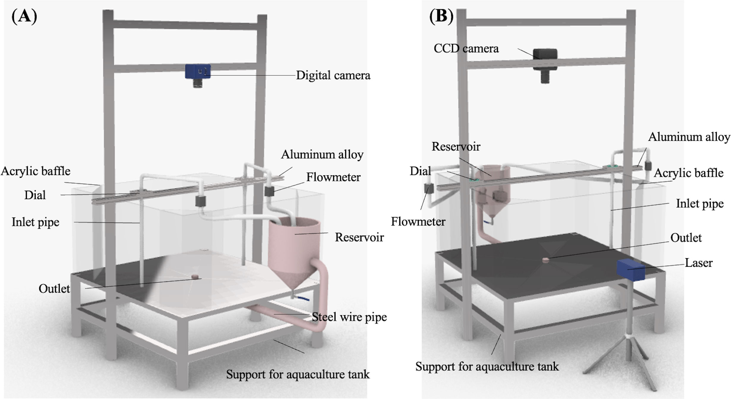
Figure 1 Configuration of the experiment setup: (A) Solid waste removal system; (B) PIV flow field measurement system.
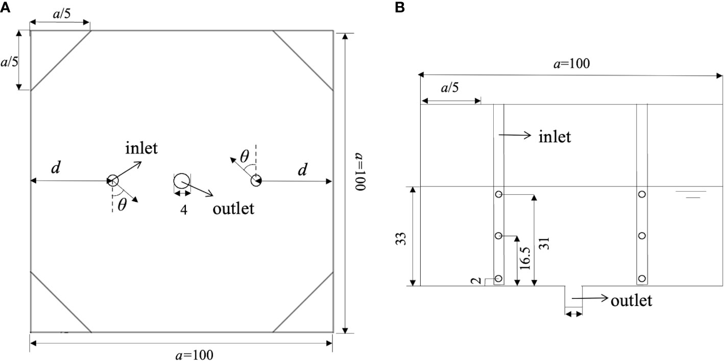
Figure 2 Configuration of the octagonal aquaculture tank: (A) Top view; (B) Front view (Unite: cm).
Figure 3 shows that the recirculation system mainly consists of a reservoir (Figure 3A), pipes, and a 55 W water pump (Sensen HQB-2500, China) (Figure 3B). The tank water runs into the reservoir through the connecting tube and then returns to the tank using the water pump, creating a water recirculation system. The measurement system is schematically presented in Figure 3C. A flowmeter (Keyence FD-Q20C, Japan) and a valve are installed vertically on the water inlet pipe to monitor and adjust the real-time input flow rate (L/min) into the aquaculture tank to guarantee the hydraulic residence time (HRT) of 30 min approximately (the water exchange rate is 2 times/h). Note that the input flow rate was set constant during the experiments so as to isolate its coupled effects with jetting configuration. Thus, the effect of jetting configuration on solid waste removal can be comprehensively figured out. An inlet assembly (Figure 3D) was designed to adjust the inlet layout and the jetting angle was measured by a dial (Figure 3E). Moreover, a digital camera (Nikon P7100, Japan) was installed over the tank to capture the distribution of solid wastes in the tank bottom. To this end, the surface of the bottom layer was covered with a white architectural film to increase the contrast between solid wastes and the background layer and improve the accuracy of the analysis. Based on related previous studies (Patterson et al., 1999; Du et al., 2020; Davidson and Summerfelt, 2004; Sin et al., 2021; Xue et al., 2022), cylindrical-shaped feed with a diameter of 1.4 mm, a length of 2.0 to 2.5 mm and a density of 1.3 g/cm3 were used to study the motions of settable solid waste such as uneaten feed and fish feces in the tank. The flow velocity was measured using the PIV system, which consists of a CCD camera, a laser device, and some particle tracers. In order to improve the quality of PIV images, black paint was sprayed on the bottom surface to eliminate undesired background light. In all experiments, tap water was used and the tank was filled to a depth of 33 cm to achieve a diameter-to-depth ratio of 1:3 and meet the design requirement for water depth (Lekang, 2013; Summerfelt et al., 2016).
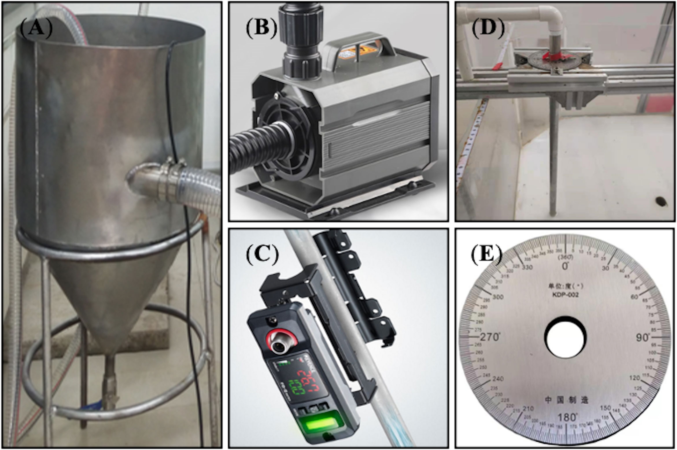
Figure 3 Main components of the experiment: (A) Reservoir; (B) Water pump; (C) Flowmeter; (D) Inlet assembly; (E) Dial.
In the present study, the influence of inlet mode, inlet jetting angle, and inlet jetting position on the octagonal aquaculture tank were analyzed comprehensively. It should be indicated that the inlet mode refers to the number of inlet pipes. In this regard, an inlet system with one pipe and two pipes is hereafter called single inlet mode and dual inlet mode, respectively. Moreover, the jetting angle refers to the acute angle between the jetting direction and the nearest tank wall. Therefore, the jetting angles of 0° and 90° are parallel and perpendicular to the nearest wall of the tank, respectively. Ten jetting angles of 0°, 10°, 20°, 30°, 40°, 45°, 50°, 60°, 70° and 80° were analyzed in the experiments. Particularly, the angle of 45° is also included for it is widely used in aquaculture practices (An et al,. 2018; Gorle et al., 2018b; Dauda et al., 2019). The jetting position refers to the position of the inlet pipe which is deployed in the tank. This parameter is reflected by d/a, where d is the distance from the pipe axis to the tank side. Based on the inlet pipe deployments that are commonly used in aquaculture practices, three jetting positions of d/a= 1/50, 1/8, and 1/4 were considered in the experiments. It should be indicated that when d/a= 1/50, the inlet pipe is just next to the tank wall. Further details of the experiment will be discussed in the following section.
Experiments were carried out in a laboratory-scale octagonal aquaculture tank in National Engineering Research Center for Marine Aquaculture, Zhoushan, China. The experimental procedures can be summarized as follows:
The experimental cases can be categorized into single-inlet and dual-inlet cases. In each mode, three jetting positions (d/a) of 1/50, 1/8, and 1/4 and ten jetting angles of 0°, 10°, 20°, 30°, 40°, 45°, 50°, 60°, 70°, and 80° were considered. In total, 60 cases were analyzed in this section and each case was tested triple. A four-step framework was established to perform the experiments.
(1) Adjust the inlet layout of the jetting mode, jetting position, and jetting angle for each case. (2) Adjust the water level in the tank and turn on the water pump to circulate water. After 30 minutes and achieving a steady-state condition, switched on the camera and settable feed (10 g) was evenly sprinkled into the tank as quickly as possible. Moreover, run the stopwatch to measure time. (3) Monitor the removal process of solid wastes by manual visual inspection. Based on previous studies (Summerfelt et al., 2016; Xue et al., 2022), the maximum monitoring time is set to 30 minutes. If the solid wastes are not drained completely after 30 minutes, the experimental system will be stopped and the residual solid waste will be collected by siphon, and the solid waste will be dried in the oven and weighted. On the other hand, if the solid waste removal process is completed in less than 30 minutes, the experiment will be stopped whenever the solid waste removal is completed. (4) Analyze the solid waste removal process using the captured images and compare the weight of the residual solid waste (Figure 4).
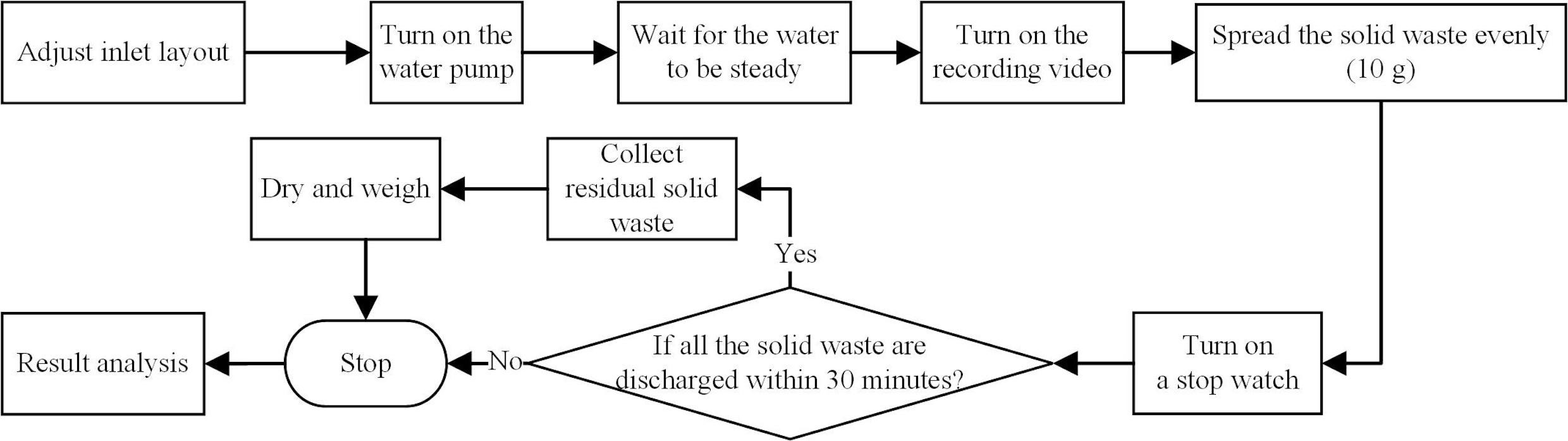
Figure 4 Flowchart of solid waste removal experiment.
In the experiment, the PIV technique was applied to measure the flow characteristics in the tank and investigate the solid waste removal mechanism under different working conditions. It is worth noting that the PIV technique gives quantitative information about the transient flow and is the most widely used flow velocity measurement technology in the field of experimental fluid mechanics (Robinson, 1991). Compared with single-point measuring instruments, the PIV technique can be applied to measure instantaneous flow fields without interference.
The measurements were carried out in a dark room in the Marine Measurement Laboratory of Qingdao Optical Flow Software Technology Co., Ltd, China. The main procedures of the PIV flow field experiment are consistent with those of the solid waste removal experiment (Figure 5). However, no solid waste was sprinkled into the aquaculture tank during the experiment due to the following facts: (1) Solid waste in the tank for a long time will affect the water clarity, thereby weakening the penetration degree of the laser and affecting the PIV results; (2) Solid waste has very little effect on the flow field. Since the removal of solid wastes is closely related to the bottom flow field, a CCD camera (5120 × 3800 pixels, 16 fps max) was deployed just above the tank to capture the tracer particles on the horizontal bottom layer. Accordingly, flow velocity contours and streamline patterns were obtained to analyze hydrodynamic parameters and flow field distributions. The captured images were preliminary processed using Flow pattern tracking master V50 software (Qingdao Optical Flow Software Technology Co., Ltd.) and then they were refined in the MATLAB (R2020b) platform to thoroughly analyze flow velocity and visualize the captured data. Figure 6 shows the obtained results in this respect.
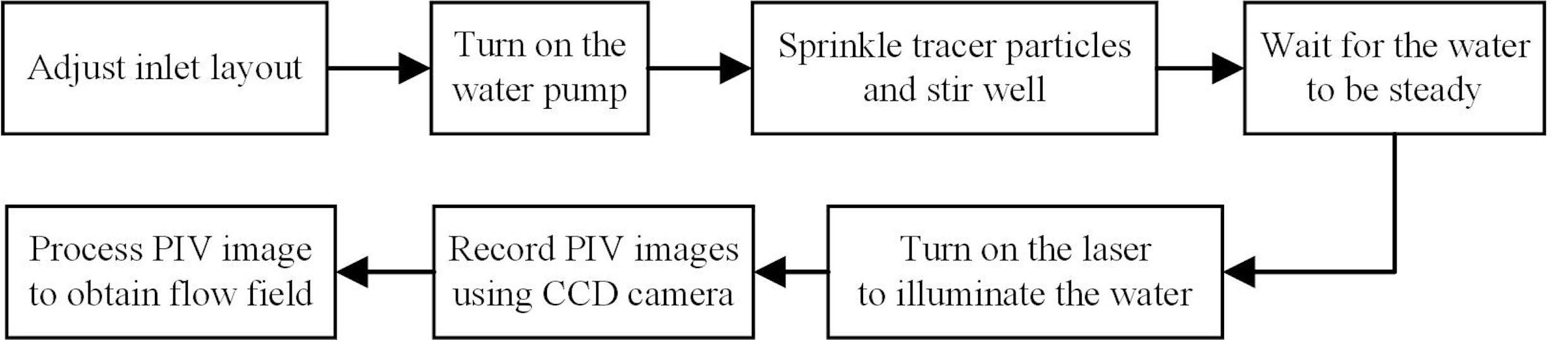
Figure 5 Flowchart of the flow field measurement experiment.
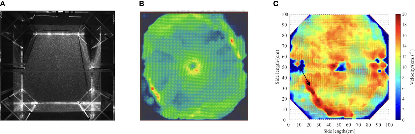
Figure 6 Image processing of PIV data: (A) Raw PIV image; (B) Preliminary treatment; (C) Refined treatment.
A review of the literature indicates that different optimal velocities have been proposed to maximize the health and growth of fish in the aquaculture industry (Oca et al., 2007; Masaló et al., 2016; Wang, 2019). Generally, fish incline to swim in water with high dissolved oxygen. Accordingly, heterogeneous distribution of dissolved oxygen promotes fish aggregation due to higher spontaneous activity, which increased the risk of wound infection. Therefore, rapid solid waste flushing out of the culture tanks is an important prerequisite to increase fish welfare and aquaculture yield.
Average velocity (vavg) and uniformity coefficient of velocity distribution (DU50) were comprehensively analyzed to evaluate the solid waste removal efficiency. To this end, the effects of the inlet layout on the homogeneity of water velocity were determined using Eq. (1) (Masaló and Oca, 2007; Masaló and Oca, 2010; Masaló and Oca, 2014). In this equation, DU50 is a parameter to adjust the average velocity of a specific tank to meet the self-cleaning requirements and reach the desired distribution of the dissolved oxygen. The average velocity (vavg) was measured using the PIV technique. It should be indicated that DU50 and vavg can be mathematically expressed in the form below (Venegas et al., 2014):
where v50 is the average velocity of the first 50% measured values at each point and vavg is the average weighted velocity of 9240 points of a depth section, which can be measured by the PIV technique. Meanwhile, vi is the velocity of the monitoring point, ri denotes the distance from the monitoring point to the tank center, and i is the number of cross-sectional monitoring points at a certain depth.
Figure 7 shows that in some cases, the solid wastes can be discharged completely within 30 minutes, while the complete discharge does not occur in other cases. Obviously, the cases with complete discharge have higher performance in self-cleaning. In the present study, a systematic comparison was carried out between all the experimental cases, the incomplete removal cases were also analyzed based on the residual mass in the aquaculture tank.

Figure 7 Samples of (A) complete and (B) incomplete solid waste removal processes within 30 minutes.
Figure 8 shows the time taken for complete solid removal. It is reminded that complete removal of solid waste does not occur in all cases. The horizontal and vertical axis represent the jetting angle and the corresponding time for complete solid removal. This figure does not cover the cases in which the solid waste removal does not complete in 30 minutes. It is observed that in the tank with a single inlet and d/a of 1/50 and 1/8, the time taken for the complete removal of solid waste increases with an increase in the jetting angle. The minimum evacuation time occurs at the jetting angles of 10° and 40°. Figure 8A indicates that when d/a is set to 1/4 and θ increases from 10° to 45°, all solid wastes are discharged from the aquaculture tank, and the optimal solid waste removal efficiency occurs at the jetting angle of 10°. Figure 8B reveals that in a tank with dual inlets and d/a of 1/50, the lowest solid waste removal time can be achieved at a jetting angle of 10°. When d/a is set to 1/8, the time taken for complete solid waste removal increases monotonically from 10° to 60°. When the jetting angle exceeds 60°, solid waste could not be completely discharged from the aquaculture tank. When d/a is set to 1/4, the complete removal of solid waste can be achieved only for jetting angles less than 30°.
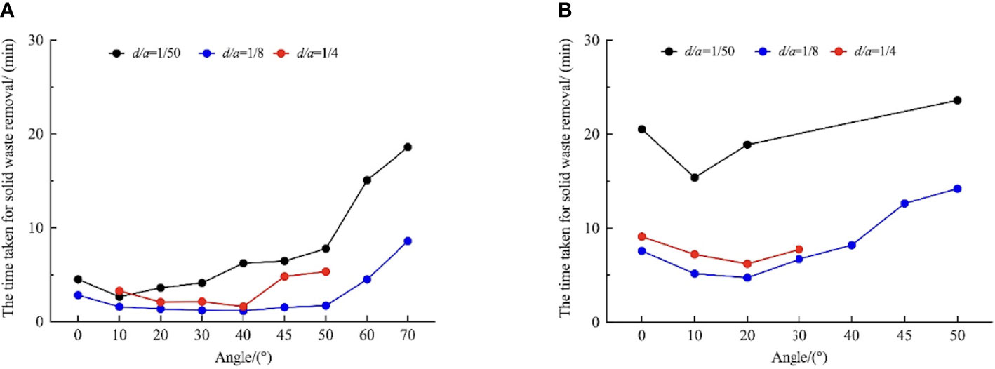
Figure 8 The time taken for solid waste removal under different conditions: (A) Single-inlet mode; (B) Dual-inlet mode.
Figure 9 shows the residual mass of solid waste in cases where the solid waste removal does not complete in 30 minutes. It should be reminded that this figure does not cover the cases in which the complete removal time is larger than 30 minutes. Figure 9A presents the mass of the residual solid waste in a tank with a single inlet. It is observed that when θ is set to 80°, the aquaculture tank existed residual solid waste by different degrees in each working condition. When d/a=1/4 and θ=80°, the residual mass of solid waste was higher than that at θ=0°, 70°, and 60°. Figure 9B shows the distribution of the residual mass of solid waste in the tank with dual inlets and a jetting angle of 60° to 80°. It is found that this configuration has low performance in solid waste removal.

Figure 9 Residual mass of solid waste under different conditions: (A) Single-inlet mode; (B) Dual-inlet mode.
Compared with other working conditions, the tank with a single inlet and a d/a of 1/8 has a relatively low solid waste removal time regardless of the jetting angle. When d/a is set to 1/50, not all of the solid waste is discharged from the tank within 30 minutes, but the residual mass of solid waste is minimum at d/a=1/4. In this section, the tank performance with a dual inlet system and four different jetting angles were analyzed. It was found that the lowest time of complete solid removal can be achieved for d/a=1/8. When θ was increased from 60° to 80°, the solid waste could not be completely discharged regardless of the jetting position. At a given flow rate in a single-inlet aquaculture tank, a reasonable solid waste removal efficiency can be achieved when d/a is set to 1/8 and the jetting angle θ increases from 30° to 40°.
Masaló and Oca (2016) showed that the removal of solid waste is closely related to the flow field and hydrodynamic characteristics of the aquaculture tank. In this regard, parameter DU50 was introduced as a powerful tool to evaluate different configurations in a RAS tank.
The results of the average velocity and uniformity coefficient of velocity distribution under different conditions are shown in Figures 10 and 11, respectively. It is observed that in a single-inlet tank with a d/a of 1/50, as the jetting angle θ increases from 10° to 80°, the average velocity vavg decreases, thereby decreasing DU50. When d/a=1/8, the highest vavg, and DU50 can be obtained at a jetting angle of 30° and 20°, respectively. When d/a=1/4, the highest vavg, and DU50 occur at θ=20°. Figures 10B and 11B show that in a dual-inlet tank with a d/a of 1/50, as the jetting angle increases, vavg decreases continuously, while DU50 decreases first and then increases. It is found that the maximum and minimum values of DU50 occur at jetting angles of 10° and 80°, respectively. When d/a=1/8, both vavg and DU50 decrease with the increase in the jetting angle, and the maximum values of vavg and DU50 occur at θ=20°. When d/a=1/4, the average velocity vavg increases first and then decreases with the increase in the jetting angle, and the maximum value occurs at θ=40°.
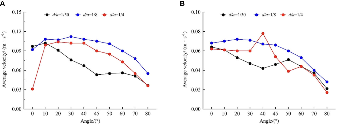
Figure 10 Distribution of the average velocity under different conditions: (A) Single-inlet mode; (B) Dual-inlet mode.

Figure 11 Distribution of the uniformity coefficient under different conditions: (A) Single-inlet mode; (B) Dual-inlet mode.
In a RAS tank, an effective solid waste collection strategy ensures clean and stable water quality. Meanwhile, the distribution of the flow velocity highly depends on solid waste removal efficiency. In this regard, the PIV technique was used and image processing was carried out on the MATLAB platform to visualize the measurements.
In the present study, sixty tests were carried out to analyze the flow field. Effects of the inlet layout in terms of the flow field on the horizontal bottom plane were explained using velocity contours. In order to analyze the tank performance in removing solid wastes, the flow field characteristics are discussed in this section. Figures 12 and 13 show the flow fields of the best and worst cases in a single-inlet and a dual-inlet tank, respectively. The long black arrow represents the jetting angle of inlet, the color denotes the information of velocity magnitudes, the blue represents the lower velocity zone, and the red represents the higher velocity zone.
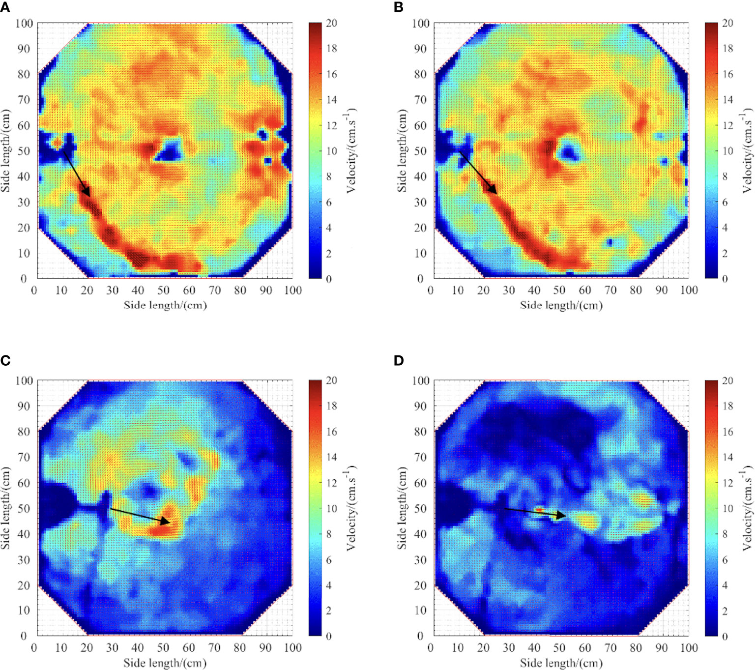
Figure 12 Flow field contours in a single-inlet aquaculture tank: (A) d/a=1/8; θ=30°; (B) d/a=1/8; θ=40°; (C) d/a=1/4; θ=70°; (D) d/a=1/4; θ=80°.
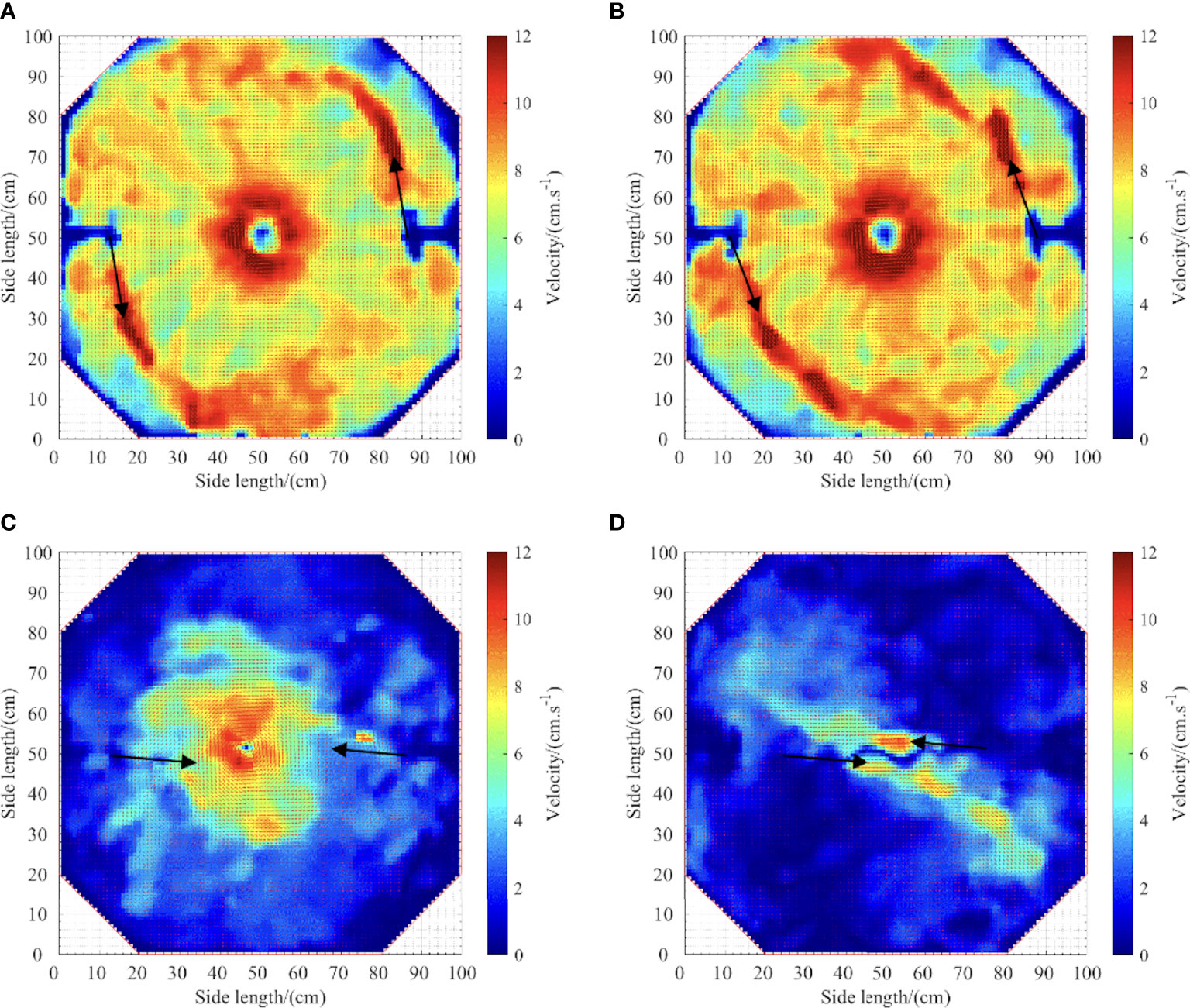
Figure 13 Flow field contours in a dual-inlet aquaculture tank: (A) d/a=1/8; θ=10°; (B) d/a=1/8; θ=20°; (C) d/a=1/8; θ=80°; (D) d/a=1/4; θ=80°.
Figures 12A, B show that a single-inlet tank with a d/a of 1/8 and a jetting angle of 30°-40° has a reasonable performance in removing solid wastes. It is observed that the solid waste removal efficiency with d/a=1/8 is higher than those with d/a=1/4 or 0. Accordingly, it is concluded that there is a high-intensity circulation near the outlet and only in a small zone of the low-velocity zone, which forms near the tank wall. Since high velocities in the central zone promote solid waste settling, this phenomenon has consequences on the self-cleaning features of the tank. When d/a =1/4, the solid waste removal efficiency is low for θ=70° and 80°. Figures 12C, D show that the jetting position and the center of the tank could be regarded as the radius of circular motion and there is a high-velocity region near the jetting where the water flow is driven by the vortex in the tank center. It is worth noting that the jetting position is a major contributor to the motion of the solid waste in the tank. The water flow makes a circular motion around the tank and the flow velocity gradually decreases from the tank center to the tank periphery. There is no circulation without a high-velocity zone around the tank.
Figures 13A, B show that in the dual-inlet tank with d/a=1/8, the highest solid waste removal efficiency, highest overall flow velocity, and good hydrodynamic characteristics can be achieved with jetting angles θ of 10° and 20°. The water flow rapidly contacts the tangent angle of the tank and brings sufficient orientation function, thereby forming a vortex in the center of the tank. Consequently, the energy loss caused by refraction and reflection reduces significantly. Obviously, the inlet angle is close to the center of the tank, and only a small circulation zone forms in the center of the tank, while Figures 13C, D reveal that there is a large zone of low-velocity flow around the tank wall at the jetting angle of 80°.
Reaching a uniform flow distribution is a great challenge in the design and operation of culture tanks to improve feed efficiency, achieve good mixing, and improve water quality (Gorle et al., 2018a). The average velocity of the flow is proportional to the uniformity coefficient of the velocity distribution in experiments caused by the circulation vortex. The performed analyses demonstrate that when the flow velocity reaches a certain value, a vortex would appear. The variation of vortex velocity is that the velocity diffuses and attenuates outward from the center, and the attenuation process is gradual, thus the evolution of the velocity in the tank is reflected in gradient descent. On the contrary, there is often no vortex and the kinetic energy tank is completely driven by the jetting port. Therefore, the energy attenuation is easier to occur and the velocity difference is more obvious. What’s more, rapid removal of residual uneaten feed and fish feces in tanks is necessary for adequate fish welfare and performance. Xue et al. (2022) used the CFD-assisted design to investigate the hydrodynamics and self-cleaning property. The results showed that hydrodynamics is the direct-acting factor in the self-cleaning property of the aquaculture tank system and the existing culture tank could be improved by adjusting the inlet pipe layout position appropriately.
The configuration of experimental setups was consistent with those reported in (Oca and Masaló, 2007; Oca and Masaló, 2013), in which the effect of the straight cut angle on the inlet flow rate was studied in the rectangular aquaculture tank with a length/width (L/W) ratio of 0.95. When d/a=1/50, the straight cut angle brings the diversion effect sufficiently. Moreover, the energy loss greatly increases by the friction between the water flow and the tank wall. In this case, the solid waste around the tank hardly approaches the center. When d/a=1/8, a closed triangular zone does not form anymore so there is no backflip around the hypotenuse wall. These results are consistent with those reported by Wu and Gao (2005) . Xue et al. (2020) showed that small-scale turbulence forms between the inlet port and the tank wall, and the inlet structure promotes the creation of local jets and vortices behind them, which will adversely affect the solid waste removal efficiency. When d/a=1/4, more low-velocity zones appear at jetting angles of 70° and 80°, and the solid waste removal efficiency is lower than that of other cases (Gorle et al., 2020).
With a constant flow supplied in a confined domain, the velocity gradient mainly appears near the tank center, where the flow velocity is much higher than that of experiments with a dual-inlet tank. These results are consistent with those reported by Labatut et al. (2007). In a single-inlet tank, Zhang et al. (2022) showed that there is an optimal solid waste removal efficiency in a tank with a jetting angle of 15°. Compared with experimental results, the calculated results have small deviations, which may be attributed to the difference in hydraulic retention times. Gorle et al. (2019) revealed that radial orientation of lower inlet nozzles in a dual-inlet tank improves the overall hydrodynamic performance of the tank. However, these investigations were mainly focused on the effect of single factors on the tank performance and did not consider the possible effect of turbulence generated by the interaction between the jetting position and the jetting angle. Significantly, Zhao et al. (2022) pointed out that flow velocity in culture tanks can be adjusted to provide much higher swimming speeds and thus effectively exercise fish. Therefore, the design of the velocity must meet the self-cleaning ability and speed requirements of the fish growth jointly in actual aquaculture engineering.
In the present study, the effect of the inlet layout on the solid waste removal efficiency of the octagonal RAS tank is analyzed. To this end, the flow pattern in an octagonal RAS tank was investigated using the PIV technique. It was found that the inlet layout has a considerable impact on the solid waste removal efficiency of the aquaculture tank. The main conclusions can be summarized as follows:
1. A single-inlet tank with a d/a ratio of 1/8 has higher solid waste removal efficiency than a similar tank with a d/a ratio of 1/4 or 1/50. When the jetting angle θ varies in the range of 10 ~ 40°, the tank has reasonable self-cleaning features, and optimal solid waste removal efficiency can be achieved with d/a=1/8 and θ =30°.
2. A dual-inlet tank with a d/a ratio of 1/8 has higher solid waste removal efficiency than a similar tank with a d/a ratio of 1/4 or 1/50. When d/a=1/8, the optimal solid waste removal efficiency can be achieved for θ=10° or 20°.
3. For a given flow rate and a large jetting angle, the water flow in a dual-inlet tank is easily affected by resistance, and the energy consumption increases, which is not conducive to the removal of solid waste. Accordingly, the single-inlet tank outperforms the dual-inlet tank from the aspect of velocity performance.
The original contributions presented in the study are included in the article/supplementary material. Further inquiries can be directed to the corresponding authors.
The ethics committee approval from the authors' institution have been obtained for this study.
JH: Data curation, Formal analysis, Writing-original draft; DF: Conceptualization, Funding acquisition, Resources, Writing-review & editing; XQ: Conceptualization, Funding acquisition, Resources, Supervision; HZ: Methodology, Software; LW: Conceptualization, Supervision; XZ: Investigation, Methodology; FG: Conceptualization, Funding acquisition, Resources. All authors contributed to the article and approved the submitted version.
This research was funded by the National Natural Science Foundation of China under grant number 31902425, the Natural Science Foundation of Zhejiang Province under grant number LGN21C190010, LGN19C190001 and the Bureau of Science and Technology of Zhoushan under grant number 2020C21003, 2021C31023.
The authors would like to thank all the reviewers who participated in the review, as well as MJEditor (https://www.mjeditor.com) for providing English editing services during the preparation of this manuscript.
The authors declare that the research was conducted in the absence of any commercial or financial relationships that could be construed as a potential conflict of interest.
All claims expressed in this article are solely those of the authors and do not necessarily represent those of their affiliated organizations, or those of the publisher, the editors and the reviewers. Any product that may be evaluated in this article, or claim that may be made by its manufacturer, is not guaranteed or endorsed by the publisher.
An C.-H., Sin M.-G., Kim M.-J., Jong I.-B., Song G.-J., Choe C. (2018). Effect of bottom drain positions on circular tank hydraulics: CFD simulations. Aquac. Eng. 83, 138–150. doi: 10.1016/j.aquaeng.2018.10.005
Benoit D. (2007). Hydrodynamic chanracteristics of muti-drain circular tanks. [dissertation/master's thesis]. [Canada (NB)]: University of New Brunswick.
Dauda A. B., Ajadi A., Tola-Fabunmi A. S., Akinwole A. O. (2019). Waste production in aquaculture: Sources, components and managements in different culture systems. Aquac. Fish. 4, 81–88. doi: 10.1016/j.aaf.2018.10.002
Davidson J., Summerfelt S. T. (2004). Solids flushing, mixing, and water velocity profiles within large (10 and 150 m3) circular’ Cornell-type’ dual-drain tanks. Aquac. Eng. 32 (1), 245–271. doi: 10.1016/j.aquaeng.2004.03.009
Duarte S., Reig L., Masalo I., Blanco M., Oca J. (2011). Influence of tank geometry and flow pattern in fish distribution. Aquacult. Eng. 44 (2), 48–54. doi: 10.1016/j.aquaeng.2010.12.002
Du Y., Chen F., Zhou L., Qiu T., Sun J. (2020). Effects of different layouts of fine-pore aeration tubes on sewage collection and aeration in rectangular water tanks. Aquac. Eng. 89, 102060. doi: 10.1016/j.aquaeng.2020.102060
Fisheries and Fishery Administration Bureau of the Ministry of Agriculture and Rural Zones. National Aquatic Technology Promotion Center, China Fisheries Association. China Fishery Statistical Yearbook. (Beijing: China Agriculture Press) (2022) pp. 17. (China Fishery Statistical Yearbook)
Gorle J., Terjesen B., Summerfelt S. (2020). Influence of inlet and outlet placement on the hydrodynamics of culture tanks for Atlantic salmon. Int. J. Mech. Sci. 188, 105944. doi: 10.1016/j.ijmecsci.2020.105944
Gorle J. M. R., Terjesen B. F., Mota V. C., Summerfelt S. (2018b). Water velocity in commercial RAS culture tanks for Atlantic salmon smolt production. Aquac. Eng. 81, 89–100. doi: 10.1016/j.aquaeng.2018.03.001
Gorle J. M. R., Terjesen B. F., Summerfelt S. T. (2018a). Hydrodynamics of octagonal culture tanks with Cornell-type dual-drain system. Comput. Electron. Agric. 151, 354–364. doi: 10.1016/j.compag.2018.06.012
Gorle J. M. R., Terjesen B. F., Summerfelt S. T. (2019). Hydrodynamics of Atlantic salmon culture tank: Effect of inlet nozzle angle on the velocity field. Comput. Electron. Agric. 158, 79–91. doi: 10.1016/j.compag.2019.01.046
Labatut R. A., Ebeling J. M., Bhaskaran R., Timmons M. B. (2007). Effects of inlet and outlet flow characteristics on mixed-cell raceway (MCR) hydrodynamics. Aquac. Eng. 37 (2), 158–170. doi: 10.1016/j.aquaeng.2007.04.002
Masaló I., Oca J. (2014). Hydrodynamics in a multivortex aquaculture tank: Effect of baffles and water inlet characteristics. Aquac. Eng. 58, 69–76. doi: 10.1016/j.aquaeng.2013.11.001
Masaló I., Oca J. (2016). Influence of fish swimming on the flow pattern of circular tanks. Aquac. Eng. 74, 84–95. doi: 10.1016/j.aquaeng.2016.07.001
Masaló I., Oca J. (2010). Distribution of velocities in aquaculture circular tanks with rotating flow and evaluation of uniformity. a: Aquaculture Europe 2010. seafarming tomorrow. Eur. Aquaculture Soc. 914–915.
Masaló I., Oca J. (2007). Design criteria for rotating flow cells in rectangular aquaculture tanks. Aquac. Eng. 36 (1), 36–44. doi: 10.1016/j.aquaeng.2006.06.001
Masaló I., Oca J. (2013). Flow pattern in aquaculture circular tanks: influence of flow rate, water depth, and water inlet and outlet features. Aquac. Eng. 52, 65–72. doi: 10.1016/j.aquaeng.2012.09.002
Patterson R. N., Watts K. C., Timmons M. B. (1999). The power law in particle size analysis for aquacultural facilities. Aquac. Eng. 19 (4), 259–273. doi: 10.1016/S0144-8609(98)00054-5
Ren X. Z., Xue B. R., Jiang H. Z., Yu L. P., Tiao. J., Ma. Z., et al. (2021). Numerical study on the influence of double-inlet pipes system for single-drain rectangular arc angle aquaculture tank on hydrodynamic characteristics. Mar. Environ. Sci. 40 (01), 50–56. doi: 10.13634/j.cnki.mes.2021.01.007
Robinson S. K. (1991). Coherent motions in the turbulent boundary layer. Annu. Rev. Fulid Mech. 23, 601–639. doi: 10.1146/annurev.fl.23.010191.003125
Sin M., An C., Cha S., Kim M., Kim H. (2021). A method for minimizing the zone of low water flow velocity in a bottom center drain circular aquaculture tank. J. World Aquac. Soc 52. 1221–1233. doi: 10.1111/jwas.12792
Summerfelt S. T., Mathisen F., Holan A. B., Terjesen B. F. (2016). Survey of large circular and octagonal tanks operated at Norwegian commercial smolt and post-smolt sites. Aquac. Eng. 74, 105–110. doi: 10.1016/j.aquaeng.2016.07.004
Timmons M. B., Summerfelt S. T., Vinci B. J. (1998). Review of circular tank technology and management. Aquac. Eng. 18, 51–69. doi: 10.1016/S0144-8609(98)00023-5
Venegaset P. A., Narváez A. L., Arriagada A. E., Llancaleo K. A. (2014). Hydrodynamic effects of use of eductors (Jet-mixing eductor) for water inlet on circular tank fish culture. Aquac. Eng. 59, 13–22. doi: 10.1016/j.aquaeng.2013.12.001
Wang Z. B. (2019). Study on particle motion characteristics of liquid injected gas-solid fluidized bed based on PIV (Changchun: Northeast Electric Power University).
Wu G. L., Gao S. L. (2005). Flow characteristics and resistance of circum fluence in rectangle shrimp pond. J. Zhanjiang Ocean Univ. 1), 64–68.
Xue B. R., Jiang H. Z., Ren X. Z., Yu L. P., Zhang Q., Wang G. F. (2020). Study on the influence of the relative inflow distance on the flow field characteristics in square arc angle aquaculture tank. Fishery Modernization 47 (04), 20–27. doi: 10.3969/j.issn.1007-9580.2020.04.004
Xue B. R., Yu L. P., Zhang Q., Ren X. Z., Bi C. W. (2021). A numerical study of relative inflow distance on the influence of hydrodynamic characteristics in the single-drain rectangular aquaculture tank with arc angles. J. Fisheries China 45 (3), 444–452. doi: 10.11964/jfc.20191112077
Xue B. R., Zhao Y. P., Bi C. W., Cheng Y., Ren X. Z., Liu Y. (2022). Investigation of flow field and pollutant particle distribution in the aquaculture tank for fish farming based on computational fluid dynamics. Comput. Electron. Agric. 200, 107243. doi: 10.1016/j.compag.2022.107243
Zhang X. S., Fu L. L., Lv Z. M. (2017). Research development review of recirculation aquaculture mode in China and abroad. Feed Industry 38 (6), 61–64. doi: 10.13302/j.cnki.fi.2017.06.013.
Zhang Q., Gui J. S., Xue B. R., Ren X. Z., Xiong Y. Y., Wang G. F. (2022). Study on the effect of dual-drain system on flow field characteristics in rectangular arc angle aquaculture tank. Fishery Modernization 47 (06), 19–25. doi: 10.3969/j.issn.1007-9580.2020.06.004
Zhao Y. P., Xue B. R., Bi C. W., Ren X. Z., Liu Y. (2022) Influence mechanisms of macro-infrastructure on micro-environments in the recirculating aquaculture system and biofloc technology system Rev. Aquac. 1–19 doi: 10.1111/raq.12713
Keywords: RAS, inlet layout, solid waste removal efficiency, flow field, octagonal aquaculture tank
Citation: Hu J, Zhang H, Wu L, Zhu F, Zhang X, Gui F, Qu X and Feng D (2022) Investigation of the inlet layout effect on the solid waste removal in an octagonal aquaculture tank. Front. Mar. Sci. 9:1035794. doi: 10.3389/fmars.2022.1035794
Received: 03 September 2022; Accepted: 19 October 2022;
Published: 07 November 2022.
Edited by:
Ce Shi, Ningbo University, ChinaReviewed by:
Zhao Yunpeng, Dalian University of Technology, ChinaCopyright © 2022 Hu, Zhang, Wu, Zhu, Zhang, Gui, Qu and Feng. This is an open-access article distributed under the terms of the Creative Commons Attribution License (CC BY). The use, distribution or reproduction in other forums is permitted, provided the original author(s) and the copyright owner(s) are credited and that the original publication in this journal is cited, in accordance with accepted academic practice. No use, distribution or reproduction is permitted which does not comply with these terms.
*Correspondence: Xiaoyu Qu, cXV4aWFveXVAempvdS5lZHUuY24=; Dejun Feng, ZmVuZ2RqQHpqb3UuZWR1LmNu
Disclaimer: All claims expressed in this article are solely those of the authors and do not necessarily represent those of their affiliated organizations, or those of the publisher, the editors and the reviewers. Any product that may be evaluated in this article or claim that may be made by its manufacturer is not guaranteed or endorsed by the publisher.
Research integrity at Frontiers
Learn more about the work of our research integrity team to safeguard the quality of each article we publish.