 Shaowei Zhang
 Chuan Tian
 Fenghua Zhou
- 1Institute of Deep-Sea Science and Engineering, Chinese Academy of Sciences (CAS), Hainan, China
- 2South China Sea Institute of Oceanology, Chinese Academy of Sciences (CAS), Guangzhou, China
We designed a hybrid system named Mooring Buoys Observation System with Benthic Electro-optical-mechanical Cable (MBOSBC) for long-term seafloor and sea surface multi-parameter ocean observation. The electro-optical-mechanical (EOM) cable connects a sea surface buoy and a seafloor junction box so as to establish a transmission link of information and power between the sea surface and the seafloor. The EOM cable also plays the role of mooring tether to the MBOSBC and has to withstand the rigorous marine environment—experiencing mooring loads under complex marine environmental conditions for long periods of time. The data transmission of the system includes the EOM, satellite communication, wireless radio, and acoustic communication. The system power is generated by a wind turbine and solar panels and is transmitted to the seafloor junction box. An acoustic communication instrument is used to gather the sample data from other benthic nodes, such as seafloor landers, AUVs, and underwater gliders. MBOSBC is designed to operate from shallow water to deep sea, and to simultaneously monitor sea surface hydrology, meteorology, and water quality, as well as benthic temperature, pressure, salinity, currents, and seafloor video. We provide the MBOSBC architecture design, including the mechanical design, control, power, data transmission, and EOM cable. Finally, we describe the launch and recovery process of MBOSBC, as well as experimental results.
Introduction
Seafloor observatories provide a method to understand physical, chemical, and geological seafloor processes. Seafloor observatories can monitor the environment as well, including ocean climate predictions, ocean upwelling, eddies, seismicity, geomagnetic variation, temperature, salinity, currents, and gas occurrence over long periods, offering many multidisciplinary ocean data for scientists in real time. The NEPTUNE Canada project in Ref (Delaney et al., 2000). is the most representative example of state-of-the-art marine technology. Also, seafloor observatories have potential applications in the offshore operations of the oil and gas industry. Finally, seafloor observatories are utilized for supporting maritime security; specifically, seafloor observatories with seafloor hydrophone arrays can track and identify surface vessels, AUVs, and cetaceans.
Cabled seafloor observatories have been developed in Canada, USA, and Japan. This kind of system transmits power to an underwater junction box through an EOM cable from the shore station. By using the EOM cable and junction box, cabled seafloor observatories establish a connection to shore stations, benthic nodes, and sensors. However, the EOM cable, launching the system, and maintaining the system involve huge costs. Also, it is difficult to change or adjust the position of the seafloor junction box once the system is completely launched. Therefore, cabled seafloor observatory systems are difficult to move. These properties limit the application of surface and seafloor observation for areas far from the shore. In addition, seafloor observatories are difficult to relocate in response to emergencies events.
Moored buoy seafloor observatories offer a strategy to cope with these challenges, which combine renewable energy, an EOM cable, and satellite communication to establish power and communication transmission links, so as to construct a system that can provide real-time synchronized three-dimensional observations of the sea surface and the seafloor. Renewable energy, such as from wind turbines and solar panels, makes it possible to offer renewable power for the seafloor observatories. The EOM cable offers power and data transmission capability between the seafloor and the sea surface. Moored buoy seafloor observatories provide a supplementary observation method for cabled seafloor observatories; they are a reusable and portable system because they can be recovered and relocated as required once deployed. This kind of system is suitable for ocean area, whereas a shore station is difficult to establish or may be undesirable. Finally, this kind of transferable-fixed regional ocean observatory system is suitable for emergencies events, especially for maritime security using seafloor hydrophone arrays from surrounding offshore islands. Ocean buoys mainly collect the data, which include the temperature, salinity, ocean current, waves, and oceanographic meteorology. Buoys provide support for ocean climate prediction and research on physical ocean processes, and seafloor nodes are used for geophysical and environmental monitoring.
The MBARI Ocean Observatory System (MOOS) prototype in Refs (Chaffey et al., 2001; Chaffey et al., 2005; Hamilton and Chaffey, 2005). use an EOM cable to deliver power and communication to seafloor instruments, and it can be deployed in the deep ocean at depths reaching 4000 m. The system includes a 2.3-m-diameter buoy, an ocean benthic platform, and an EOM cable. The surface buoy collects as much as 40 W of solar and wind energy. The EOM cable connects the buoy and the ocean benthic instrument, so as to establish the power and data link between surface and seafloor. The EOM cable and the seafloor junction box are connected by ROV with a wet-mate electro-optical connector.
The Cabled Underwater Module for Acquisition of Seismological data (CUMAS) in Refs (Iannaccone et al., 2009; Martino et al., 2014). is designed to extend the land surveillance network toward the wide marine sector of the caldera system. CUMAS is the first marine network that integrates volcanic monitoring with the coastal observation system. The buoy has a weight of 17T, and the total weight of the seafloor module is 430 kg. The EOM cable that connects the buoy and the seafloor node has a diameter of 23 mm. The buoy is moored by another anchor chain at a depth of 97 m. The system was launched in the Campi Flegrei caldera (southern Italy), one of the most hazardous and populated volcanic areas in the world; it is generally undesirable to set up a shore station in these areas. The scientific sensor includes a seismometer and a hydrophone, and it can detect current and water temperature. Signal transmission occurs through the network protocol and the RS485 protocol through the cable, and the power supply on the cable is 48 VDC.
CSnet’s Offshore Communications Backbone (OCB) in Refs (Clark et al., 2009; Georgiou et al., 2010; Clark and Kocak, 2011). is a hybrid buoy/cabled observatory. The CSnet consists of a buoy, a buoy riser cable (mooring/power and communications), an anchor, a seafloor cable, and four seafloor nodes. The Cyprus-TWERC (Tsunami Warning and Early Response system of Cyprus) initially served as the CSnet prototype system for the Tsunami Warning and Early Response system of Cyprus and was first deployed at a depth of 2400 m in 2010. The buoy provides 5 kW of power for the seafloor node and communication at 3 Mbps via a satellite link. CSnet was selected to measure seafloor pressure to analyze the onshore destruction caused by seismically generated tsunamis. The Cyprus-TWERC project developed the framework to forecast marine disasters.
The OOI (Ocean Observatories Initiative) Coastal Surface Mooring Buoy System, which is maintained as part of the Regional Cable Array, is introduced in Refs (Smith et al., 2018; Trowbridge et al., 2019). The maximum launching depth is 450 m. The Coastal Surface Mooring Buoy System includes a surface buoy with a 3-m-tall tower, a near-surface instrument frame located at a depth of 7 m, and a multifunction node at the sea bottom. These three components are connected by the EOM cable for information and power transmission between the sea bottom and the sea surface. Due to the Coastal Surface Mooring Buoy System, the buoy has to offer enough buoyancy for the moored armored metal cable. Therefore, at present, this kind of system is rarely applied in deep waters.
Satellite communication offers a low-bandwidth path for the buoys, whereas optical fiber communication provides a high-bandwidth path from the seafloor to the sea surface through the EOM cable. Currently, the transmission rate of the iridium (9522 modular) used in a traditional buoy is 2.4kbps, which is mainly used for the transmission of instrument observation data. The surface buoy of CSnet is equipped with a VSAT modular, so that it can offer a data bandwidth in excess of 2 Mbps and transmit the data through the C-Band satellite, as shown in Ref (Sekino and Clark, 2003).
The cable used in MOOS is net-buoyant, as shown in Refs (Han and Grosenbaugh, 2006; Grosenbaugh et al., 2006). which is different from the seafloor observation network. The traditional EOM cable used in the seafloor network is a steel wire armored EOM cable, lying statically on the seafloor. This kind of EOM cable is a steel wire armored cable. Steel wire armored EOM cables are utilized in near-shore areas with shallow depths, but they are not suitable for deep-sea buoy mooring. Because the net buoyancy of the buoy is limited, the EOM cable has have sufficient net buoyancy to hang in the water for long term, or else many floats may be needed to balance the weight of the cable. Vectran-fiber, nylon, and polyester are selected as strengthening materials. This kind of net-buoyancy EOM cable requires high strength, excellent bending properties, watertight performance, and wear resistance. The properties of EOM cables with different strength materials are compared in Ref (Mellinger et al., 2003). especially the static and dynamic responses of the mooring EOM cable.
Tethering technology is used in Shallow Ocean, as shown in Refs (Iannaccone et al., 2009; Makris et al., 2014). where the anchoring rope and coaxial cable are roped together as the mooring component, so the coaxial cable does not need experience the moored force. The analog signals transmit on the coaxial cable, which is converted to a digital signal by an A/D converter at the buoy and seafloor. This kind of mooring method is difficult to utilize in deep sea because it is hard to launch and recover the system while the anchor chain and cable are entangled together.
In this paper, we design the Mooring Buoys Observation System for Benthic with Electro-optical-mechanical Cable (MBOSBC) for seafloor and sea surface observation of the South China Sea for ocean meteorology, ocean physical processes, and water quality. MBOSBC includes a mooring buoy and a benthic observation node, and these two components are connected by an EOM cable. The mooring buoy plays the role of observation and relay platform for power generation and data transmission. The benthic observation node is designed for monitoring ocean physical processes and seafloor image acquisition, as well as anchoring the mooring buoy. We established the cable and the acoustic communication linked between the mooring buoy, the seafloor moored node, and an independent node. The acoustic communication is used to collect seafloor sample information from other seafloor observation nodes, such as glider and seafloor lander. MBOSBC can be relocated or deployed rapidly for transient observation or long-term observation. Especially, the sea surface buoy, as the power generator and data transmitter, has a mixture of capabilities for long-term observation and real-time data transmission for ocean observation. This paper gives a description of the architecture, function, design, and experiments of the system, which is organized as follows. First, we give the concept design of the MBOSBC system. Second, we give a detailed description of the mooring buoys and the benthic observation node. Third, we introduce the EOM cable and mooring technology. Fourth, we provide experimental results, including the launch and recovery processes. Finally, we conclude the paper and discuss future works.
System design
MBOSBC is aimed to work with the coastal observatories of the South China Sea, as shown in Figure 1. Using the surface buoy and seabed observation system with an EOM cable, we provide an open test platform to verify the reliability of various communication modes, renewable energy, and integration of data acquisition/transmission technology. Through this research, we hope to provide technical reference for buoy modular integration, underwater networking technology, and industrial application of this system, especially for the solution of real-time transmission technology of isolated observation nodes with an EOM cable.
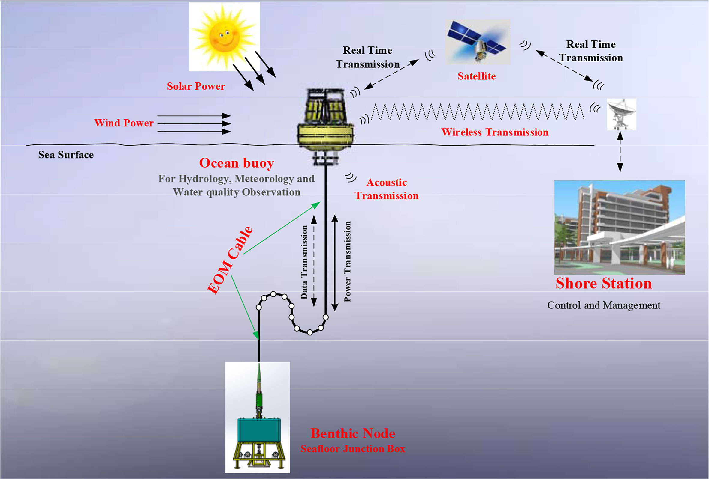
Figure 1 Concept design of Mooring Buoys Observation System for Benthic with Electro-Optical-Mechanical Cable (MBOSBC).
MBOSBC integrates seafloor and sea-surface instruments for a broad spectrum of environmental, meteorological, and hydrological observatory data, including water temperature, pressure, salinity, current, wind speed/direction, air temperature, relative humidity, barometric pressure, and water chemistry. We integrate a seafloor video module, including a light, camera, and a PTZ, to verify the power capacity of MBOSBC and its wireless radio transmission. In the future, MBOSBC will be equipped with a geomagnetic sensor, a hydrophone, and a seismometer for extreme environmental monitoring.
MBOSBC communication integrates an optical fiber, acoustic, Ethernet network, wireless radio, and satellite as a communication network system of regional ocean observatories. MBOSBC obtains its seafloor data from the EOM cable and collects seafloor lander/glider data with acoustic communication. MBOSBC transmits the data in real time or near-real-time to the shore control center to construct a closed loop of the “ocean observatories data stream.”
The overall system architecture is shown in Figure 2, including three modules: the mooring buoy, the benthic node, and the EOM cable. The mooring buoys play the role of sea surface observation, data communication, and energy supply. The benthic node contains the junction box, the oceanographic instruments, the seafloor video module, and the buoy anchor block. The junction box contains three modules for power management, control and data acquisition, and seafloor junction box status monitoring. Detailed information is given in the following sections.
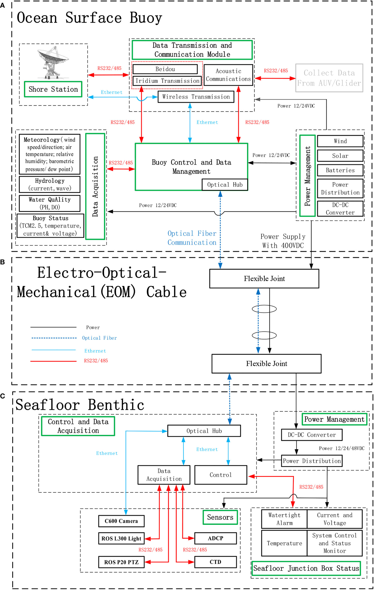
Figure 2 Detailed architecture of MBOSBC: (A) mooring buoy; (B) seafloor junction box; (C) EOM cable for mooring and power and data transmission.
The control and data management module integrates the power module, the communications module, the sample instruments of the buoys and benthic observation node, and EOM cable, as shown in Figure 2. We monitor the voltage and current of the battery, the wind turbine, and the solar panel in real time. With this information, we adjust the acquisition frequency of the instruments to optimize the energy consumption.
The embedded computer and the DC/DC converter connect the mooring buoys and the benthic observation node. Data are transmitted between the mooring buoys and the benthic observation node through the EOM cable and the optical Ethernet hub. The embedded computer on the mooring buoy integrates the heterogeneous data stream of the mooring buoys and the benthic observation node. Data are stored on the buoy as a redundant backup module, which includes an SD card and a 2-T data recording disk. The data recording disk mainly stores the sea surface mini camera images and seafloor videos, and other sample data are stored on the SD card.
The control and data management module is the control core of the system, integrating the embedded computer, data acquisition and storage, power supply, communication. Therefore, it requires excellent stability and scalability, and we design this module with the following guidelines:
1. Realize data storage, exchange, and transmission.
2. Manage various kinds of sensors for data sampling, recording, packing, and uploading.
3. Adjustable sampling frequency.
4. Convenient for maintenance and expansibility. The hardware should have excellent expansion capability, including storage capacity and interface expansion, and the software should be easily maintained and upgraded.
Observation platform design
Mooring buoys
The mooring buoy has a rigid structure and is made of 304 steel. The main diameter of the buoy is 3 m, and the bottom diameter of the buoy is 1.5 m, as shown in Figure 3A. The displacement of the buoy is 4.2 Tons. The buoy body is divided into two parts: a watertight tank in the center, and four buoyancy cabins, which are arranged around the watertight tank. The electronic instruments are held in the watertight tank.
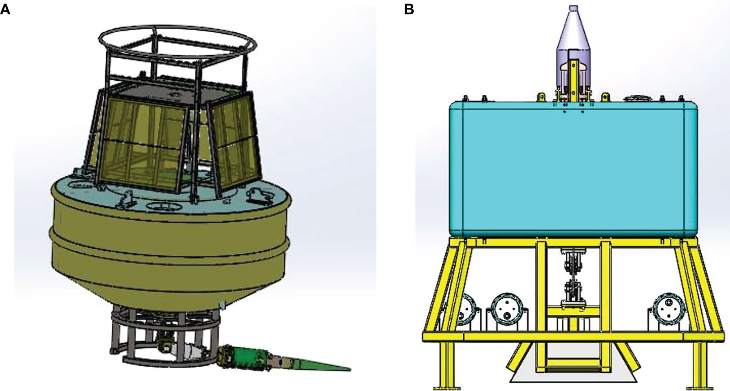
Figure 3 Mechanical design of buoy and benthic observation node. (A) Buoy (B) Benthic observation node.
The buoy is equipped with 24 rechargeable batteries (2 V, 500 Ah each). The power supply includes eight solar panels and a wind turbine. Each solar panel is nominally 100 W with dimensions of 1200 mm × 540 mm, and the wind turbine is nominally 150 W.
The mooring buoy is used for the observation of meteorological, hydrological, and water-quality data. Detailed information about the scientific sensors and status sensors is given in Table 1. The sampling frequency is set to satisfy the needs of marine science research. Specifically, we put a miniature camera on the buoy instrument frame for near-shore monitoring and verification of the wireless radio communication.
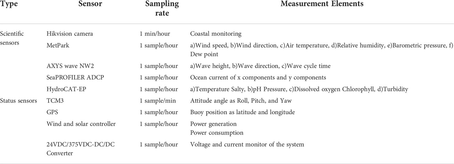
Table 1 Scientific and status sensors on the mooring buoy.
The status sensors provide information on the state of the buoy. TCM3 and GPS devices embedded with iridium provide the attitude and position of the buoy. The total power generation and daily power consumption are determined by the wind and solar controller and DC/DC converter, respectively.
Benthic observation node
For the benthic observation node, the junction box includes a titanium cylinder for power supply, and another titanium cylinder for data communication and control. The weight of the junction box is approximately 150 kg, which is surrounded by a cage with a weight of 1 ton. The cage has a length, width, and height of 2.25 m, 2.25 m, and 2.53 m respectively, as shown in Figure 3B. The seafloor junction box and the video module are fixed on the grid of the cage. The titanium cylinder of the junction box has a diameter of 320 mm and a length of 1060 mm. The DC/DC converter and data sampling and transmission module are fixed in the two titanium cylinders separately. The benthic observation node also plays the role of a seafloor anchor. The cage weighs 1 ton and contains the scientific instruments. The anchor block at the bottom center of the cage is 3 tons, so as to offer enough weight to moor the buoy. The anchor block can be released by the acoustic releaser when we recover the MBOSBC.
The junction box converts the 375 VDC from the EOM cable to 12 VDC, 24 VDC, and 48 VDC for the seafloor instruments. The junction box accepts input control commands via RS232, RS422, and RS485. The junction box offers 8-pin watertight connectors (SubConn MCBH8F) for the sensors for power supply and data transition. Ethernet communication connects the optical fiber from the EOM cable and the ARM embedded system with the TCP/IP protocols. The ARM embedded system facilitates data acquisition from the instruments and data transmission to the Ethernet.
The junction box hosts several instruments, including a seafloor video imaging system, a CTD, and an ADCP. Detailed information about the instruments is given in Table 2. The video module includes a C600 ROS camera, two L300 led lights, and a P20 Pan and Tilt Positioner. The video format of the C600 HD camera is 1080i/720p, and the coaxial signal output from the C600HD camera is transformed to TCP/IP protocols by a video server; thus, video protocols are able to be transmitted to the sea surface buoys with the EOM cable. The Ethernet (10/100 Mbps) is used to transform the video data. Finally, the seafloor video is transmitted to the shore station via wireless communication. Considering the limitation of the power supply, we set the camera and light to start and stop regularly, or they are intermittently turned on via wireless radio control from the shore station.
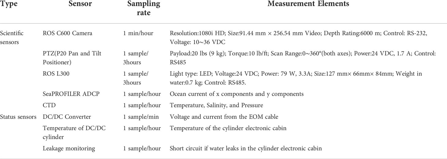
Table 2 Scientific and status sensors for the benthic observation node.
Communications module
The communication module is equipped with satellite communication, wireless radio communication ST5801GB-M1, and Evologics S2C acoustic communication, as shown in Figure 4. We establish the communication between the buoy and the benthic observation node with the optical fiber and Ethernet of the EOM cable. Detailed information about the communication instruments are given in Table 3.

Figure 4 Concept design of communications module.
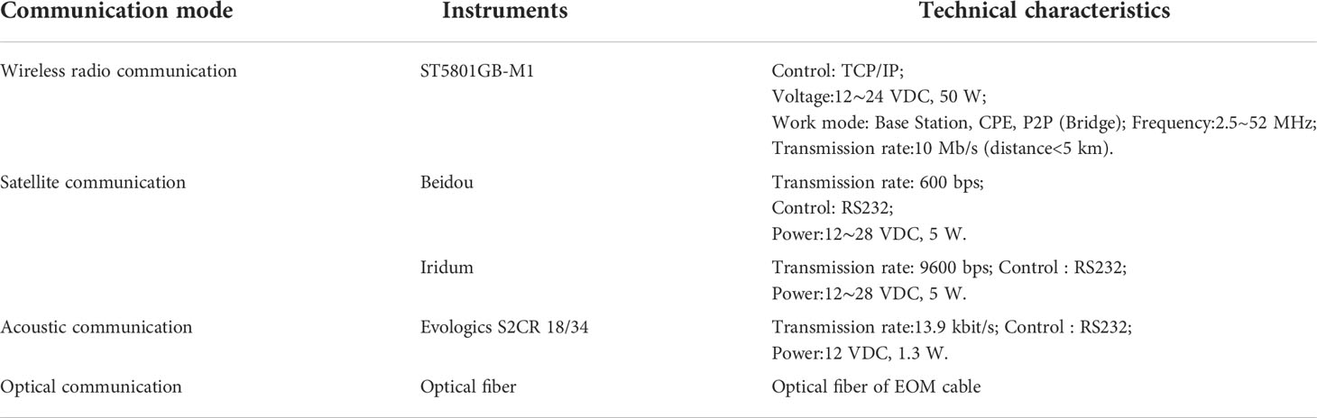
Table 3 Types and technical characteristics of communication module.
The Evologics S2C device is utilized to collect sample data from the AUV, lander, and other seafloor observational platforms. Wireless radio communication is used to transmit the videos to the shore station when we launch the MBOSBC near the coast. The nameplate power supply of wireless radio ST5801GB-M1 is 50 W/24 VDC, and the data transmission rate is 10 Mb/s within 5 km. The communication link for the seafloor video module to the buoy is established as “coaxial signal (C600 HD)-Ethernet (underwater junction box)-Ethernet/Optical Switch-EOM cable-Optical/Ethernet Switch-Ethernet(buoy)-wireless radio communication(buoy).” Satellite communication, including Beidou and Iridium, is utilized to transmit all data except the video data. When the MBOSBC is launched far from the coast, we find it difficult to transmit the video data. As a result, we select HIKVISION DS-7104HGH- F1/N as the video serve, shortened the recording time of the camera, and then store the video data in the server. The power consumption is 8W with 12VDC and weight less than 0.8kg. Details of the video serve design idea is shown in Figure 2.
We tested the transmission rate of the ST5801GB-M1 wireless radios that are located in our institute and boat, separately. We then moved the boat away from the coast gradually. The transmission distance varied from 1 km to 5 km. Detail information is shown in Ref (Zhang et al., 2018). When the distance was less than 1 km, the wireless transmission signal was strong and stable, with a transmission rate of 50 Mb/s. When the distance was from 1 km to 2.5 km, the transmission was unstable because of the mismatched settings of the wireless transceiver mode. At distances of 2.5 km to 3 km, we changed the transceiver mode, and as the distance increased, the transmission rate dropped sharply, as the wireless signal strength became weak. At distances of 3 km to 4 km, we increased the power supply (>24 W), and the transmission rate increased to 30 Mb/s. At distances of 4 km to 5 km, the transmission rate remained stable at 30 Mb/s at a supplied power of 24 W.
Power module
The power module is designed to collect and store wind and solar energy and then distribute the energy to the seafloor and sea surface instruments; it also transmits power to the seafloor via a standardized 375 VDC power bus. The overall system is described in Figure 5. The power module includes the solar panels, the wind turbine, and the battery blocks. We chose 24 blocks of 2-V 500-Ah AGM lead-acid batteries. As a result, the batteries offer a nameplate capacity of 1000 Ah with 24 VDC.
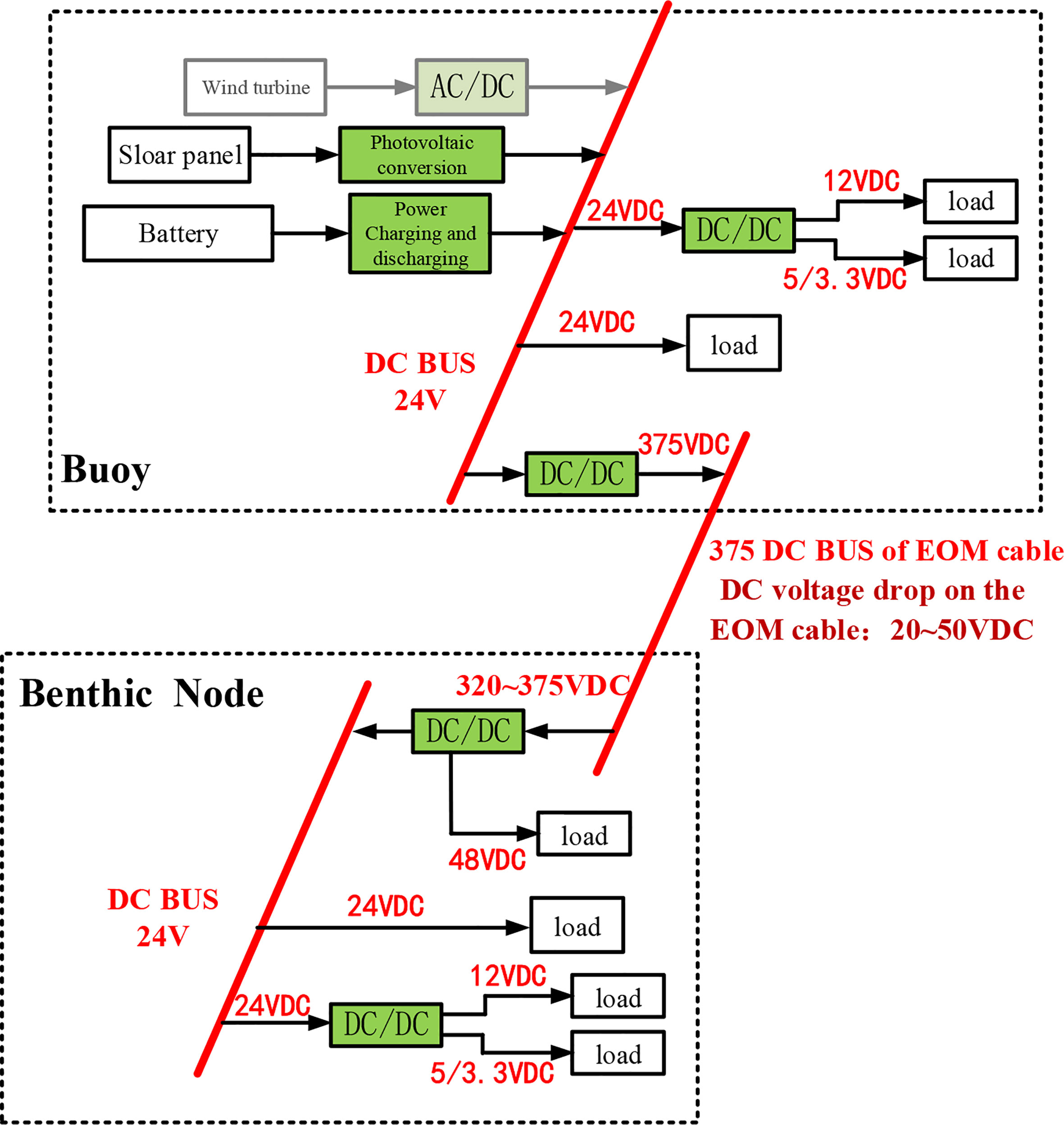
Figure 5 Power supply of MBOSBC.
Through the DC/DC converter, the sea surface instruments are powered by a 12 VDC bus, and the seafloor load is powered by a 375 VDC bus. For energy management and control, we give priority to ensure that power is supplied to the critical load, which mainly includes the communication instruments. Energy is then distributed to the observation instruments. When the system is located more than 10-km away from the coast, it is impossible control the camera through the wireless radio, so we have to start the seafloor video and the wireless radio in a preset intermittent mode.
The above-mentioned mode greatly reduces the energy consumption of the system. The sea surface observation costs 2.41 Ah at 12 VDC per day, whereas the seafloor observation costs 23.6Ah at 12 VDC per day. The buoy communications module costs 23.4 Ah at 12 VDC per day. The total energy consumption per day reaches 592.9 Wh. The actual instantaneous power consumption is 24.7 W. The photoelectric conversion efficiency of the solar panels reaches 10%, so the solar panels provide approximately 80 W of power for the system, which offer enough power for MBOSBC.
Ocean mooring technology with EOM cable
EOM cable
Two kinds of cables are utilized in the buoy mooring as are swon in Figure 6. First, we select Rochester Engineered Cable NO.A302351, with three optical fibers and three 11# AWG wires, as shown in Figure 6A. Two optical fibers are utilized for data transmission, and two copper wires are utilized for power transmission. The diameter of the EOM cable is 17.30 mm. The breaking strength of the EOM cable is 204.6 kN, and its weight in the water is 905 kg/km. The voltage rating @ 123 volts/mil is 2800 VDC, and the insulation resistance is 3000 MΩ·km. The cable is armored with three layers of steel wires. At the benthic node, the optical core and the electric core are separated and connected to the junction box through a watertight connector. A load bearing is designed and vulcanized with the EOM cable and the watertight connector, which is fixed on the buoy and seafloor node, and the mooring force of the buoy is transferred to the EOM cable through the load-bearing. We used this cable for initial experiments and testing. Because it is finished product, and it is worth considering for it relatively low-cost option.
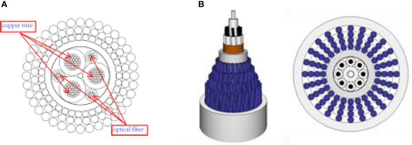
Figure 6 Section view of steel-wire armored EOM cable and vectran-fiber EOM cable. (A) Rochester Engineered Cable NO.A302351. (B) Vectran fibers cable.
We select the vectran-fiber cable in the later stage to try the application of the neutral buoyancy cable in the system. The weight of metal cable is large, the buoy should offer reserve buoyancy for different depth. At the same time, if we select the metal cable, it makes the system recovery complex. We have to lift the metal cable with hydraulic winch. If we select the vectran-fiber cable, and when we release the anchor block, the benthic node and the neutral buoyancy cable can automatically rise to the surface. We designed a net-buoyant EOM cable to replace the mooring armored cable. The EOM cable is utilized as the single-point mooring for MBOSBC. The EOM cable is composed of four optical fibers and eight 18# AWG wires. Two optical fibers are used for data transmission, and eight copper wires are used for power transmission. The diameter of the EOM cable is 30 mm, its breaking strength is 200 kN, and its weight in the water is 0~2.0 N/m. We did tensile tests on the EOM cable to verify its strength, so as to making sure that it can moor the buoy. We first tested the EOM cable with a nominal safe working load of 7 tons for approximately one hour, and then we tested the EOM cable with a minimum breaking load of 20 tons for approximately 10 minutes. The test results showed that the EOM cable could withstand the working load and the minimum breaking load. Detailed information about the testing is given in Ref (Yu et al., 2020). The weight of this kind of cable is relatively light, and the buoy is not required to provide additional reserve buoyancy. Compared with metal armored cable, vectran-fiber cable provides a good choice for the system launch and recovery in deep water.
In Ref (Yu et al., 2020), we establish the buoy mooring model and give the simulation result. The total mooring force of the buoy bottom is 32.6kN. And the safety factor is selected as 6, so the expected loads of the EOM cable is 200kN.We designed a cable load-bearing joint so as to connect the buoy and the cable. The EOM cable is designed with vectran-fiber as strengthening materials. The conducting and optical fibers are in the core, and the vectran-fiber are outside them. The vectran-fiber have four layers and are reverse-spiral braided doubly around the core to reduce the torque of the cable. Polyester is selected as the outer bedding braid layer to protect the vectran-fiber from abrasion. Because the EOM cable is replaced with the traditional buoy anchor chain, it is made to be net-buoyant in water by configuring the thickness of the polyester and the vectran-fiber. Detailed information is given in Table 4.
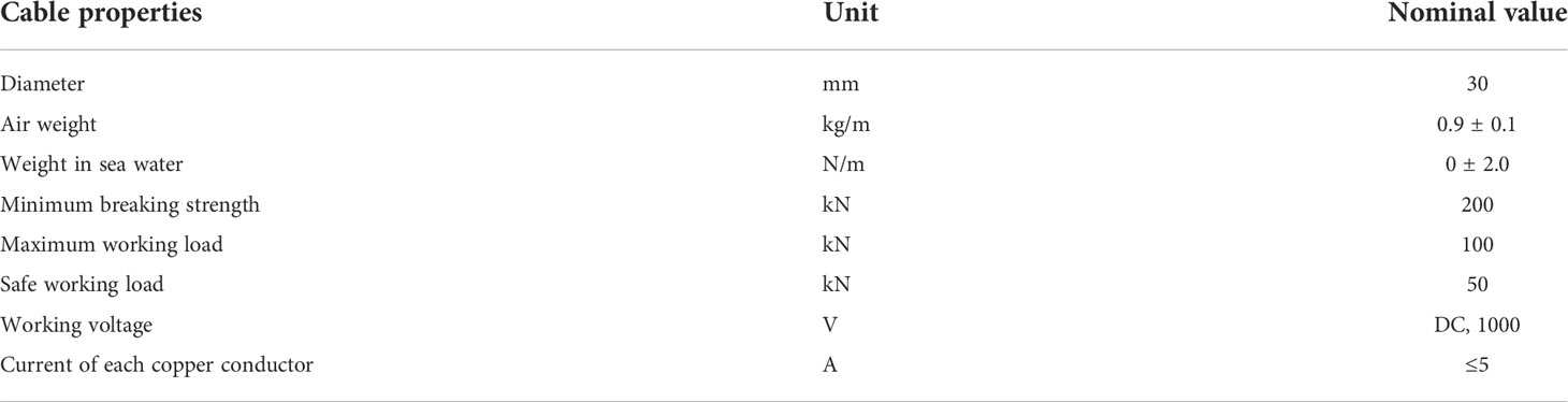
Table 4 Properties of the EOM cable.
Flexible connection joints
Considering the torque imparted by buoy rotation to the EOM cable, a slip ring is used to connect the EOM cable and the buoy. The cost of a photoelectric slip ring that can bear the mooring force and is custom-made would be too high. Therefore, we have to use an electric slip ring with 13 wires as a replacement, as shown in Figure 7. As a result, the optical signals need to be converted into electrical signals. The frequent swinging of the buoy also has a great influence on the cable at the joint. This kind of frequent vibration may lead to fatigue damage of the optical fiber; therefore, we had to design a universal joint to eliminate this vibration influence.
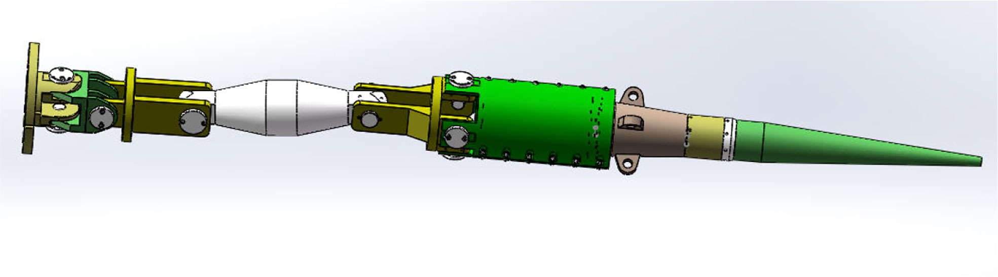
Figure 7 Flexible connection joints including the universal joint, slip ring and E/O electronic cabin.
We designed a flexible connection, as shown in Figure 8, where the buoy connects with the universal joint, and then the electric slip ring, and lastly the E/O electronic cabin. The load-bearing joint is vulcanized with the EOM cable, and the E/O electronic cabin is fixed on the load-bearing joint. The flexible connection of the benthic node is the same as the buoy, but the slip ring is not installed on the benthic node. The E/O electronic cabin is powered by the 375 VDC bus of the cable. At the benthic node, the E/O electronic cabin separates from the EOM cable as an 8-pin Ethernet connector for data transmission and a 3-pin copper-wire connector for power supply. Sea surface data transmission and power supply are integrated in the 13-wire watertight connector of the slip ring.
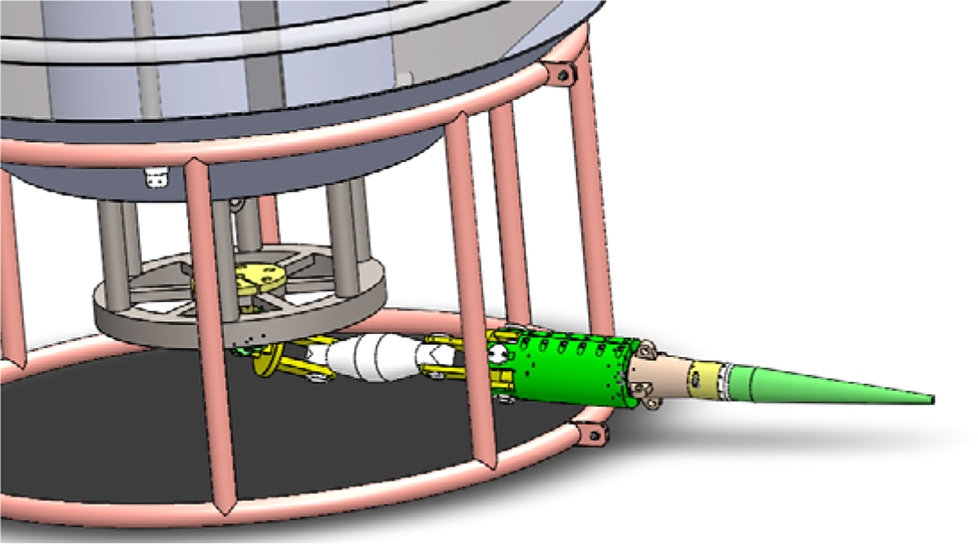
Figure 8 Connection of buoy and the flexible connection joints.
The advantages of this flexible connection joints are as follows:
1. The swing angle of the universal joint is 0~30°, which reduces the fatigue damage caused by the buoy swing to EOM cable, and realizes the flexible transition and connection.
2. Electric slip ring is utilized in the design to transmit signals and power. Affected by wind, wave and ocean current, the buoy will rotate irregularly on the sea surface. If the torsional torque generated by the buoy rotation is transferred to the mooring EOM cable, the mooring EOM cable will be knotted or twisted, which will easily cause the attenuation and failure of optical signal of the EOM cable.
3. The E/O electronic cabin converts optical signals into network signals. In this way, it is unnecessary to choose the optical fiber slip ring, especially the optical fiber slip ring have to bear tethering force. The design of the E/O electronic cabin reduces the cost and the risk of system failure; while it can also transmit video signals from benthic to the sea surface.
4. For the design of benthic node, in order to avoid underwater ROV plugging, we design the E/O electronic cabin and the universal joint for connection. For the system launch, we can connect the above component and modules, and deploy the benthic node, EOM cables and buoys in proper order.
Experiments and challenges
Experiments
In this section, we discuss experiments performed with the system. We do not utilize the ROV to perform the connection with the wet-mate connector because both the ROV tether and buoy EOM cable are hanging in the seawater, and these two cables may intertwine together under the influence of sea current. For the system design, we have considering the acoustic releaser and the buoyancy materials (above the benthic node), as shown in Figure 3B. So when we recovery the system, the mooring and the benthic node can float out to surface. But in the near shore experiment, we do not utilize it, mainly considering the following aspect:
1. While the anchor block (3 ton) and the buoyancy material (1.7 ton) is installed on the benthic node (1 ton), the total weight of the seabed node is close to 5.7 ton. Gross Registered Tonnage of the ship is 300 tons and the ship has a “A” Frame with the max 2.5 ton Lifting weight. So it is impossible to launch the benthic node with the anchor block, while the cost of large scientific research ships is huge.
2. The location of the near shore launch experiment is selected where the water depth less the 30 meter. So that, when recover the benthic, the diver can dive into the seafloor to hook the benthic node. Then we can pull the benthic node to the ship by the ship wire rope winch. We give the mooring diagram of deployed system as shown in Figure 9.
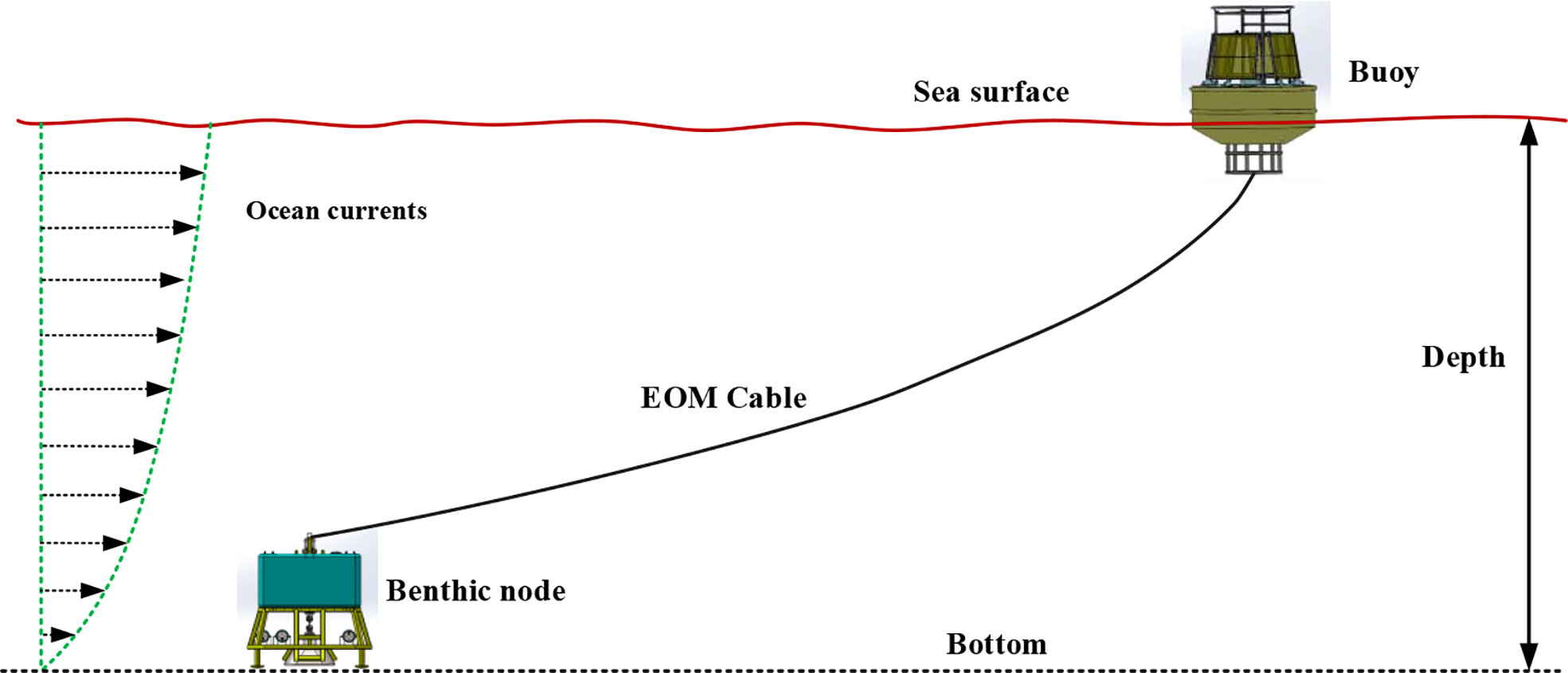
Figure 9 Mooring diagram of deployed system.
In 2017, a Rochester Engineered Cable was utilized in the experimental testing of the system. The system only integrated the ST5801GB-M1 wireless radio, acoustic communication, the benthic camera, and the sea surface camera at first, and the benthic node had a simple structural frame with a weight less than 300 kg. We had to use the anchor chain to moor the buoy, which is similar to Ref (Iannaccone et al., 2009), but we also bound the EOM cable and the anchor chain together with Kevlar rope (5 m each). The length of the anchor chain was approximately 1 m shorter than the EOM cable at each bundled section, so the optical fiber of the EOM cable would not be pulled off while the anchor chain was bearing the pull force from the seafloor anchor block. At the seafloor, there was a ~2 T anchor chain playing the role of anchor block to moor the buoy. Another ~50-m EOM cable on the seafloor was deployed far from the anchor block, so as to avoid the influence of the drifting of the anchor block and buoy. For near-shore experiments, we connected the buoy and the benthic node with the EOM cable from the harbor. The lifting capacity and height of the “A” frame of the mother ship was limited, so it was difficult to lift the buoy from the mother ship to the sea surface. We had to use a crane to lift the buoy into the water in the harbor, and then lifted the benthic node onto the mother ship. We then towed the buoy to a predetermined location and launched the benthic node to the seafloor with the “A” frame. We recovered the system in the opposite order, but we also had to let divers hook the seafloor junction box with Kevlar rope to bring it to the sea surface. Through the experiment, we achieved seafloor video transmission to the shore in real time and verified the acoustic communication with the underwater lander. The solar panels provided enough power for the system. The efficiency of the wind turbine was not high due to the low wind speed. The experimental results are given in Ref (Zhang et al., 2018). For prototype system design in Ref (Zhang et al., 2018), the cable terminal are fixed on the buoy bottom bracket. This rigid connection method is not applicable for the buoy launch and recovery. The rigid connection make the fiber of the EOM cable easily invalid. So we choose the universal joint as a replace for the flexible connection. The flexible connection brings great convenience to the system launch and recovery.
In 2018, we designed and manufactured the benthic node and the vectran-fiber cable, as shown in Figure 6B. Flexible connection joints and the vectran-fiber cable were first applied in experiments. The shore control interface is shown in Figure 10B and the buoy towing process is shown in Figure 10A. The benthic node had a weight as high as 4 tons, which could provide enough mooring force for the buoy. All the sensors and communication instruments were carried on the system. The EOM cable was 200 m in length, and the system was launched at a depth of 20 m. The power loss in the 200m cable length is about 0.35W. The launch and recovery method is similar with the experiment in 2017, but the experiment in 2018 has exposed some design and application problems. Firstly, we did not preset the on/off state of the seafloor video instruments with the software, and these instruments were normally on. The total power consumption is 230W, and the large power consumption modular including wireless radio, light, and camera. The system last four days. If the large power consumption modular are powered intermittently (10 minutes per 3 hours), the average power consumption of the system is about 80W. We improved the control software in 2019, and make the design of the control software more reasonable. The wireless radio also comprised high-power-consumption instruments, which led to a shortage of energy supply to the system several days after it was launched. Thus, the software should be optimized to preset the startup and shutdown of the instruments. Secondly, the EOM cable was too long for the system at a depth of 20 m. When we recovered the system after a month, superfluous cable was entangled on the cage of the benthic node. We also found that the outer bedding braid layer of the cable became worn, cracked, and wrinkled. Therefore, we had to choose a harder outer bedding braid layer for the EOM cable.
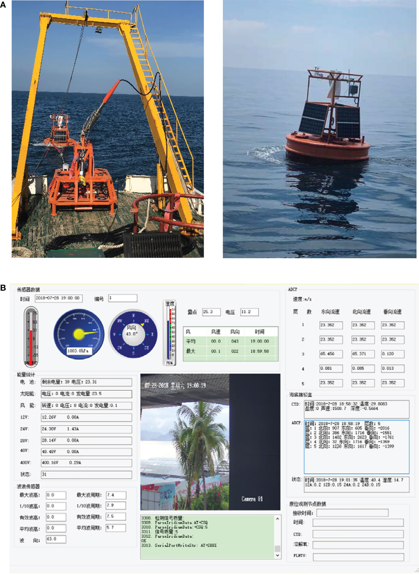
Figure 10 Recovery of the system and the shore control interface. (A) Towing and launch of the buoy. (B) The shore control interface.
In 2019, we launched the system again at a depth of 20 m with 60 m of remanufactured EOM cable. The location of the system is N18.285, E109.4723, and the shore center locate at E109.485601, N18.215604. So the transmission distance of the wireless radio is 7.8km. During the experiment, the sample data from the instruments of the sea surface and the sea benthic node were transmitted to the shore via iridium communication and Beidou communication continuously. Detailed information about the sample data is given in Ref (Wang et al., 2019). The observation data can be transmitted through Beidou and Iridium. The video data from the benthic node can be stored in the junction box, and it can be transmitted in real time through wireless radio. However, considering the large power consumption of seabed light, camera, and wireless radio, we verify the benthic image acquisition and transmission link, and we do not carry out continuous video data acquisition. In order to utilize this kind of cable in Deep Ocean, it required a special hydraulic winch for cable project construction. Compared with the steel-wire armored cable, the manufacturing technology of the selected vectran-fiber cable is not mature. Furthermore, the EOM cable is squeezed after winding on a hydraulic winch when it is tested at the factory, which will lead to the failure of optical fiber communication. Therefore, we delayed experimenting with this kind of application.
We have verified the technology of the whole system through the above experiments. In the mechanical structure design of surface buoy and the benthic node, universal joint is designed to realize the connection between cable and buoy. At the same time, the risk and cost of offshore experiments are reduced by means of towing buoys, offshore wharf installation, etc. The transmission of power flow and data flow from the sea surface to the benthic has been established. We build optical fiber communication, Ethernet communication wireless communication links to realize video data transmission. This provides a possibility for underwater acoustic observation in the future. Through many tests, the control module of the system is gradually stabilized. For the design of the EOM cables, we compare the metal armored cable and the vectran-fiber cable through the experiments, especially vectran-fiber cable, it provides a great possibility for the application of the systems in the deep sea. We have verified the reliability of the vectran-fiber cable in the near shore. For the buoy mooring, we design E/O electronic cabin and load-bearing electric slip ring, so as to eliminate the influence of the torque generated by the rotation of the buoy on the mooring EOM cable. These above optimizations solve the problems we meet in the experiments. And through the near shore experiments, we verify the reliability of the system.
Challenges
In this section, we discuss the challenges of the system and potential improvements.
First, whether the system can work for a long time depends largely on the working state of the EOM cable, which creates high requirements for its technology and utilization. Optical fiber communication is utilized for the MOOS prototype in Refs (Chaffey et al., 2001; Chaffey et al., 2005; Hamilton and Chaffey, 2005). at a depth of 4000 m, when the cable is suspended in water. Further, the fiber is affected by various external forces and vibrations under long-term continuous operation. These application scenarios bring more stringent requirements for the manufacturing of the EOM cable. As shown in Ref (Palanza et al., 2017). Ethernet (CATV) cables can be used for data transmission, but this method will lead to a reduction of transmission rate as the cable length becomes longer. Coaxial cables are another option for underwater long-distance communication. As shown in Ref (Makris et al., 2014), a real-time on/offshore seismic and tsunami network with coaxial cables was established based on seismic and tsunami telemetry buoys.
Secondly, both a steel armored cable and a net buoyancy cable (Nylon and Vectran fibers) are used in this kind of system. However, the manufacturing of net buoyancy cables is not as mature as that of steel armored cables. Furthermore, the coordination of the cable and winch is also a difficulty, and improper operation will lead to cable extrusion and damage. As shown in Ref (Chaffey et al., 2005). ROV and wet-plug technology are selected for launching this kind of system, which significantly increases costs. The problem with steel armored cables is their weight; therefore, we should design underwater float balls to balance the gravity of steel armored cables. Of course, this will increases the difficulty of system launch and recovery.
Thirdly, rubber hoses Ref (Mellinger et al., 2003). are useful for reducing the impact of buoy vibration on the cable, especially for the instantaneous impact of mooring force. This was a key point of the EOM cable in Ref (Frye et al., 2004), where the elongation of the nylon at break was between 15%~28%, whereas the copper and optical elements stretched in the cable no more than 0.5%. Thus, the fiber may break before the nylon cable reaches its maximum elongation. As a result, communication via the cable is interrupted. A nylon-cord reinforced rubber hose can provide additional compliance during mooring and decrease dynamic tension under wave action. At the moment, we do not carry out long-term observations in the deep sea, so we have not added rubber hosing in the flexible connection joints.
Fourth, a slip ring is necessary in the flexible connection joints. We use a slip ring to eliminate the torque on the EOM cable that is caused by the rotation of the buoy. However, we have to carefully consider the torsion resistance of the EOM cable if we do not add the slip ring to the flexible connection joints. The EOM cable is made of even armoring layers so as to avoid the residual torque existing on the cable; especially, buoy rotation may increase the residual torsion on the cable.
Fifth, the renewable energy provided by the solar panels is limited. The efficiency of photovoltaic power generation is ~10%, and the power supply depends on how many solar panels can be equipped on the buoy. For observation systems with a high power consumption, additional solar panels are needed, which may require the manufacturing of a buoy with a larger size. As the buoy’s structural size increases, the difficulty of launching and recovery will gradually increase, which is also an aspect we need to consider before such a system is designed.
Sixth, the launch and recovery of the system are difficult compared to traditional buoys. We have to utilize a gravity anchor to moor the buoy, but not a grip anchor. As a result, the gravity anchor is too heavy to launch from the mother ship. The “A” frame must have sufficient lifting capacity and height for the launch of the buoy. In addition, a hydraulic winch is needed to launch the EOM cable. These requirements make it difficult to choose a suitable mother ship. As shown in Ref (Clark and Kocak, 2011). Cyprus-TWERC uses three vessels and an ROV to work together to deploy the anchor, the buoy, and the riser cable. The buoy and riser cable plug into the anchor interface through ROV wet-mate connectors. While meeting the requirements, we should consider the modular design from the view of system launch and recovery.
Discussion and conclusion
The Mooring Buoys Observation System for Benthic with Electro-Optical-Mechanical Cable, also known as MBOSBC, is designed for ocean observation and communication networks of the South China Sea. The system records signals from the seafloor and sea surface. We fully integrate the sea surface and seafloor platforms, including mechanical design, control and data management, power supply, communication, and system launch and recovery. We developed this system and technology as a supplemental mode for traditional buoy observation and seabed observation networks. We integrate Beidou, wireless, and iridium communication, as well as an optical fiber communication link, so as to realize real-time communication for three-dimensional ocean observation and real-time transmission of underwater video from the ship or the coast. We utilize acoustic communication to collect sample data from other benthic observation platforms, such as other isolated benthic observation nodes and AUVs. Through experiments, we verified the effectiveness of the mooring buoy system for seafloor observation. At present, MBOSBC is the subject of a feasibility study of communication networks of regional ocean observation; in the future, it will be integrated into the seafloor observation systems of the South China Sea for application.
Data availability statement
The original contributions presented in the study are included in the article/supplementary material. Further inquiries can be directed to the corresponding authors.
Author contributions
SZ contributed to conception and design of system and the manuscript preparation. CT and FZ contributed to the experiment. All authors contributed to manuscript revision, read, and approved the submitted version.
Funding
This work is supported by State Key Laboratory of Tropical Oceanography, South China Sea Institute of Oceanology, Chinese Academy of Sciences (Project No. LTO 2207); Hainan Province Basic and Applied Basic Research Program (Natural Science) high-level Talents Project of China (2019RC262); Natural Science Foundation of China (No. 51809255): Research on tracking strategy of ocean cold eddy-upwelling with AUVs; National Natural Science Foundation of China, National Key Research And Development Plan of China (No. 2018YFC0307900), and China Strategic Priority Research Program of the Chinese Academy of Sciences (Grant No. XDA13030301). The authors would like to thank the reviewers for their careful work.
Conflict of interest
The authors declare that the research was conducted in the absence of any commercial or financial relationships that could be construed as a potential conflict of interest.
Publisher’s note
All claims expressed in this article are solely those of the authors and do not necessarily represent those of their affiliated organizations, or those of the publisher, the editors and the reviewers. Any product that may be evaluated in this article, or claim that may be made by its manufacturer, is not guaranteed or endorsed by the publisher.
References
Chaffey M., Bird L., Erickson J., Graybeal J., Hamilton A., Headley K., et al. (2005). MBARI’s buoy-based seafloor observatory design. MTS/IEEE Techno-Ocean 4, 1975–1984. doi: 10.1109/OCEANS.2004.1406447
Chaffey M., Mellinger E., Paul W. (2001). “Communications and power to the seafloor: MBARI’s ocean observing system mooring concept,” in MTS/IEEE oceans 2001. an ocean odyssey. conference proceedings. (Honolulu, HI, USA: IEEE Oceans) 2001, 2473–2481. doi: 10.1109/OCEANS.2001.968389
Clark A. M., Kocak D. M. (2011). Installing undersea networks and ocean observatories: The CSnet offshore communications backbone (OCB) (Waikoloa, HI), 1–9. OCEANS ‘11 MTS/IEEE KONA. doi: 10.23919/OCEANS.2011.6107087
Clark A. M., Kocak D. M., Martindale K., Woodroofe A. (2009). “Numerica modeling and hardware-in-the-loop simulation of undersea networks, ocean observatories and offshore communications backbones,” in Proc. MTS/IEEE OCEANS 2009 conference. (Biloxi: IEEE Oceans), 2009, 1–11.
Delaney J., Heath G. R., Chave A. D., Howe B. M., Kirkham H., et al. (2000). NEPTUNE: real-time ocean and earth sciences at the scale of a tectonic plate. Oceanography 13 (2), 71–79. doi: 10.5670/oceanog.2000.37
Frye D., Hamilton A., Grosenbaugh M., Paul W. (2004). Deepwater mooring designs for ocean observatory science. Mar. Technol. Soc J. 38 (2), 7–20. doi: 10.4031/002533204787522857
Georgiou G., Clark A. M., Zodiatis G., Hayes D., Glekas D. (2010). “Design of a prototype Tsunami Warning and Early Response system for Cyprus -TWERC”. 2010 in OCEANS `10 IEEE SYDNEY. Sydney, NSW, Australia: IEEE Oceans, 2010, 1–5. OCEANS ‘10 IEEE SYDNEY. doi: 10.1109/OCEANSSYD.2010.5603936
Grosenbaugh M., Walter P., Frye D., Farr N. (2006). Development of synthetic fiber-reinforced electro-optical-mechanical cables for use with moored buoy observatories. IEEE J. Ocean. Eng. 31, 574–584. doi: 10.1109/JOE.2005.850937
Hamilton A., Chaffey M. (2005). “Use of an electro-optical-mechanical mooring cable for oceanographic buoys: Modeling and validation,” in International conference on ocean, offshore and Arctic engineering. Halkidiki, Greece: Ocean, Offshore and Arctic Engineering Division, 2, 897–903.
Han S. M., Grosenbaugh M. A. (2006). On the design of single-point cable-linked moorings for ocean observatories. IEEE J. Ocean. Eng. 31 (3), 585–598. doi: 10.1109/JOE.2005.850917
Iannaccone G., Guardato S., Vassallo M., Elia L., Beranzoli L., et al. (2009). A new multidisciplinary marine monitoring system for the surveillance of volcanic and seismic areas. Seism. Res. Lett. 80, 203–213. doi: 10.1785/gssrl.80.2.203
Makris J., Papoulia J., Tsambas A. (2014). A real-time seismic and tsunami network in the kyparissiakos gulf, Greece, bollettino di geofisica teorica ed applicata, 55(2)561–587.
Martino P. D., Guardato S., Tammaro U., Vassalo M., Iannaccone G., et al. (2014). A first GPS measurement of vertical seafloor displacement in the campi flegrei caldera (Italy). J. Volcanol. Geotherm. Res. 276, 145–151. doi: 10.1016/j.jvolgeores.2014.03.003
Mellinger E., Erickson J., Hamilton J. A., Chaffey M., McBride L. (2003). “Dynamic modeling and actual performance of the moos test mooring,” in Proceedings of the IEEE/MTS OCEANS conference. (San Diego, CA: IEEE Oceans), 2003, 2574–2581.
Palanza M., Petillo S., Matthias P. (2017). Ocean observatories initiative coastal surface mooring technology. IEEE Conf. Oceans, 2003, 1–4. doi: 10.1109/OCEANSE.2017.8085008. Aberdeen.
Sekino H., Clark A. M. (2003). A near real-time buoy telemetry system for observation of marine earthquake/crustal deformation in Japan. IEEE Int. Workshop Sci. Use Submarine Cables Related Technol. 2003, 266–271. doi: 10.1109/SSC.2003.1224159
Smith L. M., Barth J. A., Kelley D. S., Plueddemann A., Rodero I., Ulses G. A., et al. (2018). The ocean observatories initiative. Oceanography 31 (1), 16–35. doi: 10.5670/oceanog.2018.105
Trowbridge J., Weller R., Kelley D., Dever E., Plueddemann A., Barth J. A., et al. (2019). The ocean observatories initiative. Front. Mar. Sci. 6, 1–22. doi: 10.3389/fmars.2019.00074
Wang H., Yang W., Xin Y., Zhang S. (2019). A data management method for remote and long-term seafloor observation system. Mar. Geod. 43 (1), 1–22. doi: 10.1080/01490419.2019.1673265
Yu J., Zhang S., Yang W., Xin Y., Gao H. (2020). Design and application of buoy single point mooring system with electro-optical-mechanical (EOM) cable. J. Mar. Sci. Eng. 8 (672), 1–25. doi: 10.3390/jmse8090672
Keywords: electro-optical-mechanical (EOM) cable, seafloor junction box, Buoy, ocean observation, mooring
Citation: Zhang S, Tian C and Zhou F (2022) Ocean observation system design of mooring buoy and benthic node with electro-optical-mechanical cable. Front. Mar. Sci. 9:1018751. doi: 10.3389/fmars.2022.1018751
Received: 13 August 2022; Accepted: 17 October 2022;
Published: 28 October 2022.
Edited by:
Atmanand M. A., Indian Institute of Technology Madras, IndiaReviewed by:
Sundar R., National Institute of Ocean Technology, IndiaArul Muthiah, National Institute of Ocean Technology, India
Copyright © 2022 Zhang, Tian and Zhou. This is an open-access article distributed under the terms of the Creative Commons Attribution License (CC BY). The use, distribution or reproduction in other forums is permitted, provided the original author(s) and the copyright owner(s) are credited and that the original publication in this journal is cited, in accordance with accepted academic practice. No use, distribution or reproduction is permitted which does not comply with these terms.
*Correspondence: Shaowei Zhang, enN3c2lhQDEyNi5jb20=; Chuan Tian, dGlhbmNAaWRzc2UuYWMuY24=; Fenghua Zhou, emhvdWZoQHNjc2lvLmFjLmNu