 Yunlong Wei1*
 Deqing Wang2
- 1Department of Electronic Information Engineering, School of Physics and Information Engineering, Fuzhou University, Fuzhou, China
- 2Key Laboratory of Underwater Acoustic Communication and Marine Information Technology (Xiamen University), Ministry of Education, Xiamen, China
In this paper, the multichannel medium access control (MAC) problem in distributed underwater acoustic sensor networks (UASNs) were investigated. Compared with single-channel MAC protocols in terrestrial radio networks, there exist multichannel hidden terminal problem and long-delay hidden terminal problem in multichannel MAC protocol due to long propagation delay in UASNs. In addition, energy constraint makes channel allocation a challenging problem in distributed UASNs. To solve these aforementioned problems, a new multichannel MAC protocol, called graph coloring-based multichannel MAC protocol (GCMAC) is present. The protocol GCMAC is a synchronized MAC protocol which splits the time into three phases, namely, channel negotiation phase, channel selecting phase and data transmission phase. Specially, the rule for selecting channel is carefully designed based on graph coloring theory to avoid collision and maximize the utilization rate of channels in channel selecting phase. Simulation results show that GCMAC can greatly improve the system throughput and energy efficiency by effectively solving the hidden terminal problems and channel allocation problem.
1. Introduction
Underwater acoustic sensor networks (UASNs) have attracted extensive attention in the last couples of years (Cui et al., 2006; Jahanbakht et al., 2021). On the one hand, UASNs have been found in wide aquatic applications, such as oceanographic data collection (e.g., temperature, salinity, and zonality), field monitoring and disaster prevention. On the other hand, the adverse underwater environments posed severe challenges at almost every level of the protocol stacks, among which efficient medium access control (MAC) is one of the most fundamental issues (Ansari et al., 2015).
Compared with the terrestrial counterpart, there are some differences which will result in significant influence on network protocol design in underwater environment. Firstly, the propagation speed of acoustic signals in water is about 1.5×10³m/s, which is five orders of magnitude lower than radio propagation speed. This brings obvious propagation delay in underwater communications. Secondly, the available bandwidth is extremely limited and it is distance/frequency dependent. For example, there are only a few hundred kHz for short range, a few 10kHz for medium distance, and a few hundred Hz for long range (Huang et al., 2018). Lastly, severe multipath spread and high Doppler shift may cause low communication rate and unreliable physical layer. Due to these unique characteristics owned by underwater acoustic channels, the MAC protocols designed for terrestrial radio networks could not be adapted directly, and a significant amount of research efforts (Chen et al., 2014; Jiang, 2018) for MAC in UASNs have been inspired in the last ten years. Most of those protocols focus on single-channel network scenarios, whereas the MAC protocols with a single channel could not eliminate the interference between control packets and data packets due to long propagation delay. Consider that the multichannel MAC protocols have the capability of transmitting data in parallelly, leading to higher network throughput, lower channel access delay, smaller energy consumption, some research on multichannel MAC protocols for UASNs have been conducted. Therefore, we focus on the design of multichannel MAC protocols adapted to the unique characteristics of underwater acoustic channels. Specifically, the contribution of this paper mainly includes:
● A multichannel MAC, called Graph Coloring-based Multichannel MAC (GCMAC), is put forth to tackle the special hidden terminal problem resulted by the unique underwater acoustic channels. The hidden terminal problem consists of multichannel hidden terminal one and long delay hidden terminal one. In GCMAC, a synchronized scheduling mechanism is adopted and the data transmissions are originated by the receiving nodes.
● In order to increase the channel utilization, we identified the channel allocation problem based on the theory of graph coloring by taking physical transmission model into account. Furthermore, a channel-selection rule is designed to assist the data negotiation for GCMAC.
The rest of this paper is organized as follows. In Section 2, we review related work on multichannel MAC protocols for UASNs. Then in Section 3, we discuss multichannel problems needing to be solved in this paper. After that, we present a system model and describe the GCMAC in detail in Section 4 and 5. Simulation results are presented in Section 6. Finally, Section 7 gives a summary of this paper.
2. Related work
Multichannel MAC protocols for underwater acoustic networks have also aroused significant research interest recently. The authors in (Zhou et al., 2012) proposed a new MAC protocol called Cluster based Underwater MAC(CUMAC) for long-delay multichannel underwater sensor networks. They investigated triple hidden terminal problems, i.e., multichannel hidden terminal, long-delay hidden terminal and traditional multi-hop hidden terminal. In order to increase energy efficiency, the authors in (Chao et al., 2015) proposed a dynamic duty-cycled multiple-rendezvous multichannel medium access control (DMM–MAC) protocol that is suitable for transmitting bursty traffic in a duty-cycled UWSN. Consider that the contention-free approach can achieve high performance by avoiding the collisions at the MAC layer, The authors in (Hsu et al., 2009) proposed a TDMA (Time Division Multiple Access) -based MAC scheduling scheme called ST-MAC for underwater sensor networks. They constructed the Spatial-Temporal Conflict Graph (ST-CG) to describe the conflict delays among transmission links explicitly, thus the protocol ST-MAC is modeled as a new vertex coloring problem of ST-CG. Similarly, GC-MAC (Alfouzan et al., 2019) employs TDMA-like approach by assigning separate time-slots, colors, to every individual sensor node in every two-hop neighborhood. The protocol MC-UMMAC (Bouabdallah et al., 2017) is also an energy efficient MAC protocol that aims at achieving a collision free communication. It operates on a single slotted control channel to avoid the missing receiver problem and multiple data channels to improve the network throughput.
Among these works mentioned above, we could find that the channel allocation is considered a critical issue left to be solved in multichannel MAC for UASNs.
Channel or spectrum allocation has a significant impact on the performance of multichannel communication. The authors in (Wang and Liu, 2005) studied the dynamic channel allocation for open-spectrum wireless networks. Multi-frequency Media Access Control for Wireless Sensor Networks protocol (MMSN)is the first multi-frequency MAC protocol specially designed for wireless sensor networks. They also conducted a complete study on the tradeoffs among physical frequency requirements, potential conflict reduction and communication overhead during frequency assignment. While the authors in (Fitzpatrick et al., 2004) described two new online channel assignment algorithms for networks based on a regular hexagonal layout of cells. DRAND (Rhee et al., 2009) is a randomized time slot scheduling algorithm, which is a distributed implementation of RAND (Ramanathan and Engineer, 1997). The algorithm is suitable for a wireless network and could be used for frequency or code scheduling. The authors in (Saifullah et al., 2014) proposed a set of distributed algorithms for near optimal channel allocation in wireless sensor networks with theoretical bound. Inspired by these aforementioned works, we address the channel allocation problem based on graph coloring theory (Kuhn and Wattenhofer, 2006) in distributed topology to achieve high energy efficiency.
3. Problems in multichannel MAC protocol
3.1. Hidden terminal problem
There is multichannel hidden terminal problem and long delay hidden terminal problem in multichannel protocols (Zhou et al., 2012).
Figure 1 shows that when node a is to send data to node b, Request to send (RTS) and Clear to send (CTS) control packets may interact in the control channel. Data channel 1 is selected as the data transmission channel, and the data transmission is switched to data channel 1. In the channel negotiation process of node a and node b, node c is communicating with node d through data channel 2, and it does not know that nodes a and b have selected data channel 1 as the ensuing data transmission. Therefore, if node c selects data channel 1 in the next round of communication, then there may be data packet collision with node a. This is the multichannel hidden terminal problem.
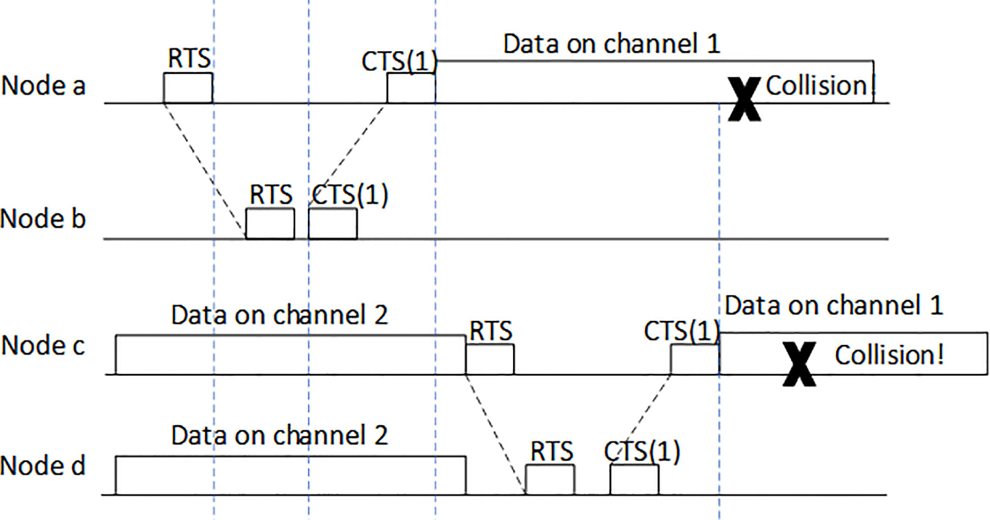
Figure 1 Multichannel hidden terminal problem.
In Figure 2, nodes a and b select data channel 1 when interacting control packet. At the same time, nodes c and d are also interacting control packet to select an idle data channel. Due to long transmission delay, the control packet of node b reaches node d after node d responds node c. Before that, node d mistakes data channel 1 as an idle one, and selects it as the channel for ensuing data transmission. It is clear that the data packets sent by nodes a and d collide at node b. This is the long delay hidden terminal problem.
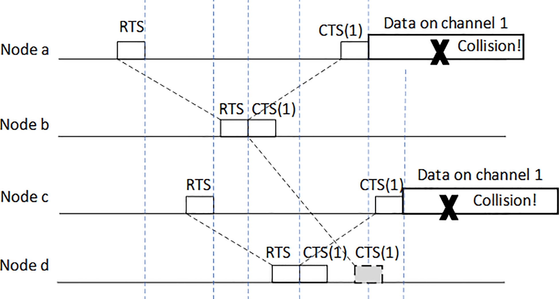
Figure 2 Long delay hidden terminal problem.
3.2. Channel allocation problem
In (Ramanathan and Engineer, 1997), a unified framework in the multi-hop network environment was defined based on summarizing previous research. Since the assignable channels are discrete, they can be represented by different colors. Therefore, a channel assignment problem is converted into a graph coloring problem. Firstly, the following definition is made.
Definition 1. A graph G, denoted as G = (V,E), with node set V = {v1,v2,⋯⋯,vn} representing the network node set; and directional edge set E = {e1,e2,⋯⋯,em} representing the inter-node links. The nodes associated with the same edge are neighboring vertices in the network.
Definition 2 (k-coloring). The k vertex coloring of G represents a distribution of k kinds of colors, i.e.,1,2,⋯,k, to all nodes of G. If any two neighboring nodes get different colors, the coloring is called normal. With respect to a network, the channel allocation scheme for neighboring nodes is available, since the neighboring nodes are assigned different channel number.
Definition 3 (Color number). The color number χ of G represents the minimum k such that G is k-color.
Definition 4 (Maximum degree). The maximum degree Δ of G v is any node of G, and the number of edges associated with it is called the degree of v, and denoted as d(v). Then, Δ = max{d(v)|v ∈ V}.
Definition 5 (Hop distance). The hop distance d(u,v) between two vertices u,v is the length of the reachable path linking the two vertices (using the reachable length of a single hop as the unit). The two nodes with a hop distance being 1 are neighboring nodes mutually. Neighboring nodes can directly communicate or become potential interfering nodes.
According to the above definitions, channel allocation problem is converted into a coloring problem of graph vertices, where the constraint condition is the premise that the channel allocation is available.
It can be known from the underwater acoustic signal attenuation model that the attenuation degrees of signals with different frequencies are different under the condition that communication distance is unchanged. We define the sound source emission spectrum level as SL,define the attenuation loss spectrum level as TL, define the environment noise spectrum level as NL, and define the signal bandwidth as B. Then the signal-to-noise ratio (SNR) (in dB) represented in spectrum level is
When receiving node receives signals, the other nodes using the same frequency band to communicate will interfere with the data being received. These nodes are called interference nodes. We define the distance between the sending and receiving node pair as communication distance, denoted as Rd, and define the distance between interference node and receiving node as interference distance, denoted as Ri. The distance between the sending and receiving node pair in communication in the form of signal to interference noise ratio (SINR) represented by energy is
where Prs is the power of received signal; Pri is the power of interference signal; and is the power of environment noise. Figure 3 shows the SINR versus interference distance. In the figure, the transmission power is adjusted according to different communication distances, so that the interference-free SINR is 10dB. Meanwhile, to facilitate the comparison of SINRs with different communication distances, the interference distances Ri are normalized with respect to communication distances Rd.
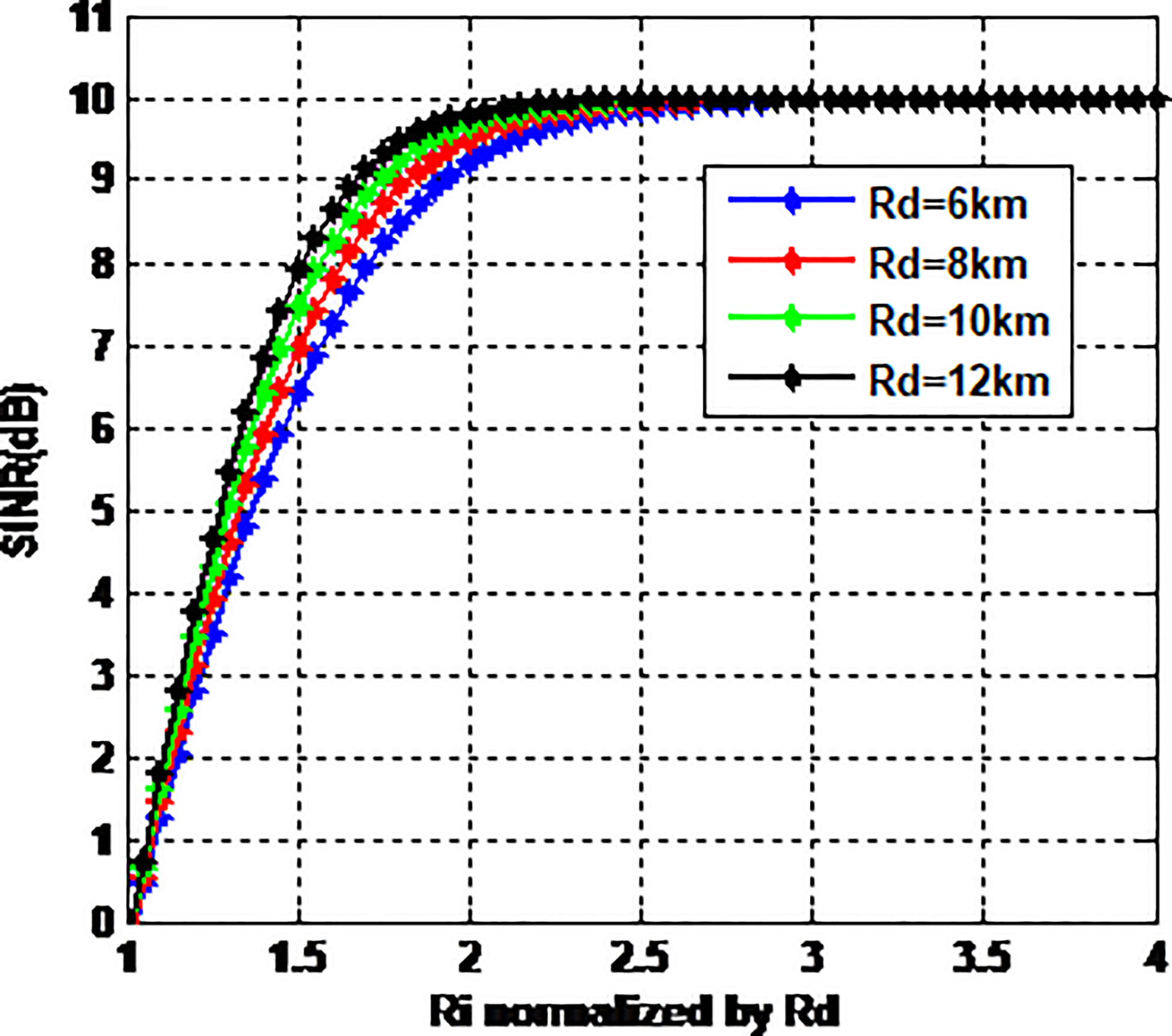
Figure 3 SINR versus interference distance.
When the interference node is far away from the receiving node, SINR will be larger. When Ri is two times of Rd, SINR is close to that of interference-free cases. In such situations, the interference nodes have almost no effect on receiving nodes. So, the following interference constraint condition is defined.
Definition 6 (Interference constraint condition). Let f be the mapping for distributing the vertices V(G) of graph G, with channel number set {0,1,2,⋯}. The mapping is denoted as f :V(G)→{0,1,2,⋯}. It satisfies: for any two nodes x,y, if d(x,y) = 1, then |f (x) – f (y)|≥ 2; if d(x,y) = 2, then |f (x) – f (y)|≥ 1.
The constraint condition of Definition 6 is the graph theory model in frequency allocation research——L(2,1) label (Chang and Kuo, 1996). The L(2,1) label problem is an NP-complete problem. In this paper, the research object is the MAC protocol in distributed networks. Therefore, distributed algorithms are adopted for channel allocation. Compared with concentrated algorithms, distributed algorithms can only obtain the information of neighboring nodes. Therefore, in limited communication phases and channels, it is more difficult to obtain coloring scheme satisfying the requirements. FirstFree is a basic distributed Δ+1-coloring algorithm, in which each node collects the existing coloring information of neighboring nodes and chooses an unused color for coloring. Since the maximum degree of a graph is Δ, it is guaranteed that we can use Δ+1 colors for available coloring. Its drawback is that if there are n nodes in the graph, then it is needed to execute the FirstFree algorithm n times, and no two or more nodes can be simultaneously colored in each round of coloring. It is clear that multiple rounds of communication reduces energy efficiency, prolongs control phase, and reduces the effectiveness of data transmission. Ideally, one round of communication is adopted to complete channel allocation. It can be mathematically proved that there exist possible coloring schemes when using only one round of communication. For example, it was proved in [31] that the upper bound of color number using one round of communication is 5Δ2log n. A distributed single-round coloring algorithm with an upper color number bound of Ω(Δ2/log2Δ+log m) is proposed, where m is the initial color number. In this case, the number of needed colors is much greater than Δ+1, and the available narrow bandwidth of underwater acoustic environment makes the underwater acoustic nodes unable to provide the required number of channels. Therefore, completing the channel allocation for a limited number of channels in only one round of communication is the major difficulty and key to multichannel MAC protocol design for UASNs.
4. System model
Consider an underwater acoustic sensor network for environment surveillance. N = I×J sensor nodes (SNs) are evenly distributed in a sea area to monitor the physical quantities, such as temperature, salinity and water velocity. The raw sensed data of each SN are fused at the aggregation node away from the surveillance region. The chart of the physical quantities is drawn and shown in Figure 4A [33].
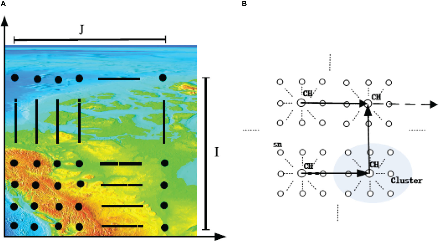
Figure 4 Network model. (A) Surveillance region where N SNs are distributed; (B) Clustered communication of regular network.
In this study, the SNs in the surveyed sea region communicate in the form of virtual clusters. Several SNs constitute a virtual cluster and select a cluster head (CH). The CH firstly collects sensor data in the cluster, and multi-hop communication is performed between clusters. The multichannel protocol established in this study completes the inter-cluster communication, as shown in Figure 4B, where arrows indicate the routing of data transmission.
The protocol is based on the following hypotheses:
(1) Each node is only equipped with a half-duplex transceiver, and sending and receiving cannot be simultaneously performed. In the same time, a node can only work in one channel. When a node is intercepting a certain channel, it cannot perform carrier sense for other channels. The transceiver can dynamically switch needed channels.
(2) According to different frequencies, n sub-channels are divided, with nodes transmitting data packets in sub-channels. No special control channel is set for control packets. Control packets are transmitted in the whole band.
(3) The whole network has a unified clock.
(4) Each CH node has at most N neighboring CHs within one hop as its neighboring nodes. A maximum transmission range is also set, so that the maximum transmission delay between neighboring nodes is known, and denoted as τmax.
(5) In one data transmission cycle, the underwater acoustic links are bilateral symmetry, and the link quality remains basically unchanged.
5. Protocol description
The MAC protocol designed in this study tries to solve the channel hidden terminal problem and channel allocation problem in multichannel protocols. To solve the channel hidden terminal problem, a synchronized scheduling mechanism is adopted. The receiving node is set as the viewpoint to intercept the working state information of the interference nodes among neighboring nodes, and choose channels without interference nodes to transmit data. The solution of the channel allocation problem is based on graph coloring theory, and a two-step strategy is adopted, namely, “initial allocation” and “dynamic adjustment”.
5.1. Synchronization working process
As shown in Figure 5, the horizontal axis represents time, denoted as symbol t; while the vertical axis represents frequency, denoted as symbol f. The protocol divides the time axis into repeated frames, denoted as Frame 1, Frame 2, and so on. Each frame represents a beacon period, and each beacon period is composed of three stages, namely, transmission negotiation stage, channel selection stage and data transmission stage. The transmission negotiation stage is made up of transmission request and transmission response, with TTR representing the duration. The propagation delay of transmission request and transmission response is set to the maximum propagation delay. The channel selection stage is made up of selection request and selection response, with TCS representing the duration. The propagation delay of selection request is set to the twice of maximum propagation delay, while the propagation delay of selection response is set to the maximum propagation delay. The data transmission duration is denoted by TD, with the propagation delay of data transmission set to the maximum propagation delay. The protocol divides the available frequency resource into 13 channels, which are channel 1 to 13, shown in Figure 5. The frequency resource is used as distributable resource. However, the distributable resource is not limited to frequency resource, it also includes time, code channel, etc.
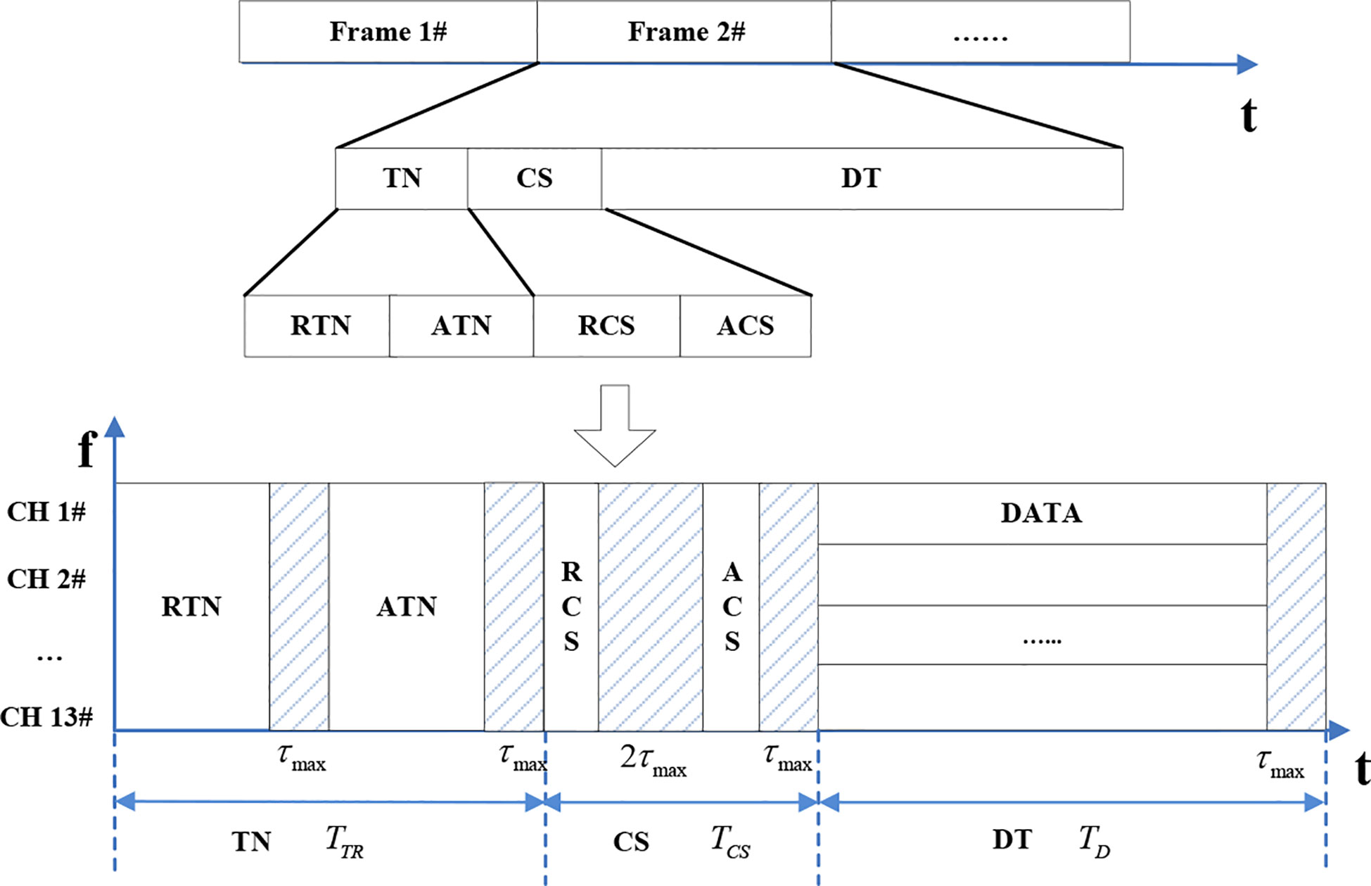
Figure 5 Synchronized work timing with frames being cycles.
First, the nodes with sending requests send control packet RTN in the transmission negotiation stage. The ID information of the source node and sink node is loaded in the control packet RTN. ID is the identification of nodes, and each node has a unique ID. The sink node adopts a kind of appropriate scheduling strategy to respond to control packet ATN. The ID information of source node and sink node is loaded in the control packet ATN, and the relationship of transmission node pair is thereby established. Second, the sending node of the sending and receiving node pair with established transmission relationship sends channel selection request control packet RCS in the channel selection stage. The ID information and coordinate information of the source node and sink node are loaded in the control packet RCS. The receiving node of the node pair not only receives the RCS packet from the sending node, but also receives other RCS packets from neighboring nodes. At this moment, sink nodes allocate channels, and respond with control packet ACS. The Channel group information ready for transmission is loaded in the control packet ACS. Finally, the data are transmitted, and transmission nodes transmit data packets in the channel group determined by the negotiations of sending part and receiving part.
It can be concluded from the above timing design that the designed multichannel MAC protocol is a kind of protocol which first competes for transmission and then chooses channels, which is contrary to Multichannel MAC protocol (MMAC) (So and Vaidya, 2004). The reason is that in the underwater acoustic network environment with long propagation delay, performing competitive transmission first not only makes it easy to sense the working status of each node, but also provides the ensuing channel selection with accurate global information and ensures that the selected channels do not collide among neighboring nodes. Therefore, the negotiation mechanism in the transmission negotiation stage is essential.
5.2. Transmission negotiation
Nodes with sending tasks randomly select a moment to send control packet RTN in transmission request sub stage. The ID information of the source node and sink node is loaded in the control packet RTN. At this stage, sending/receiving collision or receiving/receiving collision may happen. Sending/receiving collision means that a node has successfully sent RTN packet and received RTN packet from another node. Receiving/receiving collision means that a node has successfully received multiple RTN packets from other nodes. As shown in the bottom left of Figure 6, node A has successfully received RTN packets sent from nodes B and C successively, and it has to select one node of the two to respond. This is called receiving/receiving collision. As shown in the top left of Figure 6, node A has successfully received RTN packet sent from node C, and also has sent RTN packet to node B. It has to decide whether to respond to node C. This is called sending/receiving collision.
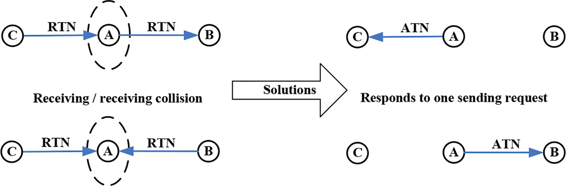
Figure 6 Transmission negotiation mechanism.
The solution to sending/receiving collision is to give priority to respond the sending request of the neighboring node, as shown in the top right of Figure 6. Node A selects node C as the sink node for sending response packet ATN. The solution to receiving/receiving collision is to respond to one sending request of the neighboring nodes, as shown in the bottom right of Figure 6. Node A selects node B as the sink node for sending response packet ATN, and ignores node C.
5.3. Rulers for selecting channel
For convenience, the network graph is redefined as follows:
Definition 7. Network graph G = (V,E,a,b), where V is the node set; E is the one-hop link set of nodes; a is the minimum interval between the channels allocated for neighboring nodes, and b represents the minimum interval between the channels allocated for two nodes with hop distance being 2. According to the above definition, the channel allocation algorithm in this study is divided into two stages, namely, “initial allocation” stage and “dynamic adjustment” stage. First, when the clusters are formed, each CH sets the sink as the center, and defines a coordinate for itself according to its geographical location. Since a regular rectangle network is adopted in this study, each node can easily obtain its coordinate according to its location. The labeling result of nodes is shown in Figure 7.
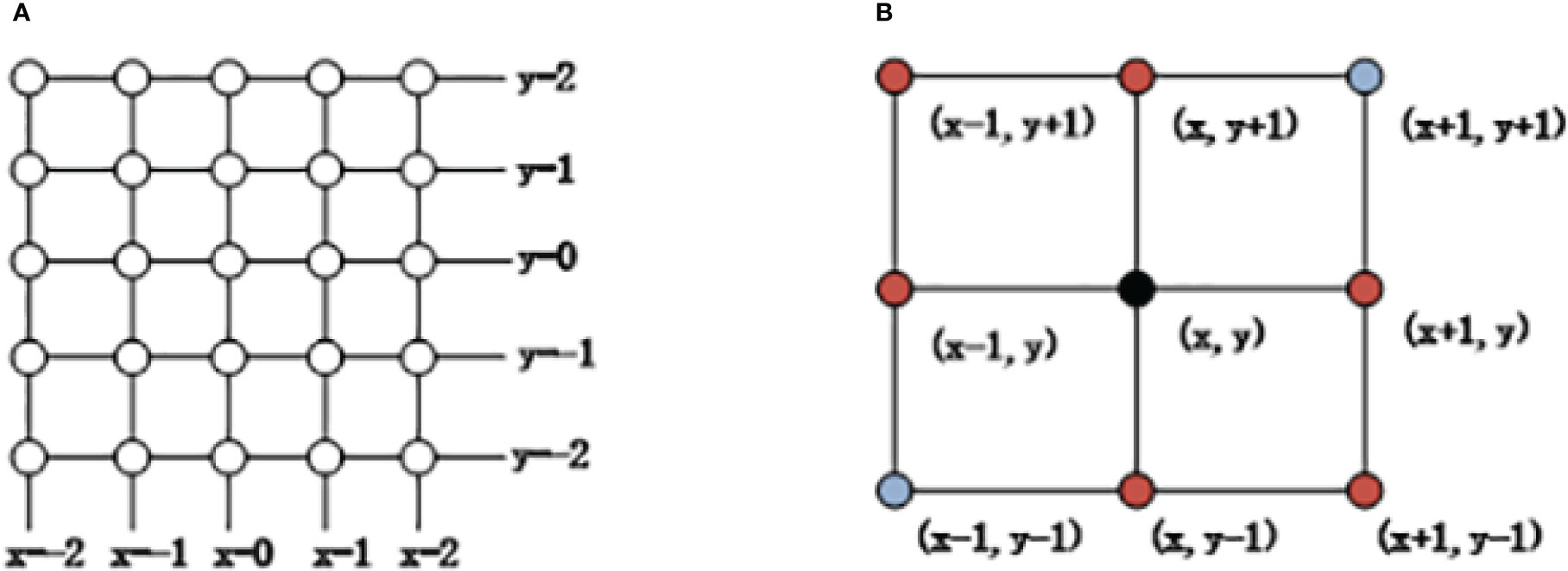
Figure 7 Labeling based on geographical locations of nodes. (A) Node coordinates (B) Coordinate value relations of neighboring nodes.
Then, allocate a channel number f (x,y) for the node with coordinate (x,y), which is expressed in (3):
From the interference constraint condition described in Definition 6, the parameters in Definition 7 are set as a = 2,b = 1. Substitute the condition a = 2,b = 1, and we can obtain
The above “initial allocation” regularly allocates a channel for each node, and the total number of channels used in the whole network is 13. Although the inter-node interference is suppressed, channel resource may be wasted. Therefore, in the second stage, a dynamic adjustment method is adopted. The dynamic adjustment strategy is to borrow unused channel numbers from idle neighboring nodes. The more the channels that can be borrowed, the higher the channel utilization rate will be. However, borrow may break the constraint condition in “initial allocation”. Therefore, the design should consider the allocation scheme of “dynamic adjustment” and real-time channel situations.
The idea of algorithm design is that in a handshake information exchange process, the unused channels of idle neighboring nodes are first selected. Then, the channels possibly used by potential interference nodes are predicted, and the channels which may interfere with receiving are removed from the selected channels. The detailed allocation steps are as follows:
(1) Establish neighboring node list. Define the 8 nodes listed in Table 1 as neighboring nodes, with each neighboring node having its information, including its ID, coordinate, initially allocated channel number and current status, etc. The nodes can determine the status of their neighbors after RCS packet sending in channel negotiation stage. Assume the coordinate of current node is (i, j). The initial channel number calculated by (4) is iCH. The initial channel numbers of neighbors are calculated as nbCH = {nbCH1,nbCH1,⋯, nbCH8}.
(2) Establish usable channel vector. By default, a node can use channel iCH and nbCH. Therefore, the usable channel vector is L = {iCH}∪nbCH.
(3) After the RCS packet in channel negotiation stage, the nodes fill the status information of neighboring nodes according to their received RCS packet information. When a node receives the RCS packet sent by its neighbors, it becomes sending node; when the receiving node information of the RCS packet is a neighboring node, the neighboring node is a receiving node. Otherwise, it is an idle node.
(4) Traverse the neighboring node list. If the neighboring node with ID being nbIDi is either a sending node or a receiving node, then the usable channel vector is adjusted to L = L – {nbCHi}.
(5) Define symbol xRCS as the RCS packet of sink node other than current node. xRCS packet includes the ID information of sending node and receiving node as well as their corresponding coordinate information. The potential interference node list is established according to this information, as shown in Table 2. Since the coordinates of receiving nodes are known, it is easy to solve the coordinates of their neighbors, and thereby solve the channel initially allocated to their neighbors. Moreover, the term “whether unilaterally intercept” in the table means whether receiving node xrID can intercept the RCS packet sent by the sending nodes corresponding to the current node. It can be determined by the location information of nodes.
(6) Establish the potential interference channel matrix IL. This matrix represents the channels that may be used by receiving node xrID. Assume the channel used by xrID is xrCHi, and the channel used by its neighbor is xrbCHi, then ILi = xrCHixrbCHi. Each potential interference node corresponds to a row of the interference matrix.
(7) Among the potential interference nodes, the ones that can “unilaterally intercept” have the highest priority to select channels. Others’ priority is discriminated by ID. The nodes with smaller IDs have higher priority. In other words, the current node must first consider whether the nodes with higher priority are using the same channel. By default, those nodes with higher priority may use all usable channels. Therefore, the rows with higher priority in the matrix IL are traversed to solve the usable channel L = L – (L∩ILi).
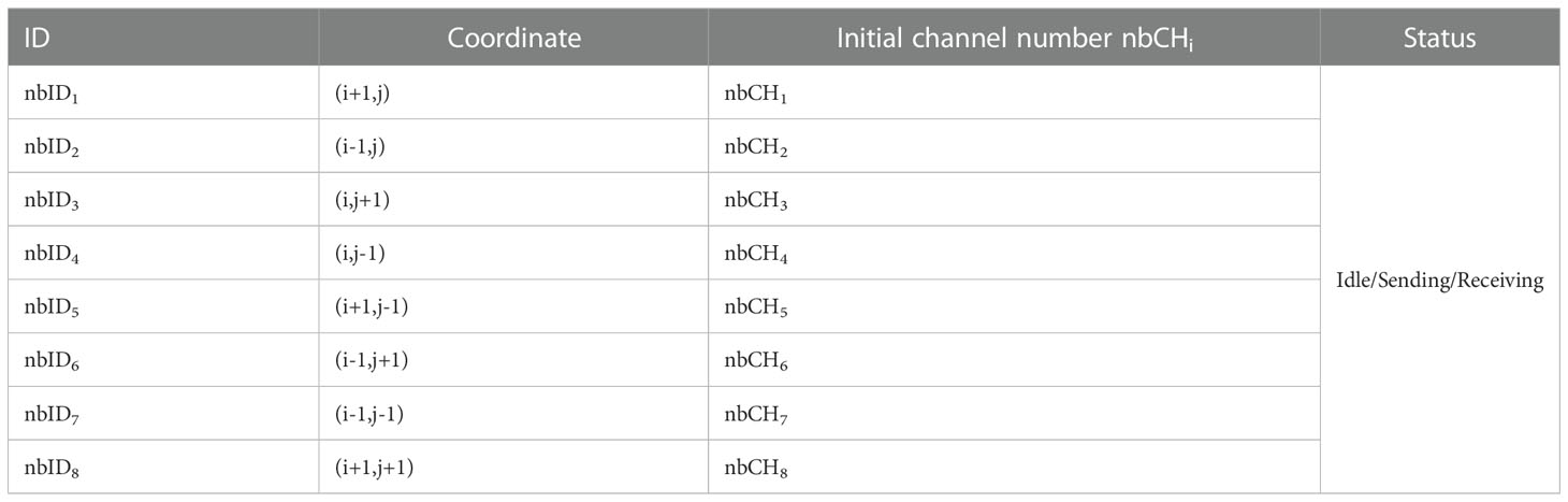
Table 1 Neighboring node list.
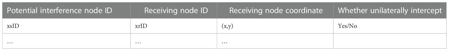
Table 2 Potential interference node list.
6. Performance evaluation
6.1. Simulation settings
According to the network model described in Section 4, the regular network simulation scenario is shown in Figure 8. The whole network is composed of 24 CHs and 1 Fusion Center (FC). CHs collect the data of each cluster sensor and send the data to the FC according to the path pointed by the arrows. The distance between CHs is 6km, and this distance is set to the one-hop transmission range between nodes. The network model is performed by the professional software OPNET for network simulations.
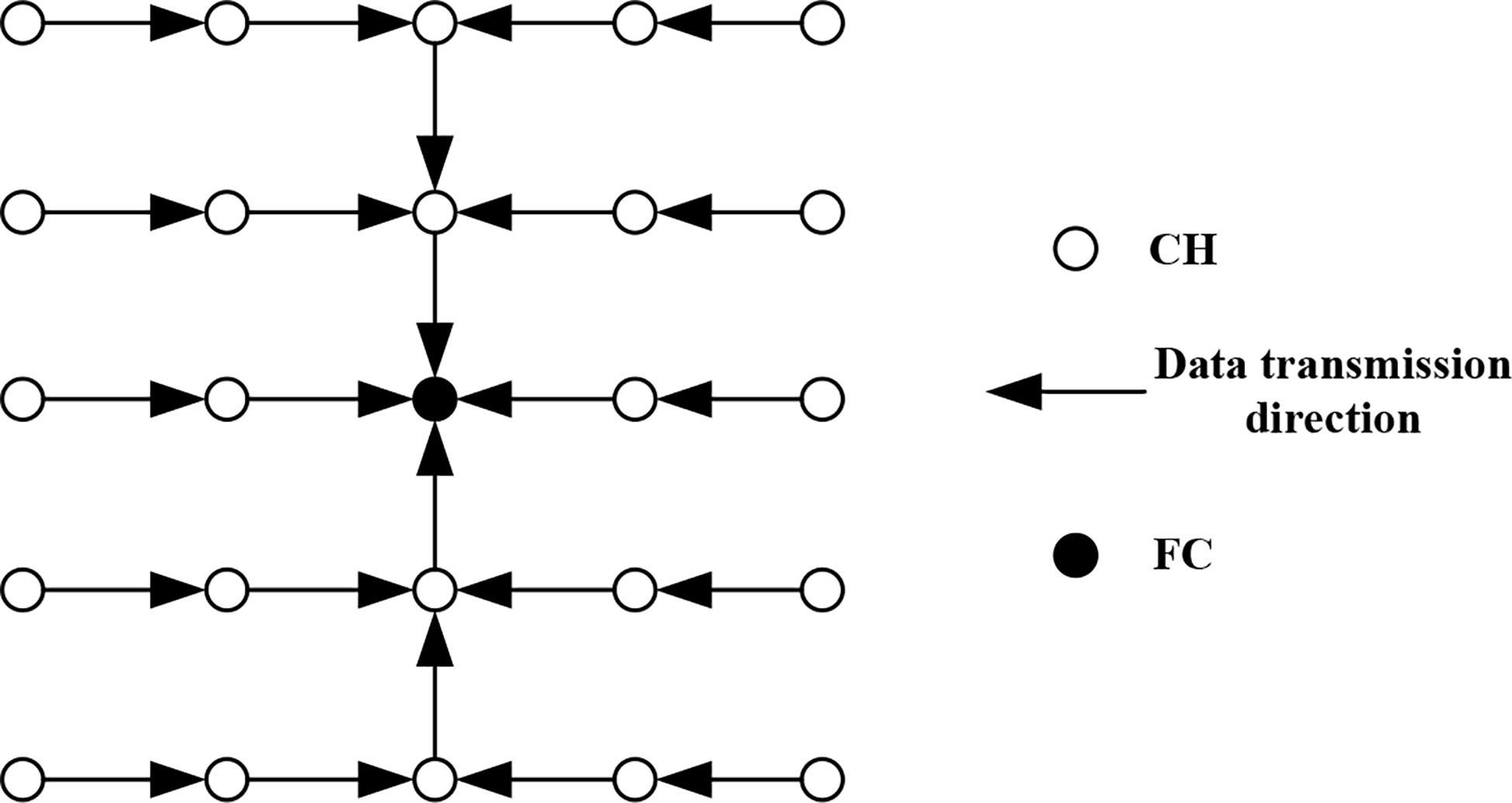
Figure 8 Network simulation scenario.
The other parameters are shown in Table 3. When the sending power is 33W, the SNR of the receiving node 6km away is 10dB.
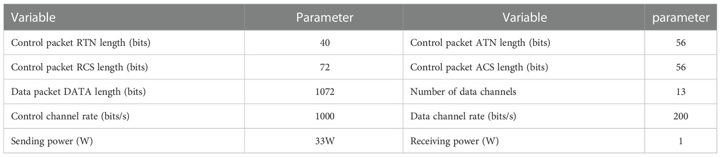
Table 3 Network simulation parameters.
6.2. Simulation results
6.2.1. Effectiveness and reliability of multichannel protocol under unsaturated status
Define packet arrival rate as the number generated by each frame, and this rate indicates the network traffic volume, denoted by the symbol “Packet Arrival Rate per Frame”. Define channel occupation rate as the ratio of actual transmission rate to channel volume, and this rate indicates the channel multiplexing capability in multi-hop environment, denoted by the symbol “Average Channel Occupancy per Frame”, revealing the effectiveness of the protocol in the network. The symbol “Data Successful Receiving Rate” represents the rate of successful data packet receiving, which is defined as the ratio of the number of successfully received data packets to that of data packets sent in the whole network, revealing the reliability of the protocol in the network. In the network application scenario in this study, the packet arrival rate of each CH is different. The nodes away from FC have small data amount waiting for transmission and, therefore, the packet arrival rate of them is relatively low, since these nodes do not need to retransmit data sent by CHs in last hop or only retransmit a few. Conversely, the packet arrival rate is relatively high. When the packet arrival rate is relatively low, not every CH has data to send in the frames of each slot, which is called the unsaturated status of a network. In Figure 9, “MulCh” represents the multichannel MAC protocol established in this study, while “SingleCh” represents single-channel MAC protocol.
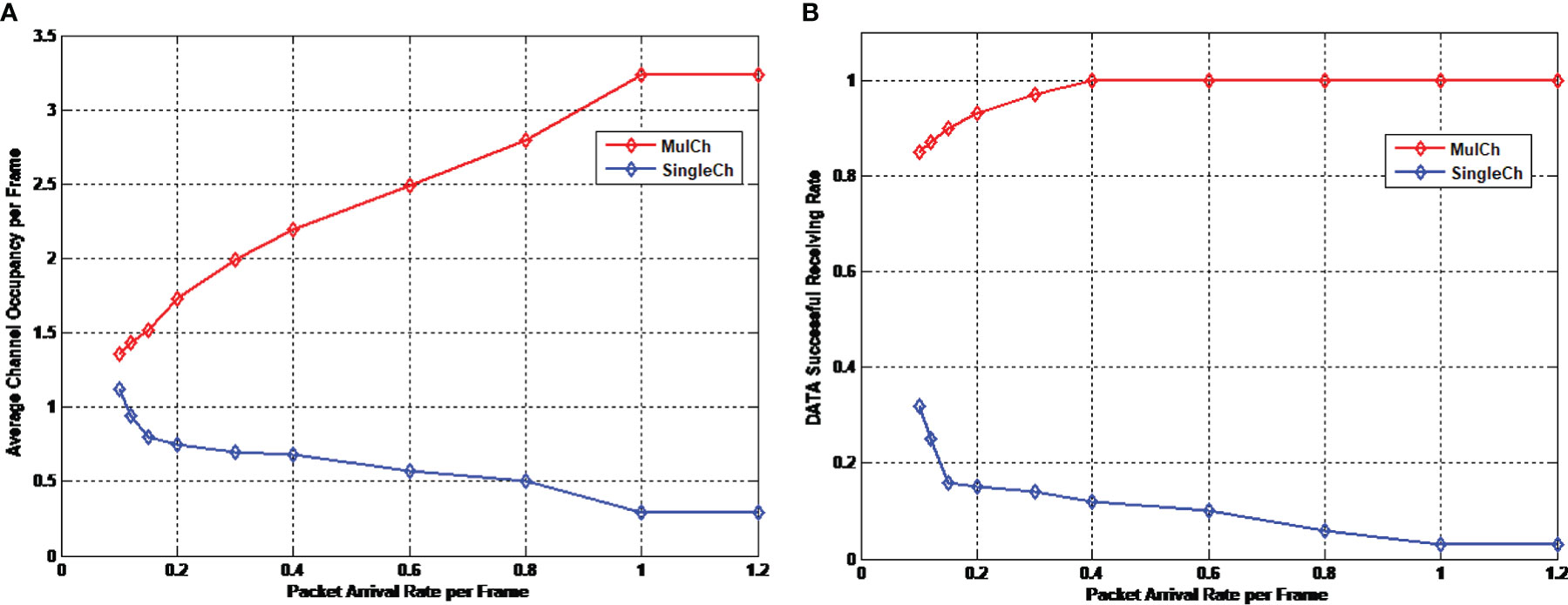
Figure 9 Effectiveness and reliability of multichannel protocol in unsaturated status. (A) Channel occupation rate (B) Successful data packet receiving rate.
It is clear in Figure 9A that with the increase of packet arrival rate, the channel occupation rate of the multichannel MAC protocol also increases. When the packet arrival rate reaches 1, all network nodes are in saturated status, and the channel occupation rate also tends to be saturated at this moment. It can be known from the previous demonstration that in underwater acoustic environment, the neighboring nodes of the single-channel MAC protocol,if they are out of one hop and within two hops, may interfere with the receiving of data packets. In this situation, even the collision avoidance negotiation of control packets cannot avoid the data packet collision between the neighboring nodes of single-channel MAC protocol. Therefore, when traffic volume is relatively small, the channel space multiplexing rate is relatively low. There are fewer data packet collisions, and the possibility of successful data packet receiving increases, showing relatively high channel occupation rate. Otherwise, when the traffic volume is relatively large, the control packet interaction within the traditional single-hop range is unable to avoid space multiplexing, so that the possibility of data packet collision increases, resulting in relatively low channel occupation rate. In comparison, the proposed multichannel MAC protocol uses the channel request packet within two-hop range to broadcast the channel utilization status of the current node, and adopts reasonable channel allocation algorithm to guarantee that no neighboring nodes within two-hop range can use the same data channel to send data packets, dramatically increasing the successful data packet receiving rate, and exhibiting relatively high channel occupation rate.
The successful data packet receiving rate in Figure 9B also verifies our analysis. In the figure, no matter what the packet arrival rate is, the successful data packet receiving rate of the multichannel protocol is over 80%. Moreover, with the increasing of packet arrival rate, all nodes in the network have data to transmit, instead of being limited to the CHs at FCs. Consequently, the transmission node pairs spread more sparsely, and the successful data packet receiving rate also increases. When the packet arrival rate reaches 0.4, it is possible to successfully receive all data packets sent.
6.2.2. Effectiveness of multichannel protocol in saturated status
In ideal channel allocation algorithms, a multichannel protocol does not change the channel occupation rate in the network due to the control packet collision in the transmission negotiation stage. This is because although the RTN packet and ATN packet collide in the transmission negotiation stage, the only result is that fewer nodes have channel selection request in channel selection stage. At this moment, directed by channel allocation algorithm, each transmission node pair obtains more channels for data transmission, and keeps the channel occupation rate unchanged. To verify the adaptability of the proposed channel allocation algorithm in the control of packet collision, a method is adopted in the simulation experiment in which the duration of transmission request sub-stage is reduced, so that the RTN packet collision is intensified. The variation of the average channel occupation rate under different RTN packet collisions is observed and shown in Figure 10. In the figure, the horizontal axis represents the number of time slots when sending RTN packets in the transmission request sub-stage, denoted by the symbol “RTN Slots”. The longer the time of control packet interaction is, the more the allocable slots will be; and the fewer the time slots are, the larger the possibility of RTN packet collision is. In Figure 10A, the symbol “RTN Successful Receiving Rate” represents the successful RTN packet receiving rate. In Figure 10B, the symbols “Mulch @Saturation” and “Single @Saturation” represent the performance of multichannel protocol and single channel protocol under saturated status, respectively. “Mulch@up” and “Single@down” represent the upper boundary of multichannel protocol performance and the lower boundary of single channel protocol performance, respectively.
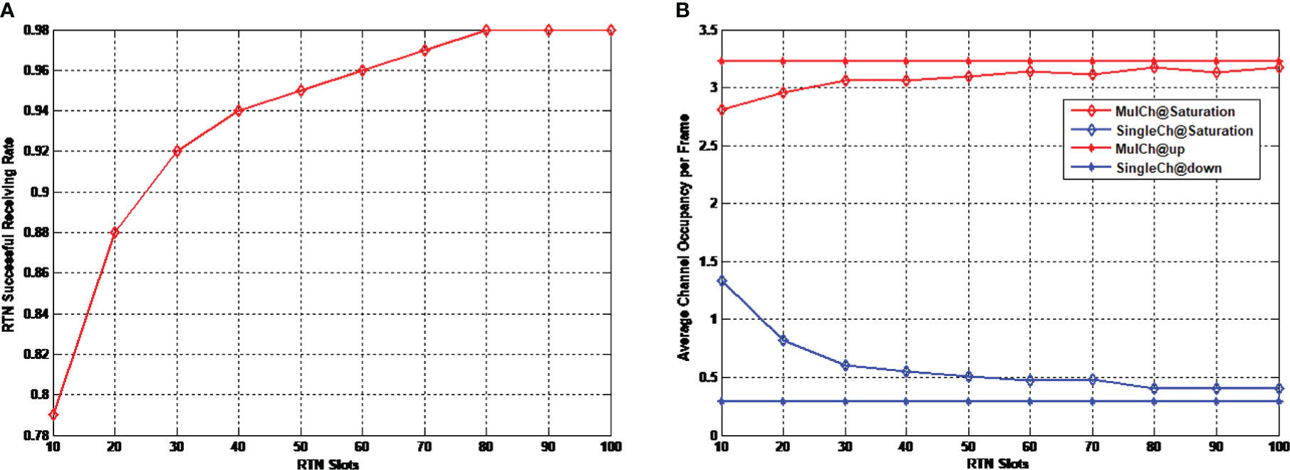
Figure 10 Effectiveness of multichannel protocol under saturated status. (A) Successful RTN packet receiving rate (B) Average channel occupation rate.
It is clear in the figure that with the increase of the RTN slots, the successful RTN packet receiving rate increases, and so does the channel occupation rate of the multichannel protocol, approaching the channel occupation rate in ideal situation. The performance curve shows a relatively flat shape, which demonstrates that the channel allocation algorithm can relatively well adapt to the control packet collision, and does not dramatically reduce the channel occupation rate due to the control packet collision. The channel occupation rate of the single-channel protocol decreases with the increase of successful control packet receiving rate. This is because the more the transmission node pairs are, the higher the possibility that the data packets are interfered with is, and the lower the successful receiving rate will be. When there is no collision of control packets, the channel occupation rate approaches the lower bound of performance.
6.2.3. Energy efficiency
The energy consumption in the network includes the energy consumed by control packet sending and receiving as well as that consumed by data packet sending and receiving. We define average energy consumption per bit as the ratio of the total energy consumption to the number of successful received bits, with Joule being its unit, denoted as “Average Energy Consumption per Bit” in Figure 11. And also we define energy efficiency as the ratio of the energy consumption of successful data packet transmission to the total energy consumption, denoted as “Energy Efficiency”. The higher the energy efficiency is, the smaller the extra cost brought by data packet collision or control packet interaction will be. “MulCh” and “SingleCh” represent the performance of multichannel protocol and single-channel protocol, respectively. “MulCh @up” and “SingleCh @up” represent the performance’s upper bounds of multichannel protocol and single-channle protocol, respectively. Note that they are the performance in ideal status, which means there is no any cost spent.
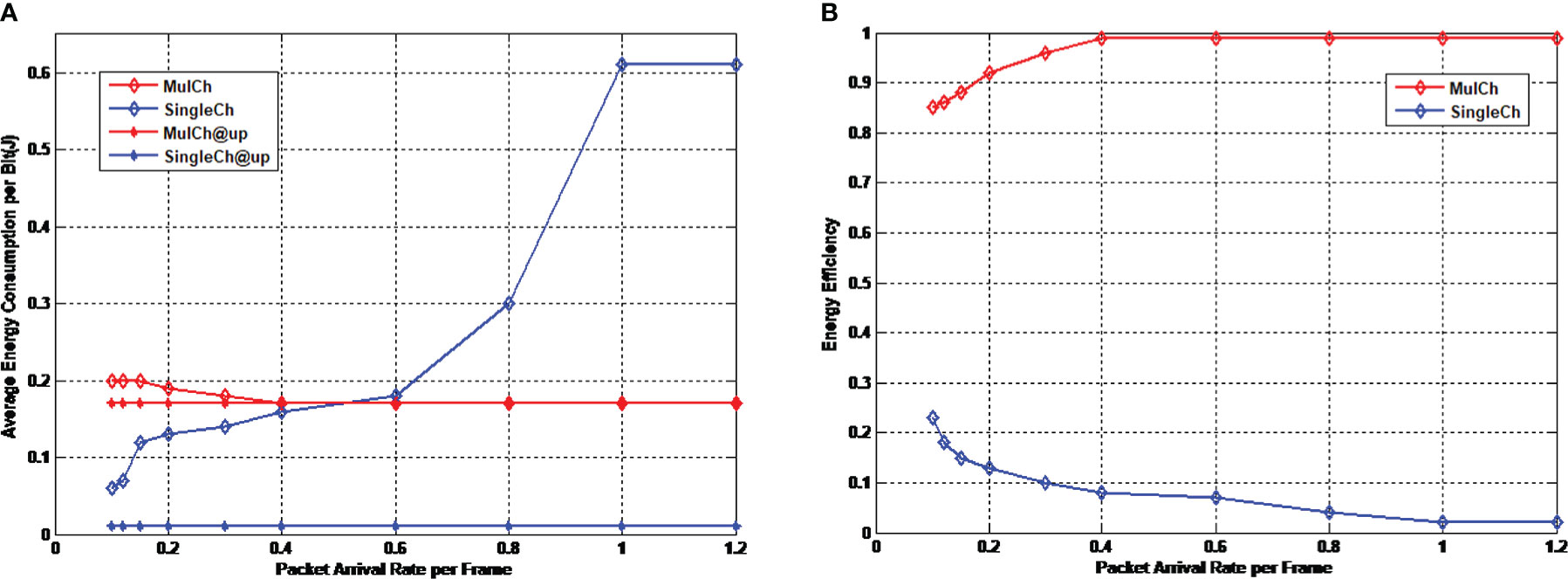
Figure 11 Energy efficiency of multichannel protocol. (A) Average energy consumption per bit (B) Energy efficiency.
It is clear in Figure 11A that since the data transmission rate of the multichannel protocol is much lower than that of the single-channel protocol (the ratio in this protocol is 1 to 13). Therefore, the energy consumption per bit of the single-channel protocol in ideal status is much lower. However with the increase of packet arrival rate, the energy consumption per bit of the multichannel protocol tends to be stable, and approaches to the energy consumption in ideal status. In comparison, the energy consumption per bit of the single-channel protocol increases with the increase of packet arrival rate. Moreover, when the packet arrival rate is larger than 0.6, the energy consumption of single-channel protocol exceeds that of multichannel protocol. From the aspect of energy efficiency shown in Figure 11B, the energy efficiency of the multichannel protocol is significantly better than the single-channel protocol in which more energy is consumed by extra costs (including data packet collision and control packet interaction), demonstrating the high reliability of the multichannel protocol.
It can be concluded that compared with single-channel protocol, the multichannel protocol designed in this study has relatively high channel occupation rate and successful data packet receiving rate under different traffic volumes. Moreover, the proposed multichannel protocol is adapted to control packet collision, and the channel occupation rate approaches the ideal value, demonstrating that the designed channel allocation algorithm can not only avoid collisions, but also utilize all usable channels. Although the increase of channels reduces the data transmission rate and the theoretical energy consumption per bit is much higher than that of single-channel protocol, the increase of successful data packet receiving rate could compensate the energy consumption caused by the data transmission delay
7. Conclusion
In this study, aiming at the multichannel hidden terminal problem and long propagation delay hidden terminal problem in the multichannel MAC protocol design for long-delay UASNs, a multichannel MAC protocol GCMAC is proposed based on graph coloring theory, which is adapted to distributed underwater acoustic network environment. The GCMAC protocol adopts a synchronized work method. It performs negotiation and channel selection before data transmission, and then determines the transmission node pairs and channels to be used. It selects as may idle channels as possible for each transmission node pair based on coloring theory. Simulation results show that the proposed multichannel MAC protocol has relatively high channel occupation rate and successful data packet receiving rate, as well as much higher energy efficiency compared with single-channel MAC protocol.
Data availability statement
The original contributions presented in the study are included in the article/supplementary material. Further inquiries can be directed to the corresponding author.
Author contributions
YW and DW contributed to conception and design of the study. DW organized the database. YW performed the statistical analysis. DW wrote the first draft of the manuscript. YW wrote sections of the manuscript. All authors contributed to manuscript revision, read, and approved the submitted version.
Funding
This work was supported by the National Natural Science Foundation of China (Grant No. 62271427).
Acknowledgments
The authors would like to thank the support from the teachers and students in the Underwater Acoustic Communication Lab of Xiamen University.
Conflict of interest
The authors declare that the research was conducted in the absence of any commercial or financial relationships that could be construed as a potential conflict of interest.
Publisher’s note
All claims expressed in this article are solely those of the authors and do not necessarily represent those of their affiliated organizations, or those of the publisher, the editors and the reviewers. Any product that may be evaluated in this article, or claim that may be made by its manufacturer, is not guaranteed or endorsed by the publisher.
References
Alfouzan F. A., Shahrabi A., Ghoreyshi S. M., Boutaleb T. (2019). A collision-free graph coloring MAC protocol for underwater sensor networks. IEEE Access 7, 39862–39878. doi: 10.1109/ACCESS.2019.2906555
Ansari S., Poncela Gonzalez J., Otero P., Ansari A. (2015). Analysis of MAC strategies for underwater applications. Wireless personal communications: An Int J. doi: 10.1007/s11277-015-2743-1
Bouabdallah F., Zidi C., Boutaba R., Mehaoua A. (2017). Collision avoidance energy efficient multi-channel MAC protocol for UnderWater acoustic sensor networks. IEEE Trans. Mobile Comput. 18 (10), 2298–2314. doi: 10.1109/TMC.2018.2871686
Chang G. J., Kuo D. (1996). The L(2,1)-labeling problem on graphs. SIAM J. Discrete Math. 9 (2), 309–316. doi: 10.1137/S0895480193245339
Chao C., Lu M., Lin Y. (2015). Energy-efficient multichannel MAC protocol design for bursty data traffic in underwater sensor networks. IEEE J. Ocean. Eng. 40 (2), 269–276. doi: 10.1109/JOE.2014.2304311
Chen K.C.K., Ma M.M.M., Cheng E.C.E., Yuan F.Y.F., Su W.S.W. (2014). A survey on MAC protocols for underwater wireless sensor networks. IEEE Communications surveys and tutorials 16, 3, 1433–1447. doi: 10.1109/SURV.2014.013014.00032
Cui J., Kong J., Gerla M., Zhou S. (2006). The challenges of building scalable mobile underwater wireless sensor networks for aquatic applications. IEEE Netw. 20 (3), 12–18. doi: 10.1109/MNET.2006.1637927
Fitzpatrick S.S.U.C., Janssen J.J.M.D., Nowakowski R.R.M.D. (2004). Distributive online channel assignment for hexagonal cellular networks with constraints. Discrete Appl. Math. 143 (1-3), 84–91. doi: 10.1016/j.dam.2003.06.005
Hsu C., Lai K., Chou C., Lin K. C. (2009). ST-MAC: Spatial-temporal MAC scheduling for underwater sensor networks (Rio de Janeiro, Brazil: Institute of Electrical and Electronics Engineers Inc), 1827–1835.
Huang J., Wang H., He C., Zhang Q., Jing L. (2018). Underwater acoustic communication and the general performance evaluation criteria. Front. Inf. Technol. electron. Eng. 19 (8), 951–971. doi: 10.1631/FITEE.1700775
Jahanbakht M., Xiang W., Hanzo L., Rahimi Azghadi M. (2021). Internet Of underwater things and big marine dataanalytics: A comprehensive survey. IEEE Commun. Surv. Tut. 23 (2), 904–956. doi: 10.1109/COMST.2021.3053118
Jiang S. (2018). State-of-the-Art medium access control (MAC) protocols for underwater acoustic networks: A survey based on a MAC reference model. IEEE Commun. Surveys Tutorials 20 (1), 96–131. doi: 10.1109/COMST.2017.2768802
Kuhn F., Wattenhofer R. (2006). On the complexity of distributed graph coloring (Denver, CO, United states: Association for Computing Machinery), 7–15.
Ramanathan S., Engineer I.O.E.A (1997). “A unified framework and algorithm for (T/F/C)DMA channel assignment in wireless networks,” in INFOCOM '97. Sixteenth Annual Joint Conference of the IEEE Computer and Communications Societies. Driving the Information Revolution., Proceedings IEEE. 900–907.
Rhee I., Warrier A., Min J., Xu L. (2009). DRAND: Distributed randomized TDMA scheduling for wireless ad hoc networks. IEEE Trans. Mobile Comput. 8 (10), 1384–1396. doi: 10.1109/TMC.2009.59
Saifullah A., Xu Y., Lu C., Chen Y. (2014). Distributed channel allocation protocols for wireless sensor networks. IEEE Trans. Parallel Distributed Syst. 25 (9), 2264–2274. doi: 10.1109/TPDS.2013.185
So J., Vaidya N. (2004). Multi-channel MAC for ad hoc networks: Handling multi-channel hidden terminals using a single transceiver (Tokyo, Japan: Association for Computing Machinery). 222–233. doi: 10.1145/989459.989487
Wang W., Liu X. (2005). List-coloring based channel allocation for open-spectrum wireless networks (Dallas, TX, United states: Institute of Electrical and Electronics Engineers Inc), 690–694. doi: 10.1109/VETECF.2005.1558001
Keywords: underwater acoustic sensor networks, multichannel, medium access control, graph coloring, system throughput, energy efficiency
Citation: Wei Y and Wang D (2023) Graph coloring-based multichannel MAC protocol in distributed underwater acoustic sensor networks. Front. Mar. Sci. 9:1005959. doi: 10.3389/fmars.2022.1005959
Received: 28 July 2022; Accepted: 23 December 2022;
Published: 18 January 2023.
Edited by:
Haixin Sun, Xiamen University, ChinaReviewed by:
Arun Prakash, Motilal Nehru National Institute of Technology Allahabad, IndiaKai Liu, Beijing Institute of Technology, China
Copyright © 2023 Wei and Wang. This is an open-access article distributed under the terms of the Creative Commons Attribution License (CC BY). The use, distribution or reproduction in other forums is permitted, provided the original author(s) and the copyright owner(s) are credited and that the original publication in this journal is cited, in accordance with accepted academic practice. No use, distribution or reproduction is permitted which does not comply with these terms.
*Correspondence: Yunlong Wei, d2VpeXVubG9uZ0BmenUuZWR1LmNu