- 1Laser Enabled Manufacturing Group, Photonics, Council for Scientific and Industrial Research, Pretoria, South Africa
- 2Department of Mechanical and Mechatronics Engineering, Faculty of Engineering and the Built Environment, Tshwane University of Technology, Pretoria, South Africa
This study investigates the spheroidization of titanium Ti-6Al-4V powder particles using numerical models developed in Abaqus and OpenFOAM. Spherical particles are crucial in powder-based additive manufacturing due to their superior flowability, packing density, and mechanical properties, enhancing printing precision and the quality of final products. While conventional techniques such as gas atomization and plasma spheroidization have been extensively researched, the potential of laser spheroidization remains underexplored. To address this gap, detailed numerical analyses of laser spheroidization were conducted, modeling heat transfer from the laser to powder particles using a transient uncoupled heat transfer method with latent heat considerations, while particle deformation was simulated with a phase-fraction-based interface-capturing approach integrated with Navier-Stokes equations. The results, validated against analytical models, indicate that particles within the 20–80 μm range experience optimal spheroidization within a 0.005-second residence time under laser heating, with particles smaller than 30 μm reaching evaporation temperatures of 5,000°C, while larger particles reshape without evaporating under a typical heat flux of 94 MW/m2 (1.8 kW laser power). This study demonstrates that laser spheroidization of Ti-6Al-4V powder can potentially increase powder yield by 10%, offering higher power density and shorter melting times compared to plasma spheroidization, thus presenting a more efficient alternative for achieving spherical particles of specific sizes.
1 Introduction
Spherical titanium (Ti) alloy powder is used extensively in additive manufacturing (AM), powder injection molding, and powder metallurgy (PM) processes. However, the widespread use of PM and AM Ti is limited by the prohibitively expensive cost of Ti powder, particularly in its spherical alloy form. As a result of its superior flowability, packing density, and sinterability, spherical titanium powder is becoming more and more in demand as powder-bed-based AM technologies gain traction. This trend emphasizes the crucial role that spherical shape plays in enhancing additive manufacturing processes and final part quality, redefining the value of both features and cost in powder production operations. The lack of competitively priced, high-quality spherical metal powders continues to be an important barrier to the growth of AM technology, contributing to a lack of alternative methods for spheroidization.
Other, critical features of spherical powder include particle size, flowability, and chemical compositions, particularly oxygen concentration (Sun et al., 2017). The value chain analysis of titanium spheroidization has an enormous gap, especially when it comes to low-cost ways to make high-grade spherical powders (Nkhasi et al., 2023; Nkhasi et al., 2021). The cost and scalability of existing methods like as mechanical alloying, gas atomization, and plasma spheroidization are constrained. The lack of systematic comparison studies makes it difficult to optimize these procedures. We are investigating laser-based spheroidization as a potential solution to close this gap and create a scalable and more effective process.
Several commercial procedures, including gas atomization (GA), plasma atomization (PA), plasma spheroidization (PS), and the plasma rotating electrode procedure (PREP), have been used to produce spherical Ti powders (Sun et al., 2017; Ahmad et al., 2023; Anderson, 2010; Blank et al., 2023; Buttsworth, 2001). Each process includes melting, atomization, and solidification. While Particle size distribution (PSD) can be controlled using GA, cost-effective AM applications are hindered by its low fine powder production. However, PREP offers benefits including less satellite particles and excellent purity, but its coarser particle size range and manufacturing rate are constrained. Nonetheless, powders in the powder range of 10–300 µm were generated by GA techniques (Sun et al., 2017; Popov et al., 2021; Yanko et al., 2020).
The PREP is an improvement of the rotating electrode process (REP) that provides benefits such as high purity, small gas pores, and fewer satellite particles. This method replaces a bar with a spinning wire as the metal supply, producing excellent purity, reasonably spherical particles, and small particle sizes. However, according to Yanko et al. (2020), the process has a low production rate, a high level of purity, a high-quality form, and no satellites. In addition, the normal particle size range is coarser (50–350 μm), which restricts its applicability for several situations (Sun et al., 2017). The wire is utilized in the PA process, which involves melting Ti wire or powder using plasma torches, and then solidifying the molten droplets into spheres of powder. The PA is an appropriate method for AM because of its low satellite count, high production rate, high purity, and enhanced yield of fine powder, but it still has issues with satellite particles and interior porosity. However, using this technology to prepare powder results in extraordinarily high costs. To create a spherical powder that outperforms the competition in terms of the quantity of spherical powder particles produced, is less expensive, and has a high level of purity, PS is a new plasma-based technique that involves melting Ti powder using plasma torches.
In terms of spheroidization modeling, it is crucial to explore the utilization of various numerical techniques to model fluid interfaces within a computational framework such as free surface boundaries since the spheroidization of powder involves melting and solidifying the material in a gaseous atmosphere. In contrast to computational studies for spheroidizing and atomization processes, there are many more experimental results (Guildenbecher et al., 2009; Ping et al., 2010; Bao et al., 2021; Li and Ishigaki, 2004; Guo et al., 2023; Huang et al., 2023) in the literature compared to simulation. There are few numerical approaches that have been developed. Nonetheless, very few studies have been conducted on phase transition in a two-phase flow of two unique immobile fluids. According to Elgeti and Saucerland (2016), the majority of proposed and successful methods are based on the use of an Eulerian grid covering the entire domain (possibly including various fluids), where the fluid-flow equations are solved and coupled with an appropriate method to capture or track the interface, such as the level-set method, the volume-of-fluid method, particle methods, and the phase-field method (Scheufler and Roenby, 2021). This would be suitable for capturing the interface when the particles have been melted.
Fewer techniques, like smoothed particle hydrodynamics (SPH) and finite element methods (FEM), rely on the Lagrangian tracking of fluid elements. Originally designed to solve dynamical problems, SPH is a fully Lagrangian mesh-free technique that has been successfully used for a number of fluid-dynamic systems. Colagrossi and Landrini (2003), for example, used SPH to study and simulate two-dimensional interface flows with low density ratios. They found that their SPH implementation was stable and able to handle a variety of air-water flow scenarios, such as air entrapment and interface breaking. To be more precise, they designed a density re-initialization process to increase mass-area-density consistency and filter out small-scale pressure oscillations and introduced interaction terms to maintain algorithm stability for tiny density ratios. Blank et al. (2023), on the other hand, develops a unique method for simulating surface tension effects using SPH. In order to effectively simulate free surface events, the Young–Laplace pressure boundary condition is a crucial component that the research incorporated into their surface tension model. The study’s results were encouraging, showing that the suggested model may successfully and very accurately anticipate droplet behaviour and surface tension effects by integrating this boundary condition into SPH particles near free surfaces. Nonetheless, a number of test scenarios are used to validate the model. Interestingly, simulations of Rayleigh-Plateau instability and droplet equilibrium pressure show great accuracy, with relative errors as low as 2.5% when compared to analytical predictions. Additional verification using droplet oscillations and spherical droplet coalescence tests demonstrates the stability and robustness of the model in representing intricate fluid dynamics processes.
Similar to this, Cosimo et al. (2013) used FEM to investigate a novel, enriched finite element method for isothermal phase change problems. The methodology showed superior accuracy over traditional formulations without spurious oscillations. This fixed mesh methodology, in contrast to conventional approaches, uses enriched finite element spaces to describe discontinuities in temperature gradients without depending on auxiliary schemes such as level sets. It also handled a straightforward titanium alloy welding challenge with success. Their work focused on accurately capturing the behavior of fluid interfaces, which are often complex and challenging to model with traditional methods. In addition, the boundary element (BEM), the FEM approach, and the finite difference method (FDM) are further numerical techniques for resolving the governing equations of the phase change process (Reddy et al., 2023). The FDM, FEM, and Finite Volume Method (FVM) are the three main numerical techniques that are frequently employed in CFD. Using the FDM method, Harlow and Welch (1967) investigated the behavior of fluid flow with a free surface, paying special attention to the fluid’s motion when subjected to surface tension and gravity. Zhang et al. (2008) used the FDM to simulate thermal deformation in a three-dimensional thin film exposed to ultrashort pulsed lasers. The technique specifically seeks to prevent non-physical oscillations in the solution and precisely simulate thermal deformation. The study’s conclusions show how well the established numerical method works for analyzing changes in stress and displacement in thin films exposed to ultrashort pulsed laser light. The thermal deformation process can be better understood by examining the numerical results that show expansion in specific directions within the center region of the thin film. But according to Yu et al. (2010), who developed and implemented some BEM variants, stated that the FDM is based on a finite difference approximation for governing differential equations using grid uniformly spaced nodes; this means that it needs very fine grids and domain meshes, which means that it is not appropriate for infinite problems. It lengthens the computation process.
There is commercial software available such as ABAQUS, COMSOL, and ANSYS, that uses FEM to solve heat transport problems including phase transition. Extensions have been put into place, though, including the user subroutine HETVAL in Abaqus to add phase transitions (Abaqus, 2011), variational multiscale formulations when the method is used for fluid flow, and proper orthogonal decomposition (POD) (Xielin et al., 2021). The enriched finite element formulations employ the shape function and the consecutive-interpolation process (CIP) (Cosimo et al., 2013). The authors reported that these strategies are challenging to implement and require numerous stabilizing measures (Rasthofer et al., 2011). Furthermore, a number of authors have combined FEM and BEM to investigate steady-state 2D heat transmission problems for structures with multi-scale features (Qin et al., 2022; He et al., 1995; Ji et al., 2020; Hsiao et al., 1999). Nevertheless, there are only a few literature reviews on this combination. Furthermore, two benefits of using a linked system are the Abaqus post-disposal features and the capacity to tackle infinite problems (Qin et al., 2022).
There are few studies conducted on using the extended finite element method (XFEM) as a prediction tool when modeling two-phase flow or element discontinuity, because of its capacity to evaluate without meshing, various authors employed this method to analyze discontinuity crack problems or dynamic fracture problems on material (Bybordiani et al., 2021; Khoei, 2014). Their results show that it can effectively capture material deformation. These results point to the possibility of more precise and effective simulations of material failure processes using the suggested local formulation of XFEM. For multi-field thermo-hydro-mechanical issues in a discontinuous porous medium (fluid flow in porous media), Ahmad et al. (2023) employed XFEM in COMSOL. It was mentioned that this approach employs the nodal shape and enrichment state functions, both of which prevent remeshing. However, this approach is challenging to put into practice and calls for both stabilization strategies and social integration routines. CFD, which predicts fluid flow using conservation laws, is one of the disciplines of fluid mechanics that forecast fluid flow. The Navier-Stokes equation, which is based on modern CFD, was created after viscous transport was added to the Euler equations by Claude-Louis Navier and George Gabriel Stokes (Anderson, 2010). However, according to a study by Celik et al. (2021), While DEM and CFD can be used to anticipate the behaviours of solid flows, they can also be used to compute metal flow. The CFD accurately describes the phase transition by accounting for temperature variations. Physical transition and turbulence modelling are still being worked on, according to Spalart and Venkatakrishnan (2016). Current CFD mostly uses the FEM and FVM rather than the FDM since they provide discrete solutions while the FEM provides continuous (up to a point) solutions. Jeong and Seong (2014) found that FEM codes are more influenced by the type and quality of the mesh than FVM CFD programmes (Ansys, CFX, and Fluent) after simulating flow phenomena in a range of sectors. It was found that the FVM code required significantly less computing time when compared to the FEM code. For AM and PM technologies to evolve, high-quality, reasonably priced spherical titanium powder production is essential. Although the existing approaches have many benefits and drawbacks, there is a great deal of room for advancement through sophisticated modeling strategies and creative spheroidization procedures. Ti powders’ full potential in industrial applications will need to be realized, which will require addressing the scalability and affordability issues. The lack of numerical modeling research has resulted in a significant gap in the systematic comparison and optimization of current spheroidization techniques.
This study investigates the potential feasibility of laser-based spheroidization, a technique that, while gaining attention in some industries, has not been extensively researched compared to traditional materials processing methods. One notable distinction is that previous research on traditional methods, such as gas atomization and plasma spheroidization, has largely relied on experimental approaches, with little to no use of advanced simulations. This gap underscores the novelty of our approach, which combines simulations in both Finite Element Analysis (FEA) for heat transfer using Abaqus and Computational Fluid Dynamics (CFD) for surface tension effects using OpenFOAM. Our research focuses on understanding the deformation behavior of titanium powder when exposed to laser energy, aiming to determine whether this method can serve as a feasible and efficient alternative to current spheroidization techniques. As laser-based methods mature and the necessary equipment becomes more widely available, we anticipate increased research and development efforts in this area. The study is structured as follows: Section 3 introduces the governing equations, Section 4 presents the results from our simulations, and Section 5 concludes with an analysis of our findings and their implications.
2 Mathematical models
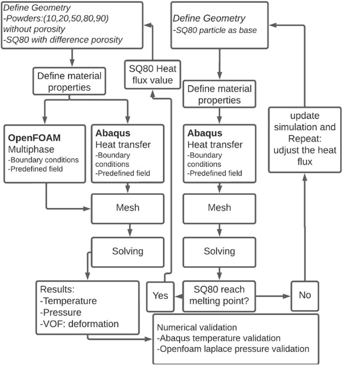
The current study employs a comprehensive approach to evaluate the heat transfer and deformation properties of powder particles using two advanced simulation tools: Abaqus and OpenFOAM. As illustrated in Figure 1, Abaqus was employed to assess heat transfer parameters for powder particles within the size range of 20–80 μm, similar to the Particle Size (PS) range referenced in Slotwinski et al. (2014), Wahll et al. (1961) and Samokhin et al. (2019). OpenFOAM was used to analyze the deformation behavior of these particles during the melting phase. The study begins with the creation of particle models in CAD software, followed by defining material properties specific to the powder particles. The meshing process includes a rigorous mesh independence analysis and quality verification to ensure accuracy. Critical thermal data is provided via heat transfer simulations in Abaqus using the Gaussian heat flow implemented by the DFLUX subroutine, which are then used as input for deformation simulations in OpenFOAM. Figure 1 presents a flowchart detailing the sequential steps involved in both simulations, encompassing modeling, meshing, heat transfer analysis, and deformation simulations. The results from these simulations were evaluated to gain insights into the thermal and deformation responses of the powder particles.
2.1 Heat transfer model
In this study, heat transfer modeling and fluid modeling are the two main categories of simulation. The heat transfer analysis was conducted using Abaqus/CAE 6.14, focusing on the heat transfer from the laser beam to a solid titanium powder particle. The analysis included considerations for convection and radiation boundary conditions. OpenFOAM-v2306 was utilized to study the deformation of titanium powder particles in the liquid phase due to Abaqus’ limitations in accessing certain features and the challenges in developing specific subroutines. Table 1 summarizes the parameters used in defining the material model. Figure 3A outlines the laser-based spheroidization process, where powder particles are vibrated out of a hopper to reduce their flight speed and then pass through a horizontally positioned laser beam that heats and melts them. Post heat exposure, the particles solidify, completing the spheroidization process.

Table 1. Temperature-dependent material properties of Ti-6AI-4V and Air (Lu et al., 2019; Mills, 2002; Gereltbyamba and Lee, 2018).
2.1.1 Heat transfer governing equations
The governing equations for heat transfer in the study is given by Equation 1 (Abaqus, 2011; Buttsworth, 2001):
where
The initial condition for all materials is defined in Equation 2, and the temperature
where
where
In this equation,
where P is the laser power in W, r0 is the radius of the Gaussian laser beam and r is the radial distance in m. In a Gaussian form, the concentration of the heat flux is at the center, and moving away from the center sees a decrease in heat flux. Equation 1 is transformed into Equation 8:
2.1.2 Model implementation and solution approach
This was performed at a period of 0.005 s for 3D transient heat transfer problems in an isotropic medium. In order to identify appropriate meshing, a grid refinement research was conducted using the SQ80 powder particle as a reference. Based on the findings, the powder particle was finally meshed with 3,268 8-node linear heat transfer brick components (DC3D8) with a global seed size of 0.002 mm for heat transfer studies.
2.1.2.1 Initial and boundary conditions
The initial thermal conditions were established by setting the temperature throughout the domain 20°C. To facilitate the simulation, a time step size of 0.005 s was chosen. The determination of the appropriate heat flux for the Neumann boundary condition (heat flux) was accomplished through an iterative methodology involving multiple simulation runs and adjustments in order to determine the optimal laser power for heating SQ80, SQ50, and SQ20 powder particles within the desired timeframe. Taking into account differences in particle size and simulation length for SQ80, SQ50, and SQ20 particles, this approach was crucial to guaranteeing that the intended melting behavior was generated within the powder particle bath. SQ80 particles were used was used as reference, specifically to determine whether the melting temperature was reached. This was achieved by varying the laser strength in the DFLUX subroutine until the melting point was reached by the larger particle (SQ80) at the specified time. Even though the process of trial and error made it easier to determine the ideal heat flux, more validation and improvement were still required. The impact of convection and radiation was deemed important (Ökten and Biyikoğlu, 2021; Mishra and Kumar, 2019; Romano et al., 2015). This choice is founded on the notion that differences in convection and radiation can have significant consequences, thus they cannot be ignored within the scope of the present study.
To account for heat losses, a surface film condition and surface radiation were applied to all exposed surfaces, with the exception of the surface where the heat flux was applied (see Figures 6A, 5). Abaqus models heat losses using a film coefficient
where
where
The emissivity is taken as a constant of 0.65. The chosen emissivity is based on the fact that radiative loss dominates overall heat losses at high temperatures, as demonstrated by Romano et al. (2015) in their study, which found that the overall emissivity of Ti-6Al-4V at high temperatures is around 0.65.
2.1.2.2 Geometry and mesh
In the simulation study using Abaqus/CAE, heat transfer analysis was conducted to model the behavior of SQ80, SQ50, and SQ20 powder particles. These particles were represented by cubes with side lengths of 64 μm, 39.8 µm, and 15.6 µm, respectively. The choice of using cubic shapes was deliberate to reduce computational cost and complications, as it simplifies the mesh generation and calculation processes compared to more complex geometries. Each powder particle was subjected to heat transfer conditions to replicate the thermal behavior as described in the literature. Additionally, the simulation considered the porosity of the powder particles by introducing void cubes within the SQ80Pore, SQ50Pore, and SQ20Pore particles. The side lengths of these void cubes were 32 μm, 12 μm, and 8 μm, respectively.
To ensure a comprehensive analysis, powder sizes outside the specified range were also considered, including SQ90 with a side length of 72 µm and SQ10 with a side length of 8 µm. For the SQ80 particles, different porosity sizes were further simulated with void cube side lengths of 0.048 mm, 32 μm, and 16 µm to elaborate the effect of porosity. This detailed consideration of both the particle and void dimensions, as well as the additional sizes, allowed for a thorough analysis of heat transfer and thermal conduction within the powder bed, ensuring the simulation accurately represented the conditions described in the literature.
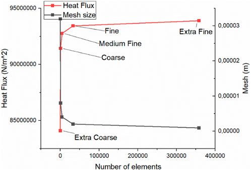
To predict results with accuracy, precise simulation outcomes are imperative. Therefore, a mesh convergence study was conducted to refine the mesh density and improve the accuracy of the simulation, as show in Figure 2. The SQ80 powder particle underwent a grid refinement study to determine proper meshing. Based on the findings, the powder particle was finally meshed with 32,768 8-node linear heat transfer brick components (DC3D8) with a global seed size of 0.2 µm for heat transfer studies which is within fine and extra fine mesh. Furthermore, since smaller powder particles than SQ80 were involved, the mesh size had to be reduced proportionally when meshing the smaller powder particles by the same size ratio to maintain accuracy and consistency across the simulation. This ensured that all powder particles were adequately represented within the simulation environment, facilitating a comprehensive understanding of their thermal behavior.
2.2 Assumptions
Due to the complexity of associated simulations in simulating powder particle melting, the current model incorporates the following assumptions and simplifications to streamline the solution and make it more suitable for actual casting conditions:
• The influence of phase change in terms of evaporation is not considered.
• The powder particle is considered stationary while the laser is moving.
2.3 Multiphase governing equations
This section describes the approach used to simulate molten titanium in flight mode using the InterFOAM solver in OpenFOAM (OpenCFD, 2023). The simulation focuses on the behavior of molten titanium in air while accounting for gravity and surface tension. The InterFOAM solver was chosen due to its ability to handle multiphase flows with phase interaction. The simulation considered the fluid properties (density, viscosity, and surface tension) of titanium for both nonporous and porous powder particles immersed in air at constant pressure and ambient temperature. CFD is an important branch of fluid dynamics that uses numerical techniques to address issues with fluid flow that are governed by The Navier-Stokes equations, which govern fluid flow, are shown in Equation 12:
Where
The constant-density continuity equation is represented by Equation 13:
where
The mass conservation of the liquid phase is given by Equation 14:
where
The momentum conservation of the liquid phase is represented by Equation 16:
where
where
2.3.1 Initial and boundary conditions
In the context of an OpenFOAM simulation involving powder particles and a gas atmosphere, the initial conditions and boundary specifications can be articulated as follows:
2.3.1.1 Initial conditions:
The initial conditions of the molten titanium droplets in our simulation are determined analytically, purely under gravity. The initial temperature for both the powder particles and the gas atmosphere is set to the room temperature of 20°C. This initialization is grounded in the assumption that there is negligible initial heat transfer in this simulation. A time step size of 0.0006 s is chosen to accommodate longer simulation times for the specified powder particles range. No velocity is applied initially, with only gravity influencing the movement of the molten titanium droplets. Gravity is applied to both the powder particles and the gas atmosphere with an acceleration of 9.81 m/s2.
2.3.1.2 Boundary conditions:
The normal velocity on the walls (bottom, left, and right) is set to zero to reflect the no-slip condition. The pressure boundary condition on the bottom surface is fixedFluxPressure, ensuring a constant pressure gradient. On the atmospheric boundary (top), the boundary condition is pressureInletOutletVelocity, coupled with totalPressure. This combination facilitates the calculation of velocity using local values, allowing molten titanium to leave the domain through these boundaries. For the pressure field, the absolute value inside the domain is not relevant, as only pressure variations are used for incompressible fluid simulations. However, for better simulation accuracy, the pressure is set t atmospheric pressure (101 kPa).
2.3.2 Geometry and mesh
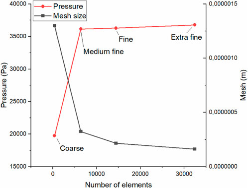
The element size is systematically adjusted for mesh convergence, focusing on pressure. Stable convergence, with changes below 5%, indicates mesh suitability. The table compares CPU time at different mesh densities, revealing increased demand with higher density. This study focuses on the 80 μm metal particles as the base show in Figure 3, leveraging prior convergence insights. Coarse meshes provide less accurate pressure predictions, but increased density yields comparable results. Results are visualized in Figure 4, correlating element counts with pressure levels during peak pressure calculations. A locally refined mesh concentrates fine elements in high-stress regions, enhancing pressure calculations. A hexahedral computational mesh is used for both fluids. The mesh size is selected according to a mesh convergence study. As mesh convergence could not be achieved perfectly in previous works (Klostermann et al., 2013), we use a uniform grid of 160 × 160 for the simulations, corresponding to the fine mesh used in Gamet, et al. (2020). The convergence was observed when the number of elements reached 15,000 or more, which corresponds to 38,000 Pa of pressure at a mesh size of 0.25 µm considered as fine mesh.
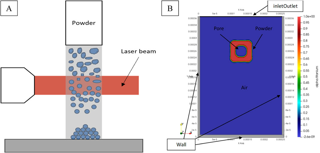
Figure 3. Schematic diagram of a (A) laser based spheroidization and (B) CFD domain representing SQ80 Pore particle using Volume of fraction.
2.4 Assumptions
Due to the complexity of associated simulations in simulating powder particle melting, the current model incorporates the following assumptions and simplifications to streamline the solution and make it more suitable for actual casting conditions:
• Since the Reynolds number is very low, the flow can be treated as laminar flow.
• The heat and mass transfer between the titanium droplet and the air was not considered in this paper since there’s no heat transfer.
• Since no velocity has been applied, the relative velocity between air and the powder particle is zero.
• The molten titanium is considered an incompressible Newtonian fluid.
• Pressure is kept at atmospheric pressure.
2.5 Analytical approach
2.5.1 Heat transfer analytical approach
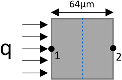
In order to validate the heat transfer simulation, Equation 1 was adopted for Explicit Finite difference Heat transfer using one-dimensional heat conduction SQ80 particle with only two nodes without considering latent heat of fusion (Buttsworth, 2001).
Equation 19 indicates the heat conduction at node one, which includes heat flux from the laser, while Equation 20 excludes heat flux since node two will only experience heat conduction transferred from node one, as shown in Figure 5.
2.5.2 Droplet equilibrium pressure analytical approach
To assess the accuracy of the simulated pressure field, we use the Young–Laplace equation to calculate the pressure jump across the interface. This analytical validation offers insights into the integrity of the simulation findings. For the sake of simplicity, inertia effects were ignored throughout validation. Validation was performed by calculating the average pressure in spherical liquid powder particles in mechanical equilibrium using the Laplace pressure mentioned below (Blank et al., 2023; Kuchma et al., 2018):
where
The Laplace pressure is computed when the droplet is at equilibrium in order to verify that the surface tension models capture the expected pressure jump across an interface.
3 Simulation result
3.1 Heat transfer result (Abaqus)
Figure 6 shows the heat transfer result from Abaqus that was applied to the SQ80 particle and shows the temperature distribution caused by the applied heat flux during the heating period. Figure 6A shows the applied heat flux magnitude while Figure 6B shows the temperature distribution on the SQ80 powder particle. The simulation does not account for particle rotation due to the laser beam’s position, and to simplify the process, instead of the particle, the laser beam was made to move. As the powder particle melts, the heat flux extends inside the workpiece and beyond, leading to increased temperatures in the surrounding regions along the Z axis.
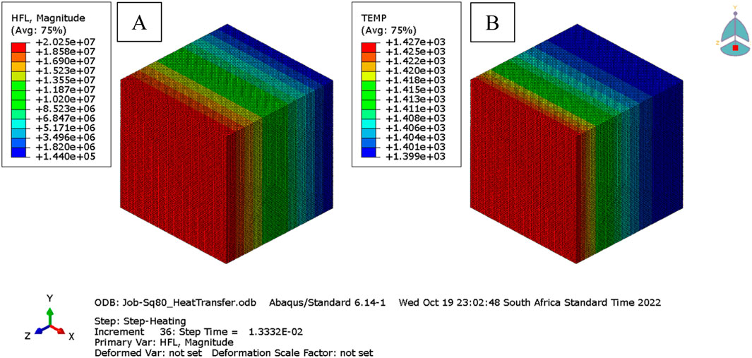
Figure 6. Abaqus SQ80 powder particle heat transfer result (A) heat flux and (B) Temperature contour plot.
A temperature plot of the powder particles is presented in Figure 7. Because the SQ80 particle is the largest in the batch and will require more heat, the temperature vs. time behavior of each chosen powder particle was plotted based on this powder particle size, making it possible to determine an acceptable heat flux and duration. 1,660°C is the melting point and 3,260 °C is the evaporation point, respectively. The computed duration and heat flux, however, are applied to the remaining powder particles, the SQ20 and SQ50. For SQ80 particles, the ideal laser heat flux was 94,170 kN/m2 at 0.06 m/s and a 1.3-mm spot diameter. SQ80 melted in 0.005 s, whereas SQ50 was melting at 2048°C and SQ20 was evaporating at 5,128°C. Sun et al. (2017) reported a similar observation. Nonetheless, at 0.0033 and 0.0015, respectively, the melting temperatures of the SQ50 and SQ20 were attained. Particles slightly smaller than SQ50 achieved spherical deformation, while those close to SQ20 contributed to dust and satellites. Fourier’s law explains thermal resistance dependence on geometry, influencing melting behavior. These findings have practical implications for controlling spheroidization processes to obtain desired particle characteristics (Cengel, 2002).
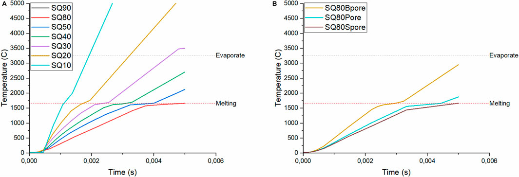
Figure 7. Distribution of temperatures during the heating of (A) pore-free powder particles and (B) SQ80 powder particles with various pore diameters.
Powder particles show a brief period of constant temperature before melting point; this is revealing of latent heat of fusion, the energy needed for phase change at constant temperature that varies with powder particle size. However, converting larger powder particles (SQ80) demands more energy due to their geometry. Particle porosity has a negligible impact on heat distribution, affecting only heat resistance. Similarly, this observation was reported by Emeis (2004). SQ20 powder particles reach the melting point quicker than the other particle sizes considered in this study (Figure 7), resulting in no temperature gradient post-melting. The liquid surface at the melting temperature indicates the overcoming of thermal resistance. In Figure 7, increasing particle size range leads to higher thermal resistance for larger particles, causing varied melting times compared to smaller particles. Two powder particles were added to the simulation: 40 µm (SQ40) and 30 μm (SQ30), as the SQ20 powder particle evaporated. The figure demonstrated that the SQ30 melted at 0.0022 s before melting very close to the evaporating mark at 3,152 °C, while the SQ40 would have melted fully away from the evaporation mark at 2,702°C, after reaching its melting point at 0.005 s. Consequently, the computed heat flux can be applied to the 40–80 μm powder range since powder particle smaller than SQ30 are evaporating and SQ90 powder particle illustrated the same behaviour as SQ80 since the size difference is minimum.
3.2 OpenFOAM result
3.2.1 Deformation of the liquid powder particle
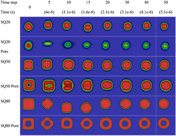
Figure 8 illustrates the simulation results of the deformation of titanium powder particles at their respective melting temperatures, highlighting the influence of particle size, geometry, and pore presence.
Surface tension plays a significant role in particle deformation, though it is not the sole factor, and its effects are more nuanced than simple proportionality to size and geometry. Surface tension acts like an elastic film at the liquid’s surface, resisting external forces that try to expand the surface area. When a particle deforms a liquid droplet, it increases the surface area, and to counteract this increase, surface tension pulls the liquid back towards its original, minimal surface area. Consequently, the surrounding liquid tends to be drawn into a spherical shape due to the surface tension effect. All liquid droplets would be approximately spherical if only the surface tension force were acting on them. If the droplet capillary number is smaller than 1, then surface tension dominates over the gravitational force (Rapp, 2017). Surface tension generates a restoring force that acts to return the droplet to its equilibrium shape and is strongest where the curvature of the droplet’s surface is greatest, i.e., at the edges and sharp corners (Moon and Migler, 2009).
Observations at specific time steps reveal distinctive deformation behaviors. At time step 10, smaller particles like SQ20 have already transitioned to spherical shapes, while larger particles and those with pores maintain irregular forms. SQ50 remains in an irregular shape, while SQ50Pore also retains its irregularity, just releasing the trapped pore. Similarly, SQ80 and SQ80Pore still resemble a square shape, with SQ80Pore showing the pore transformed into a spherical shape but still trapped inside.
At time step 15, SQ20Pore displays a prolate shape, SQ50Pore exhibits an irregular shape without a pore, while SQ80 exhibits both oblate and prolate shapes. SQ80Pore displays similar behavior to SQ80, with the addition of a spherical pore still trapped inside. By time step 50, all particles have become spherical, with the exception of SQ80Pore, which retains a trapped pore even as it assumes a spherical shape.
Moreover, it is visible that from the initial spheroid shape, the droplet is stretched toward an ellipsoid shape with its long axis in the direction of motion. This cycle continues as the droplet shape returns to a spheroid shape, then deforms into an ellipsoid with its long axis perpendicular to the motion axis, and back to a spheroid, performing repeated cycles. This dynamic deformation can be described as revolving or oscillating, where the rotation of the ellipsoid-shaped droplet around its center of mass is observed (Volkov et al., 2015).
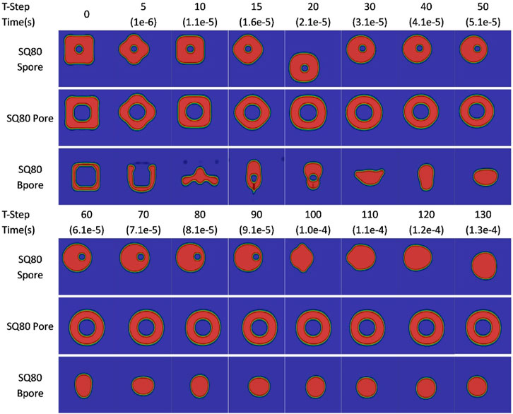
Figure 9 illustrates the SQ80Pore particle for a longer step time than that indicated in Figure 8. This accounts for the additional time required to eliminate the pore. As seen at a time step of 330, the SQ80Pore particle maintains its spherical shape with trapped air inside, however, the particle loses its spherical shape thereafter and the pore is eliminated by time step 380 as the trapped air rises towards the surrounding atmosphere and breaks open the interface layer, causing the particle to deform into an irregular shape. The pore eventually breaks open, leading to oscillations until the particle reaches equilibrium and returns to a spherical shape by time step 430. This process takes a further time steps under the same conditions. This process was also observed in Molybdenum powders by Tan et al. (2021).
If the powder solidifies before the gas escapes, irregular pore-shaped particles or spherical pore-shaped particles are formed, which can be eliminated by continuous heat inputs or increased residence time. Observations show that the particle goes through three phases namely, deformation with a pore, rising of trapped air, and deformation to a spherical shape. The times taken for these phases differ for the SQ80 particle, with the first phase taking 0.1 ms, 0.264 ms for the middle phase, and 0.185 ms for the last phase. The rising of the trapped air takes five times longer than the deformation phases, indicating the porosity’s impact on the spheroidization process. Similar behavior has been observed on other particle sizes, however, the SQ20 is quick to eliminate the pore due to its size.
Figure 10 illustrates the influence of pore size on powder particle behavior, considering the addition of SQ80Spore and SQ80Bpore particles with square pore lengths of 16 µm and 48 μm, respectively. Additionally, two separate simulations were conducted on SQ80Pore particles: one with a 50% reduction in pore size (SQ80Spore) and another with a 50% increase in pore size (SQ80Bpore). These simulations aimed to comprehensively understand the effect of pore size variations on particle dynamics.
In comparing the results, it was observed that SQ80Spore particles with reduced pore size exhibited a late movement of pores towards the droplet wall during the initial deformation phase (time step 30–90), whereas in the case of SQ80Bpore particles, the pores escaped the particle at an earlier stage, specifically during the early movement at time step 5. Simultaneously, at the same time step, SQ80Spore particles displayed an irregular shape with powder accumulating at the middle, mirroring the behavior observed in SQ80Pore particles.
Furthermore, the ascent of the pore phase was notably faster for SQ80Spore particles compared to both SQ80Pore particle variations, indicating that smaller pore sizes lead to accelerated full deformation of powder particles. Specifically, reducing the pore size by 50% resulted in a significant improvement in particle deformation time by 61%, highlighting the impact of pore size on particle behavior. Conversely, increasing the pore size led to delayed deformation, emphasizing the importance of pore size optimization in powder particle dynamics.
SQ80Spore particles retained their pores for 0.091 ms, while SQ80Pore particles maintained them for a longer duration of 0.0036 s. On the other hand, SQ80Bpore particles’ pores lasted for not more than 0.001 ms before air was trapped again, creating another pore at time step 15, which was later released at time step 30.
Due to the thin walls of SQ80Bpore, in the case of interface oscillation which elongates the droplet in either the x or y direction, it is easier for the pore to pierce the wall as air moves from high pressure to low pressure. Consequently, the air cavity inside the hollow droplet is compressed and the thickness of the liquid shell is reduced. At the same time, fluid at the contact point moves toward both sides. On the outside, the spreading liquid film develops as the liquid overcomes surface tension and viscous forces, while liquid inside the liquid shell converges to the impact center, resulting in an increase in the thickness of the central liquid film.
Specifically, the pore is repelled by the adjacent droplet surface, then travels a considerable distance within the droplet, ultimately pushing against the opposite side of the droplet surface. This dynamic process can result in the pinch-off of the droplet when the local Weber number surpasses a critical threshold. Similar behavior was seen by Li et al. (2024). They also noted that the non-dimensional bubble oscillation period deviates significantly between two experiments, mainly attributed to the difference in the density ratio (α) and the pore penetration condition being insensitive to the curvature of the fluid-fluid interface.
In the context of droplet pinch-off, it is imperative for inertia to overcome surface tension in the presence of viscous dissipation. When the inertia of the traveling vortex ring bubble overcomes the surface tension of the droplet, even in the presence of viscous dissipation, the droplet undergoes a division into two daughter droplets. Kant and Banerjee (2023) indicated that it is impossible to pierce through a droplet without a density difference. This is observed in a trivial simulation and is expected, since without any density difference there will be no Rayleigh-Taylor Piercing (RTP). This suggests that both surface tension and inertia play significant roles in this process. Unfortunately, this phenomenon falls beyond the scope of our study.
Additionally, in terms of oscillation, powder particles with larger pores oscillated for a longer time compared to particles with smaller pores. This excessive oscillation increases the likelihood of breaking off particles with thin walls, which can lead to the formation of satellites. This behavior was observed during the deformation of SQ80Bpore from time step 5 to 15, during which small droplets were formed and floated to the domain wall.
3.2.2 Diameter effect on the deformation of the liquid powder particle
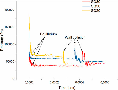
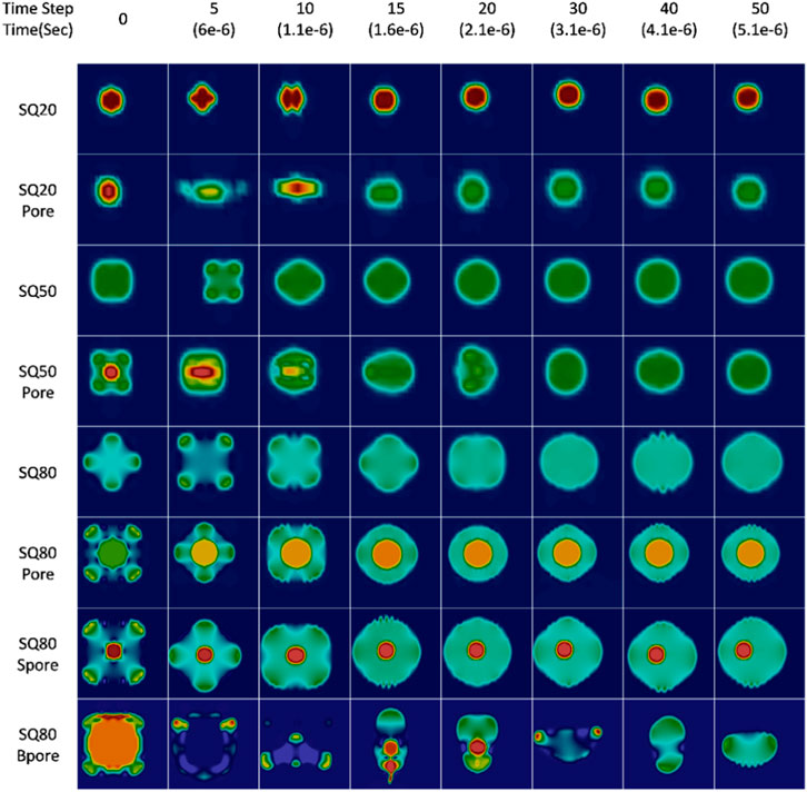
Figure 11 and Figure 12 illustrate pressure versus time graphs for solid droplets and porosity in the system, respectively. The illustrated pressure corresponds to the maximum pressure of each droplet in the simulation. Figure 13 illustrates the droplet orientations and the pressure’s impact on them. The greatest pressure was found to be merely within the droplets, particularly at the pores and sharp corners.
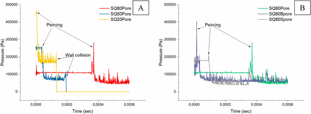
Figure 12. Pressure comparison of (A) the SQ80, SQ50, and SQ20 with porosity and (B) SQ80 with different porosity.
At time step 0 in Figure 13, since all of the droplets are still square-shaped, the surface tension effect is visible at the droplets’ sharp edges in terms of Laplace pressure. Sharp edges or corners on a liquid surface indicate areas of high curvature, which usually results in higher surface energy (Chen, et al., 2017). To balance their pressure, the droplets reduce their surface area and smooth off sharp edges until they attain equilibrium by oscillating into different shapes, identical to oblate and prolate forms. When equilibrium is attained, the droplet’s pressure remains constant as time passes. However, porosity indicated significant pressure due to the density ratio and the magnitude of the curvature (Li et al., 2024; Kant and Banerjee, 2023).
The time it takes for the pore to pierce through the droplet during deformation is proportional to its pressure. For instance, at time step 0, the SQ80Bpore droplet is observed to pierce through the wall. As the pore pierces through, surface tension exerts tremendous pressure at that point in order to keep the droplet’s surface area. This droplet breaks up earlier because its walls are thin, resulting in the formation of a neck. However, for the same droplet at time steps 5–10, severe deformation is observed, and pressure at specific regions of the droplet is extremely lowered after breaking apart, which may lead to another droplet breaking because necking development occurs. Chen et al. (2017) state that droplet breakage will not occur if We < 1. However, the Reynolds number also influences droplet behavior. High Reynolds numbers suggest high inertial forces, while low Reynolds numbers indicate high viscous forces, as laminar flow reduces droplet breakdown (Kékesi et al., 2014; Yang et al., 2016; Chen et al., 2017).
Figure 11 shows peak pressure. This occurs when the pore pierces the droplet or when the droplet collides with the wall, becoming severely distorted. The pressure surged fast as surface tension drove the droplet back to equilibrium. This means that every force that alters the spherical shape of the droplet causes an increase in pressure, which is determined by the surface tension force. During equilibrium, as observed, there are fewer pressure peaks. SQ20 has the highest pressure due to its modest curvature when compared to the other droplets. Pressure reduces as droplet size (curvature) increases, for example, SQ80 has lower pressure than SQ20. At the beginning of the simulation, the SQ20 droplet oscillates and changes shape. This initial stage, characterized by increased pressure, arises because the droplet has a sharp radius. The pressure steadily lowers until it reaches equilibrium, where it remains constant as the droplet retains it spherical shape. This behavior was found in all droplets, even those containing pores.
Figure 12A illustrates the pressure behavior of droplets with porosity. Surface tension acts at the interface between the outer droplet surface and the pore surface. It tends to reduce the surface area of both interfaces, which influences the overall shape and stability of the droplet. The pressure behavior is similar to that of droplets without pores; as illustrated in Figure 11, the main difference is that the pore raises the droplet’s pressure magnitude due to its smaller curvature. The pore smoothes out faster than the host droplet due to its larger curvature size. A droplet with a pore acts similarly to a droplet bubble, with two interfaces: one between the air and the molten droplet, and one between the trapped air and the molten droplet. According to Laplace’s law, the pressure difference between the inside and outside of a bubble is inversely proportionate to its radius. This indicates that pores have a higher internal pressure for the same surface tension.
Figure 12B illustrates the effect of different porosity sizes on a droplet of the same diameter. Larger pores penetrate droplets faster than smaller ones due to the shorter distance between the inner and outer interfaces. However, the small pore size of SQ80Spore implies that it does not stay in the droplet for long, whereas the medium-sized pore persists in the droplet after the particles’ outer interface has change to spherical. Pressure peaks are connected with surface modifications, such as a pore piercing or a droplet with sharp edges, because they increase interface stability.
The influence of pressure on the droplet is determined by the change in the curvature of the droplet rather than by time, since curvature is inversely proportional to pressure. The pressure affects the deformation rate, the mean tension force for a small droplet with a small surface is high, resulting in a high deformation rate. This explanation provides a comprehensive understanding of the pressure effects on the deformation of liquid droplets in the system.
3.3 Simulation validation
Ensuring the precision and dependability of the generated results requires validating both the OpenFOAM simulation and the heat transfer. We present a thorough validation analysis in this section to evaluate the fidelity of our models.
3.3.1 Heat transfer in the solid state
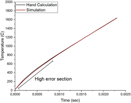
In the conducted comparative study between the simulation model and analytical solution, the main focus was on heat transfer and the effect of surface tension on molten powder particles. The simulation utilized the widely adopted Gaussian and solid heat conduction model, and corresponding surface heat fluxes. The simulation results indicated that a higher laser power than the machine minimum of 1800 W would be required for the Spheroidization process. To verify the accuracy of the simulation model, a hand calculation was performed for a specific powder particle (SQ80) at the determined surface heat flux. Both simulation and analytical solution used the same physical properties and made simplifications by neglecting convection, radiation, and temperature-dependent properties. The comparison between simulation and analytical results showed a maximum error percentage of 7% for a few seconds of the calculation as shown in Figure 14. The fact that the maximum value was applied throughout the hand calculation, but the heat flux value was applied progressively in the Abaqus simulation until it reached the maximum value contributed to the error percentage. This confirmed that the simulation model was a good representation of the real system and suitable for predicting the spheroidization process. However, the hand calculation excluded the latent heat of fusion and employed some boundary condition simplifications to reduce complexity.
3.3.2 Deformation in liquid state
Since the liquid phase was performed on another simulation software, a second validation had to be performed to cover for when the powder particles were in the liquid form. In this section of the results, only the pressure difference between the droplet and the surrounding air was considered. The viscous stress was neglected since there was no applied velocity, only the gravity was added. Both result from the powder particle without porosity and without porosity was considered in the validation to improve accuracy. The validation results obtained through the comparison of analytical calculation and simulation results is shown in Table 2. The pressure difference between the SQ80 and the SQ20 powder particles shows not more than 15 percent difference, while the SQ50 powder particle shows a 15 percent difference. Powder particles with porosity show slight high error of 16% error this can be contributed by the solver when capturing the curvature during simulation (Klostermann, et al., 2013). The difference in the error percentage is due to the difference in deformation of the particles since they do not deform in the same manner as a result of the spurious current that can affect the accuracy of the results (Guo, et al., 2015). The analytical calculation also showed that the smallest powder particle would have a higher-pressure difference compared to the larger particles, similar to the simulation. Another factor contributed to the error difference is the difficult in results under the interFoam solver indicated by (Klostermann, et al., 2013).

Table 2. Pressure validation result comparing the droplet’s computed Laplace pressure with and without a pore to the simulation.
4 Conclusion
This study makes substantial contributions to our understanding of heat transfer kinetics, deformation mechanisms, and the effect of surface tension on powder particle spheroidization. Through thorough modeling, our model effectively predicted and reproduced the spheroidization process, closely mimicking real-world circumstances. Our findings show that melting temperatures of 1,660°C within 0.005 s require a heat flux of 94 MW/m2 (equivalent to laser power of 1.8 kW) for 80 μm powder particles. Particles smaller than 30 μm cannot be handled without evaporation. The laser intensity and residence period without evaporation may effectively treat powder particles ranging from 80 to 30 μm. We discovered that smaller particles deform faster, resulting in smaller spherical particles during spheroidization. Furthermore, we discovered that porosity prolongs particle deformation, influencing the spheroidization process. Interestingly, particles larger than 60 µm can maintain a spherical form even with pores. The PS process was able to process Ti64 at a range of 20–80 µm (Slotwinski et al., 2014; Wahll et al., 1961; Samokhin et al., 2019), this indicates that laser-based system might be suitable for this process.
Our research demonstrates that laser spheroidization offers a feasible and promising alternative to traditional methods like gas atomization and plasma spheroidization. Unlike these conventional techniques, which require extensive equipment and experimental validation, the laser method offers the advantage of minimal equipment while still allowing for precise control over the spheroidization process. Gas atomization faces issues like broad particle size distribution and oxidation risk, while plasma spheroidization is costly and energy-intensive. Laser spheroidization, on the other hand, enables better control over particle shape, with fewer equipment requirements, making it a cost-effective and scalable option.
The findings included an investigation of heat flux distribution, temperature gradients, irregular particle deformation, and the effect of surface tension on droplet formation. This insight substantially aids in the optimization of laser power and understanding of powder behavior, particularly in terms of Ti-6Al-4V characteristics. Our simulations using Abaqus for solid square powder particles of different sizes (80 μm, 50 μm, and 20 μm), as well as employing the same irregular-shaped particles as droplets in OpenFOAM, offered useful insights into the spheroidization process. Despite its relatively recent development and the limited range of applications explored, laser spheroidization is poised for rapid growth as its benefits become more apparent. As the technology matures, research and development efforts are expected to increase, further advancing the field.
Future research must improve the accuracy and application of current modeling efforts, as well as address a number of crucial issues. First, a comprehensive CFD phase change simulation model that appropriately considers powder particle deformation during phase transition and solidification is required. Furthermore, developing a model that incorporates the effects of inert gas pressure on particle deformation is critical for accurate control in actual applications. Advanced modeling of the behavior of evaporated powder particles, including condensation and solidification, is also required. Investigating the effect of velocity on powder particle deformation will aid in the establishment of a link between particle velocity and deformation, thereby enhancing prediction accuracy. Experimental validation using a laser power of 2 kW is required to calibrate and modify the simulation models using empirical data. Furthermore, combining the Discrete Element Method (DEM) with Computational Fluid Dynamics (CFD) will result in a more detailed and accurate description of particle interactions and dynamics, allowing for a better understanding of the complex phenomena at hand. Addressing these issues will considerably improve the modeling framework, resulting in more accurate predictions and better-informed process optimization. Exploration of different irregular shape.
Data availability statement
The original contributions presented in the study are included in the article/supplementary material, further inquiries can be directed to the corresponding author.
Author contributions
PB: Writing–original draft, Writing–review and editing. DD: Funding acquisition, Supervision, Writing–review and editing. NA: Funding acquisition, Supervision, Writing–review and editing. SP: Funding acquisition, Supervision, Writing–review and editing.
Funding
The author(s) declare that financial support was received for the research, authorship, and/or publication of this article. The publication of this work was supported by funding from the Department of Mechanical and Mechatronics Engineering at Tshwane University of Technology and the Council for Scientific and Industrial Research (CSIR).
Acknowledgments
The author gratefully acknowledges financial support from the Tshwane University of Technology and the Council for Scientific and Industrial Research (CSIR) (Grant No. CPAM-HLM4NAX), which enabled this study and funded the publication. Additionally, the use of generative AI technologies, specifically ChatGPT version 4 by OpenAI, is acknowledged in the preparation of this article.
Conflict of interest
The authors declare that the research was conducted in the absence of any commercial or financial relationships that could be construed as a potential conflict of interest.
Publisher’s note
All claims expressed in this article are solely those of the authors and do not necessarily represent those of their affiliated organizations, or those of the publisher, the editors and the reviewers. Any product that may be evaluated in this article, or claim that may be made by its manufacturer, is not guaranteed or endorsed by the publisher.
References
Ahmad, J., Mohammad, V., Pooyan, B., and Nasser, K. (2023). An eXtended finite element method implementation in COMSOL multiphysics: thermo-hydro-mechanical modeling of fluid flow in discontinuous porous media. Comput. Geotechnics 159, 105458. doi:10.1016/j.compgeo.2023.105458
Anderson, J. D. (2010). “Brief history of the early development of theoretical and experimental fluid dynamics,” in Encyclopedia of aerospace engineering. Editors B. Richard, and S. Wei (Washington USA: John Wiley and Sons).
Arai, E., Tartakovsky, A., Holt, R. G., Grace, S., and Ryan, E. (2020). Comparison of surface tension generation methods in smoothed particle hydrodynamics for dynamic systems. Comput. and Fluids 203, 104540. doi:10.1016/j.compfluid.2020.104540
Bao, Q., Yang, Y., Wen, X., Guo, L., and Guo, Z. (2021). The preparation of spherical metal powders using the high-temperature remelting spheroidization technology. Mater. and Des. 199, 109382. doi:10.1016/j.matdes.2020.109382
Blank, M., Nair, P., and Pöschel, T. (2023). Modeling surface tension in Smoothed Particle Hydrodynamics using Young–Laplace pressure boundary condition. Comput. Methods Appl. Mech. Eng. 406, 115907. doi:10.1016/j.cma.2023.115907
Boxin, D., De Ruiter, J., and Schroen, K. (2019). Application of microfluidics in the production and analysis of food foams. Foods 21. doi:10.3390/foods8100476
Buttsworth, D. R. (2001). A finite difference routine for the solution of transient one dimensional heat conduction problems with curvature and varying thermal properties. Toowoomba Qld: Faculty of Engineering and Surveying Technical Reports.
Bybordiani, M., Latif Aghili, A., Soares Jr, D., Godinho, L., and Dias-da-Costa, D. (2021). An XFEM multi-layered Heaviside enrichment for fracture propagation with reduced enhanced degrees of freedom. Int. J. Numer. Methods Eng. 122, 3425–3447. doi:10.1002/nme.6669
Cano-Lozano, J. C., Bolaños-Jiménez, R., Gutiérrez-Montes, C., and Martínez-Bazán, C. (2015). The use of Volume of Fluid technique to analyze multiphase flows: specific case of bubble rising in still liquids. Appl. Math. Model. 39 (12), 3290–3305. doi:10.1016/j.apm.2014.11.034
Celik, A., Bonten, C., Togni, R., Kloss, C., and Goniva, C. (2021). A novel modeling approach for plastics melting within a CFD-DEM framework. Polymers 13, 227. doi:10.3390/polym13020227
Chen, Y., DeMauro, E., Wagner, J., Arienti, M., Guildenbecher, D., Farias, P., et al. (2017). “Aerodynamic breakup and secondary drop formation for a liquid metal column in a shock-induced cross-flow,” in 55th AIAA Aerospace Sciences Meeting, Grapevine, Texas, 9-13 January 2017. doi:10.2514/6.2017-1892
Colagrossi, A., and Landrini, M. (2003). Numerical simulation of interfacial flows by smoothed particle hydrodynamics. J. Comput. Phys. 191 (2), 448–475. doi:10.1016/s0021-9991(03)00324-3
Cosimo, A., Fachinotti, V., and Cardona, A. (2013). An enrichment scheme for solidification problems. Comput. Mech. 52, 17–35. doi:10.1007/s00466-012-0792-9
Dongqing, L. (2013). “Basic methodology,” in Encyclopedia of microfluidics and nanofluidics (New York: Springer US), 6–12.
Elgeti, S., and Saucerland, H. (2016). Deforming fluid domains within the finite element method. Archives Comput. Methods Eng. 23, 323–361. doi:10.1007/s11831-015-9143-2
Emeis, S. (2004). The discovery of latent heat 250 years ago. Meteorol. Z. 13 (4), 329–333. doi:10.1127/0941-2948/2004/0013-0329
Gamet, L., Scala, M., Roenby, J., Scheufler, H., and Pierson, J.-L. (2020). Validation of volume-of-fluid OpenFOAM® isoAdvector solvers using single bubble benchmarks. Comput. and Fluids 213, 104722. doi:10.1016/j.compfluid.2020.104722
Gereltbyamba, B., and Lee, C. (2018). Behavior of settling inertial particles in a differentially heated cubic cavity at moderate Rayleigh number. J. Mech. Sci. Technol. 32 (7), 3169–3182. doi:10.1007/s12206-018-0620-z
Guildenbecher, D. R., Lopez-Rivera, C., and Sojka, P. E. (2009). Secondary atomization. Exp. Fluids 46, 371–402. doi:10.1007/s00348-008-0593-2
Guo, S., Hao, Z., Ma, R., Wang, P., Shi, L., Shu, Y., et al. (2023). Preparation of spherical WC-Co powder by spray granulation combined with radio frequency induction plasma spheroidization. Ceram. Int. 49 (8), 12372–12380. doi:10.1016/j.ceramint.2022.12.097
Guo, Z., Fletcher, D. F., and Haynes, B. S. (2015). Implementation of a height function method to alleviate spurious currents in CFD modelling of annular flow in microchannels. Appl. Math. Model. 39 (16), 4665–4686. doi:10.1016/j.apm.2015.04.022
Harlow, F. H., and Welch, J. E. (1967). Numerical calculation of time-dependent viscous incompressible flow of fluid with free surface. Phys. Fluids 10 (12), 2182–2189. doi:10.1063/1.1761178
He, M., Bishop, P. J., Kassab, A. J., and Minardi, A. (1995). A coupled fdm/bem solution for the conjugate heat transfer problem. Numer. Heat. Transf. Part B Fundam. 28 (2), 139–154. doi:10.1080/10407799508928826
Hsiao, G. C., Schnack, E., and Wendland, W. L. (1999). A hybrid coupled finite-boundary element method in elasticity. Comput. Methods Appl. Mech. 173, 287–316. doi:10.1016/s0045-7825(98)00288-6
Huang, K., Elton, E. S., Henderson, H. B., Harward, N. K., Clarke, E. M., Winston, L. D., et al. (2023). The hydride-dehydride process combined with plasma spheroidization: an alternative route for producing spherical metallic powders of U-6 wt.% Nb. Adv. Powder Technol. 34 (4), 103992. doi:10.1016/j.apt.2023.103992
Jeong, W., and Seong, J. (2014). Comparison of effects on technical variances ofComputational fluid dynamics (CFD) software based on finite element and finite volume methods. Int. J. Mech. Sci. 78, 19–26. doi:10.1016/j.ijmecsci.2013.10.017
Ji, D., Lei, W., and Liu, Z. (2020). Finite element method and boundary element method iterative coupling algorithm for 2-D elastodynamic analysis. Comp. Appl. Math. 39 (3), 218. doi:10.1007/s40314-020-01233-4
Kant, K., and Banerjee, R. (2023). Effect of density ratios on droplet breakup for Newtonian and power-law fluids. Int. J. Multiph. Flow 167, 104561. doi:10.1016/j.ijmultiphaseflow.2023.104561
Kékesi, T., Amberg, G., and Prahl Wittberg, L. (2014). Drop deformation and breakup. Int. J. Multiph. Flow 66, 1–10. doi:10.1016/j.ijmultiphaseflow.2014.06.006
Khoei, A. R. (2014). “Extended FEM (X-FEM) formulation,” in Extended finite element method: theory and applications (Wiley Online Books), 31–76.
Klostermann, J., Schaake, K., and Schwarze, R. (2013). Numerical simulation of a single rising bubble by VOF with surface compression. Int. J. Numer. Methods Fluids 71 (8), 960–982. doi:10.1002/fld.3692
Kuchma, A. E., Shchekin, A. K., Martyukova, D. S., and Savin, A. V. (2018). Dynamics of ensemble of gas bubbles with account of the Laplace pressure on the nucleation stage at degassing in a gas-liqiud mixture. Fluid Phase Equilibria 455, 63–69. doi:10.1016/j.fluid.2017.09.022
Li, S., Zhao, Z., Zhang, A. M., and Han, R. (2024). Cavitation bubble dynamics inside a droplet suspended in a different host fluid. arXiv:2401.00769.
Li, Y. L., and Ishigaki, T. (2004). Spheroidization of titanium carbide powders by induction thermal plasma processing. J. Am. Ceram. Soc. 84 (9), 1929–1936. doi:10.1111/j.1151-2916.2001.tb00939.x
Lu, X., Lin, X., Chiumenti, M., Cervera, M., Hu, Y., Ji, X., et al. (2019). Residual stress and distortion of rectangular and S-shaped Ti-6Al-4V parts by Directed Energy Deposition: modelling and experimental calibration. Addit. Manuf. 26, 166–179. doi:10.1016/j.addma.2019.02.001
Mills, K. C.National Physical Laboratory (Great Britain)ASM International (2002). Recommended values of thermophysical properties for selected commercial alloys. Ohio: Woodhead and ASM International.
Mishra, A. K., and Kumar, A. (2019). Numerical and experimental analysis of the effect of volumetric energy absorption in powder layer on thermal-fluidic transport in selective laser melting of Ti6Al4V. Opt. and Laser Technol. 111, 227–239. doi:10.1016/j.optlastec.2018.09.054
Moon, D., and Migler, K. B. (2009). Measurement of dynamic capillary pressure and viscosity via the multi-sample micro-slit rheometer. Chem. Eng. Sci. 64 (22), 4537–4542. doi:10.1016/j.ces.2009.02.039
Nkhasi, N., du Preez, W., and Bissett, H. (2021). Plasma spheroidisation of irregular Ti6Al4V powder for powder bed fusion. Metals 11 (11), 1763. doi:10.3390/met11111763
Nkhasi, N., du Preez, W., and Bissett, H. (2023). Plasma spheroidisation and characterisation of commercial titanium grade 5 powder for use in metal additive manufacturing. MATEC Web Conf. 388, 03004. doi:10.1051/matecconf/202338803004
Ökten, K., and Biyikoğlu, A. (2021). Development of thermal model for the determination of SLM process parameters. Opt. and Laser Technol. 137, 106825. doi:10.1016/j.optlastec.2020.106825
Ping, L., Zhihui, W., Chao, Y., and Zai-Sha, M. (2010). Experimental investigation and numerical simulation of mass transfer during drop formation. Chem. Eng. Sci. 65 (20), 5517–5526. doi:10.1016/j.ces.2010.07.022
Popov, V. V., Grilli, M. L., Koptyug, A., Jaworska, L., Katz-Demyanetz, A., Klobcar, D., et al. (2021). Powder bed fusion additive manufacturing using critical raw materials: a review. Mater. (Basel) 14 (4), 909. doi:10.3390/ma14040909
Qin, F., Qi, H., Yanpeng, G., Tong, A., Pei, C., and Yanwei, D. (2022). The application of FEM-BEM coupling method for steady 2D heat transfer problems with multi-scale structure. Eng. Analysis Bound. Elem. 137, 78–90. doi:10.1016/j.enganabound.2022.01.009
Rapp, B. E. (2017). “Chapter 21 - capillarity,” in Microfluidics: modelling, mechanics and mathematics. Editor B. E. Rapp (Elsevier Science), 445–451. doi:10.1016/B978-1-4557-3141-1.50021-6
Rasthofer, U., Henke, F., Wall, W. A., and Gravemeier, V. (2011). An extended residual-based variational multiscale method for two-phase flow including surface tension. Comput. Methods Appl. Mech. Eng. 200 (22), 1866–1876. doi:10.1016/j.cma.2011.02.004
Reddy, M. V., Banka, H., Ramana, S. V., Babu, P. R., Thejasree, P., and Joseph, J. (2023). State of art on FEM approach in inverse heat transfer problems for different materials. Mater. Today Proc. doi:10.1016/j.matpr.2023.06.323
Romano, J., Ladani, L., Razmi, J., and Sadowski, M. (2015). Temperature distribution and melt geometry in laser and electron-beam melting processes – a comparison among common materials. Addit. Manuf. 8, 1–11. doi:10.1016/j.addma.2015.07.003
Samokhin, A. V., Alekseev, N. V., Astashov, A. G., Kirpichev, D. E., Fadeev, A. A., Sinaiskiy, M. A., et al. (2019). Synthesis and processing of powder materials in DC arc thermal plasma. J. Phys. Conf. Ser. 1393 (1), 012126. doi:10.1088/1742-6596/1393/1/012126
Scheufler, H., and Roenby, J. (2021). TwoPhaseFlow: a framework for developing two phase flow solvers in OpenFOAM. OpenFOAM® J. 3, 200–224. doi:10.51560/ofj.v3.80
Slotwinski, J. A., Garboczi, E. J., Stutzman, P. E., Ferraris, C. F., Watson, S. S., and Peltz, M. A. (2014). Characterization of metal powders used for additive manufacturing. J. Res. Natl. Inst. Stand Technol. 119, 460–493. doi:10.6028/jres.119.018
Spalart, P., and Venkatakrishnan, V. (2016). On the role and challenges of CFD in the aerospace industry. Aeronautical J. 120 (1223), 209–232. doi:10.1017/aer.2015.10
Sun, P., Fang, Z. Z., Zhang, T., and Xia, Y. (2017). Review of the methods for production of spherical Ti and Ti alloy powder. JOM J. Minerals, Metals and Mater. Soc. 69 (10), 1853–1860. doi:10.1007/s11837-017-2513-5
Tan, Z., Zhou, Z., Wu, Z., Wang, Y., Shao, W., Guo, X., et al. (2021). In situ synthesis of spherical WMo alloy powder for additive manufacturing by spray granulation combined with thermal plasma spheroidization. Int. J. Refract. Metals Hard Mater. 95, 105460. doi:10.1016/j.ijrmhm.2020.105460
Volkov, R. S., Kuznetsov, G. V., and Strizhak, P. A. (2015). Water droplet deformation in gas stream: impact of temperature difference between liquid and gas. Int. J. Heat Mass Transf. 85, 1–11. doi:10.1016/j.ijheatmasstransfer.2015.01.078
Wahll, M. J., Van Orsdel, J. R., and Fischer, R. B. (1961). Spheroidization of irregularly shaped metal powders. Powder Metall. 4 (8), 48–64. doi:10.1179/pom.1961.4.8.005
Xielin, Z., Ning, A., Guangyu, Y., Jian, W., Huiping, T., Meie, L., et al. (2021). Enhancing standard finite element codes with POD for reduced order thermal analysis: application to electron beam melting of pure tungsten. Mater. Today Commun. 29, 102796. doi:10.1016/j.mtcomm.2021.102796
Yang, W., Jia, M., Sun, K., and Wang, T. (2016). Influence of density ratio on the secondary atomization of liquid droplets under highly unstable conditions. Fuel 174, 25–35. doi:10.1016/j.fuel.2016.01.078
Yanko, T., Brener, V., and Ovchinnikov, O. (2020). “Production of spherical titanium alloy powders used in additive manufacturing from titanium scrap,” in MATEC Web of Conferences. 321, Nantes, France, June 10-14, 2020, 07008. doi:10.1051/matecconf/202032107008
Yu, K., Kadarman, A. H., and Djojodihardjo, H. (2010). Development and implementation of some BEM variants—a critical review. Eng. Analysis Bound. Elem. 34, 884–899. doi:10.1016/j.enganabound.2010.05.001
Keywords: titanium alloy powder, spheroidization, laser beam, spherical, computation
Citation: Baloyi P, Desai DA, Arthur NKK and Pityana SL (2024) Modeling the interaction between powder particles and laser heat sources. Front. Manuf. Technol. 4:1411971. doi: 10.3389/fmtec.2024.1411971
Received: 03 April 2024; Accepted: 30 September 2024;
Published: 25 October 2024.
Edited by:
Nikolaos Karkalos, National Technical University of Athens, GreeceReviewed by:
Ramu Murugan, Amrita Vishwa Vidyapeetham University, IndiaNan Gui, Tsinghua University, China
Copyright © 2024 Baloyi, Desai, Arthur and Pityana. This is an open-access article distributed under the terms of the Creative Commons Attribution License (CC BY). The use, distribution or reproduction in other forums is permitted, provided the original author(s) and the copyright owner(s) are credited and that the original publication in this journal is cited, in accordance with accepted academic practice. No use, distribution or reproduction is permitted which does not comply with these terms.
*Correspondence: P. Baloyi, cGJhbG95aTFAY3Npci5jby56YQ==
 P. Baloyi
 D. A. Desai
 N. K. K. Arthur1