
95% of researchers rate our articles as excellent or good
Learn more about the work of our research integrity team to safeguard the quality of each article we publish.
Find out more
ORIGINAL RESEARCH article
Front. Manuf. Technol. , 23 June 2022
Sec. Additive Processes
Volume 2 - 2022 | https://doi.org/10.3389/fmtec.2022.919738
 Marie Wegner1,2*
 Tobias S. Hartwich1Emil Heyden1Lukas Schwan1Johann Schwenke1Nadine Wortmann1Dieter Krause1
In this publication, the potentials of additive manufacturing in the field of sustainability and individualization for aviation and medical technology are presented. Design approaches for each application field as well as examples in the fields are shown. In the field of aviation, structures can be manufactured so that they are load path optimized. This has a great lightweight potential and results in a low resource consumption. The examples contain the design of an aircraft cabin partition using the Direct Energy Deposition process and the optimization of load introduction points directly integrated into the sandwich core. Furthermore, in medical technology, additive manufacturing can be used to produce patient-specific models based on original medical imaging data, which can be used for training of medical treatments, quality assurance or for the validation of new developed medical devices. As examples a stroke simulation model containing a modular aortic model as well as functional stenose models are shown. Furthermore, the use of AM molds to generate a deformable bladder shell and a prostate phantom are described.
The current megatrends of sustainability and individualization are drivers for the use of additive manufacturing. One goal in the product development is to save resources in operation and production. Local production with the support of additive manufacturing helps to save transport costs and to keep the CO2 footprint low (Ford and Despeisse, 2016). Additive manufacturing can be used to produce individualized products, offering suppliers the opportunity to fulfill customer-specific wishes (Wünsche, 2015) and to produce geometrically complicated products (Gibson et al., 2015). A growing application field of AM are thus the medial technology and the aviation industry. In these fields the material properties of AM enable the use for various purposes, ranging from simple demonstrative models to functional models that reproduce mechanical, biological or physiological properties.
In the aviation sector, energy consumption and the associated emissions like CO2 depend directly on the mass moved. In the aerospace industry in particular, increased production costs can be offset by savings throughout the entire life cycle (Krause et al., 2018). Additive manufacturing offers the chance to achieve the best possible material utilization at minimum weight by exploiting design freedom. Traditionally, sandwich structures are used in lightweight design applications, for example in aircraft cabins, due to their high weight-specific properties. The latest trend is to use modular hybrid design in which the individual panels have different designs depending on the type and height of the load (Hanna et al., 2021). Especially in highly loaded areas, AM offers potential by minimizing interfaces and integrating local reinforcements for load introduction directly into the structure.
In the presented approaches, topology optimization is used to determine load path optimized structures that can be implemented using additive manufacturing to improve the critical load introduction into the lightweight design. The first example is an aircraft partition to which a cabin attendant seat is attached, whereby enormous loads must be withstood in case of a crash. To print the partition in one piece, a Direct Energy Deposition (DED) process is coupled with a robotic arm to achieve a particularly large build envelope (Dambietz et al., 2021). The second example is the load path optimized design of load introductions into the additive manufactured core of sandwich structures (Schwenke et al., 2020; Schwenke and Krause, 2020). Here, the global core structure determines the global sandwich properties and the local loads are applied by optimized local reinforcements directly integrated into the structure.
A major potential of additive manufacturing in the field of medical research and clinical application is the individualization and mass personalization of products (Spallek and Krause, 2016). In medical training, planning, and quality assurance AM offers the possibility to custom-built models based on specific interests or individual patient needs, while commercial models won’t suffice (Silvestro et al., 2020; Wegner et al., 2021a). This is enhanced by using three-dimensional patient data sets from medical imaging as a basis for design development and leads to a special procedure for the creation of medical training devices like simulation models and medical phantoms.
One of the following presented examples in medical technology is the development of individualized blood vessel models for a modular medical simulator used in medical training of neurovascular interventions. These additive manufactured models are used to replicate individual patient anatomy of intracranial and cervical vascular diseases like aneurysms (Spallek and Krause, 2017), ischemic strokes (Wortmann et al., 2022) or stenosis (vascular constrictions) (Wortmann et al., 2021b), to achieve a realistic training scenario for medical staff. A distinction is made between models that essentially represent the geometric properties, like aneurysm models, aortic model (Wortmann et al., 2021a) and functional models, as represented by the stenoses, which change their state (show an opening behavior) as a result of treatment. All models are used in a realistic working environment using realistic treatment tools. The development of a geometric and a functional model will be explained with one example each.
To ensure that the image resolution or the accuracy of a medical procedure remains within defined tolerances so called phantoms are used in medical imaging (Silvestro et al., 2020; Wegner et al., 2021a). Phantoms are physical models that mimic biological tissue and its properties in medical imaging, such as X-ray absorption properties in computer tomography (CT) or magnetic resonance relaxation times in magnetic resonance imaging (MRI). Additive manufacturing processes offer the possibility of producing phantoms in small quantities with a high degree of geometric freedom designed for a defined application (Mitsouras et al., 2015; Wegner et al., 2021a). There are two main manufacturing options for producing phantoms using AM. On the one hand, the desired model or part of the model can be manufactured directly with AM, and on the other hand, indirect manufacturing can be used to manufacture a mold (Wegner et al., 2021a; 2021b). Examples of an additive manufactured mold for a bladder phantom and a multi-layer prostate mold will be shown.
Two approaches for the development of additive manufacturing in the fields of aviation and medical technology are described in the following section. In the field of aviation, in Section 2.1 a new approach for the development of additively manufactured aircraft cabin monuments is presented. Furthermore, the potentials of AM in aviation are shown for the optimization of the local load introduction points in sandwich structures and a corresponding approach is presented in Section 2.2. The approach for developing AM models in the medical field is described in 2.3. One of the following presented examples in medical technology uses a medical training and research simulator as a basis for the development of a stroke simulation model used in medical training of neurovascular interventions. The medical neurovascular simulator is presented in Section 2.4.
AM printing technologies and materials used are mentioned in the results section, where the specific examples in both application fields are described in detail. AM technologies range from Fused Deposition Modeling (FDM), Stereolithography (SLA) to Direct Energy Deposition (DED).
The challenge in the design of aircraft cabin monuments is to develop components that are as light and at the same time as reliable as possible. Furthermore, due to the high costs, the experiments to be conducted are to be minimized. In the design of conventional cabin components made of sandwich materials, the building block approach has become established (Department of Defense, 2002). This divides the product into different levels of complexity. On the lowest level are the material tests, with a large number of tests being carried out here. Then, these are transferred to the next higher level. The higher the level, the lower the amount of testing. Finally, at the highest level, there is only one full-size test for verification. In order to obtain the relevant interface forces at the intermediate levels, a top-down approach starting from the product level must be carried out in addition to the bottom-up approach described. This interaction is described by the Wishbone model (Ostergaard et al., 2011). In the following, this Wishbone model is adapted for the design of additively manufactured aircraft cabin monuments.
Developed structural concepts should cover in their entirety all geometric and mechanical aspects of an aircraft cabin part. Furthermore, particularly stressed areas in a global structure should additionally be examined locally by simulation and experiment. In the following, an approach is developed which, on the one hand, transfers the available results from the coupon level to higher levels and, on the other hand, identifies locally interesting areas starting from the entire product. This approach is based on the Wishbone model of (Ostergaard et al., 2011), which is a combination of the Building Block Approach (BBA) (Department of Defense, 2002) and a multiscale analysis (Fontecha Dulcey, 2018). With the help of this approach, individual substructures are additionally identified, on which local effects are to be investigated. The developed approach is visualized in Figure 1.
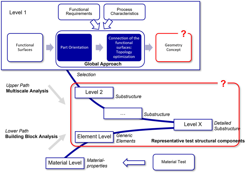
FIGURE 1. Approach to the design of additively manufactured aircraft cabins monuments.
Via the lower path, a step-by-step validation of the developed FE models is performed. At the beginning, different material models are set up based on the material tests. Depending on the required level of detail, these take into account the existing anisotropy, nonlinearities and failure mechanisms. At the next higher level of the presented approach, more complex tests such as bending tests are investigated. These can be used to validate the material models that have been set up. The upper path leads to the product. Validation tests are carried out here to a much lesser extent and also only after merging with the lower path. Compared to the Wishbone model of (Ostergaard et al., 2011), the approach developed at the top level was supplemented by further points to take manufacturing-specific effects into account. Thus, the application of the Design for additive manufacturing (DfAM) method (cf. (Kumke, 2018)) or a global approach according to (Ponche et al., 2012; Ponche et al., 2014) is recommended for the development of the target structure. For this purpose, the component orientation, the required functional area, functional requirements and the existing process properties are determined or considered at the beginning. By means of a topology optimization, the functional areas are connected under compliance with defined restrictions. Where the upper and lower path meet, the models are validated by the lower path.
The design approach by Schwenke and Krause uses numerical optimization methods and the new design possibilities offered by AM (Schwenke and Krause, 2020). It is used to improve local load introduction and transfer in sandwich structures by directly integrating the load introduction point into the global basic structure of the sandwich core.
Two application scenarios are conceivable. The first possibility is to replace a complete sandwich core with an AM manufactured sandwich core. The second possibility is to use such a design at the highly loaded attachment points, for example the upper attachments of aircraft cabin monuments such as galleys and lavatories. There, massive reinforcements of the structure are necessary, currently solid blocks of CFRP or aluminum are used, which are then bonded into the sandwich structures with Nomex honeycomb core and face sheets of phenolic resin impregnated glass fiber prepreg.
The advantage of combining the global basic structure of the sandwich with a load-path optimized local structure is that global minimum mechanical properties are ensured and only in addition a local reinforcement takes place. Thereby the underlying core structure can be freely selected. The load application points are integrated into the core structure and additionally optimized numerically to determine the best possible design, which can be implemented by additive manufacturing.
The methodological approach consists of three main steps. These are illustrated in Figure 2.
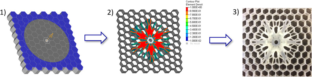
FIGURE 2. Steps of the approach for load-path optimized design of AM sandwich (after (Schwenke and Krause, 2020)).
In the first step the FE-model with the boundary conditions is defined, in the second step the optimization and design derivation take place and in the third step the additive manufacturing and the analysis of the design is performed in a practical test.
In the medical technology the use of additive manufacturing has greatly increased over the recent years. This includes the manufacturing of medical training models, which are an excellent possibility to train medical staff as well as to perform quality assurance. Physical medical patient models raining from simulators to phantoms, being used in medical imaging, are becoming more and more evolved thanks to additive manufacturing. This is due to the high geometrical freedom and the flexibility the production offers. Giving users the possibility to produce patient-based or even patient individualized models.
A standardized individualization process for a medical AM model can be seen in Figure 3 (Spallek et al., 2019). A data sets of the anatomical structures are first generated using medical imaging modalities, like computer tomographic (CT) or magnetic resonance imaging (MRI). After data acquisition, the data is segmented and model specifications, such as suitable interfaces, are designed. This is followed by post-processing, such as the removal of support structures and/or UV oven curing. Afterwards the AM model can used in the designated application. This process can be applied to all kind of anatomical AM models used for medical training and quality assurance. The process is shown in Figure 3 for generating individual patient aneurysms. This can also be applied to aortic models, ischemic stroke and stenosis (vascular constrictions) models (see Section 3.2). All models can be used in a realistic working environment under realistic treatment protocols and with medical tools. The development of a geometric and a functional model will be explained with one example each in Section 3.2.1, which are designed for the medical training model described in Section 2.4.
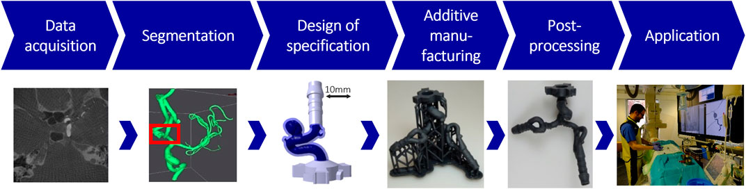
FIGURE 3. Standardized individualization process of patient-specific aneurysm models (Spallek et al., 2019)
To enable a proper quality assurance and study new approaches in radiotherapy phantoms, with tissue equivalent properties are needed (Wegner et al., 2020). The key to a phantom is the tissue-equivalent material (also called surrogate), which has different properties corresponding to medical imaging modality used. To manufacture phantoms for medical imaging AM can be used for directly printing the material (Silvestro et al., 2020; Wegner et al., 2020). But there are limitations especially when the imaging properties require properties that can’t at the moment be fulfilled by AM. The other option is to produce us AM indirectly via fabricating a AM mold, which is then filled with a tissue equivalent material (Wegner et al., 2021a; 2021b). An example of an AM mold and dissolvable AM core to manufacture a shell for a bladder phantom will be shown in Section 3.2.1. Another example where an AM prostate mold is filled with a tissue equivalent for ultrasound and MRI will be also given in Section 3.2.1.
The Hamburg Anatomical Neurointerventional Simulator, short HANNES, is a physical blood circulation model that enables the simulation of neurovascular diseases with real treatment instruments. HANNES has been used for training and research in aneurysm treatment since 2015. For this purpose, HANNES was embedded in an experimental, realistic clinical environment at the Hermann Zeumer Laboratory (HZL) of the Medical Center Hamburg-Eppendorf (see Figure 4).
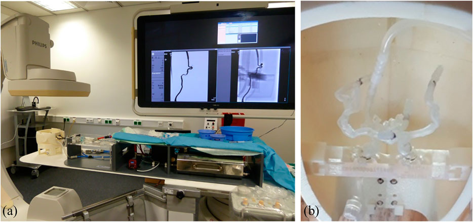
FIGURE 4. HANNES (A) in the clinical environment at the UKE, (B) enlargement of the anatomical blood vessel model in the head (Wortmann et al., 2022)
HANNES has a modular design, so that a large number of disease cases can be mapped with this model and the connection of different blood vessel model variants or patient-specific blood vessel models is possible. The base frame, the control unit, the fluid system, the abdominal parts of the aorta and the skull base are standard parts that form the platform of HANNES. The focus is on the blood vessel system, which is represented anatomically correct from the femoral artery to the head using original medical imaging data and AM (Spallek et al., 2019). The structure of the model is represented in Figure 5.
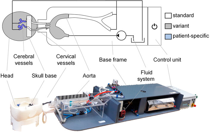
FIGURE 5. Structure of the Hamburg Anatomical Neurointerventional simulator (HANNES) (Laukotka et al., 2020)
The change of the different vessel sections at the aortic arch, at the neck arteries as well as at the blood vessels at the head is possible via defined interfaces and specially developed adapters (Spallek and Krause, 2019) (Spallek and Krause 2019).
The approaches for the application of additive manufacturing in the fields of aviation and medical technology as described in Section 2 are in this section applied to different examples. First two examples in the aviation field (Section 3.1) and then two examples for medical technology (Section 3.2) are given.
In the first example the design of an aircraft cabin partition is described using the Direct Energy Deposition process. Material selection as well as different structural concepts are presented in Section 3.1.1. Secondly the optimization of load introduction points directly integrated into the sandwich structure is described. A new test setup for the pull-out test and the corresponding results for two designs are shown in Section 3.1.2.
In the first application example, an additively manufactured aircraft cabin partition is discussed. The design process follows the approach shown in Section 2.1. The Direct Energy Deposition process is chosen as the manufacturing method, since it has the least space restrictions. However, the achievable accuracies are weak compared to other additive techniques and the material behavior is characterized by strongly anisotropic behavior (Carroll et al., 2015; Wang et al., 2016; Wolff et al., 2017). Consequently, in a first step, the material parameters of potential materials were investigated. The results can be found in (Dambietz et al., 2021). The entire component is first analyzed via the upper path.
For this purpose, the component orientation, the required functional area, functional requirements and the existing process properties are determined or considered at the beginning. By topology optimization, the functional areas are connected in compliance with defined restrictions. The results of a performed optimization are described in the next paragraph. Where the upper and lower path meet, the models are validated by the lower path.
In this section, the substructures can be tested in component tests which are described in (Hartwich et al., 2022). Figure 6 shows optimization results of the aircraft cabin partition at different volume fractions. In the results shown, an isotropized version of the material 1.4057/X17CrNi16-2 was used. An orientation lying on the base plate was chosen as the component orientation, since this can be finished safely. Overhang angles were also not allowed. The optimization objective is to minimize compliance, and all load cases from the CS-25 (European Aviation Safety Agency, 2007) were considered. Included in Figure 6 are the maximum stress, maximum deflection, and mass.
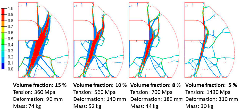
FIGURE 6. Structural concepts with different volume fractions.
The maximum allowable stress for the selected material in the present case is 518 MPa in the weakest material orientation. In all other orientations, the allowable stress is above 700 MPa. Therefore, a volume fraction of 8% is chosen. Further stress peaks can be reduced by post-processing. With an estimated mass of about 44 kg, the design is significantly lighter than existing partitions, which are about 60 kg (Nagy et al., 2018). The present design was subsequently reworked so that notches are rounded out and all load introduction points are connected to the structure.
The method used in this section is the design approach described in Section 2.2. A problem that arises when using the boundary conditions of standardized component tests is that, for example, the circular clamping of the pull-out test restricts the size of the design space. If the design space becomes larger than the clamping area, a support under the fixture is formed in the optimization, which means that the structure is not optimized for real application. This is shown as an example in Figure 7.
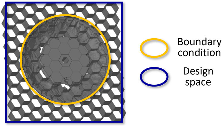
FIGURE 7. Emerging support under the clamping with a larger design space.
In this paper, the possibility of changing the test boundary conditions is investigated. Since in reality the sandwich structure is usually supported at its corners, the new test setup uses a fixture with an octagonal cut-out so that the sandwich specimen is restrained only at the four corners. The design space for optimization can then be extended to the complete sandwich structure. With this adapted test setup, the optimized structure from the standard pull-out test is compared with the new optimized structure for these boundary conditions. The two designs have the same mass and are additively manufactured with the stereolithography printer Form 3 (Formlabs) from a photopolymer synthetic resin (Clear Resin FLGPCL02). They are shown together with the new clamping and the results of the pull-out test in Figure 8.
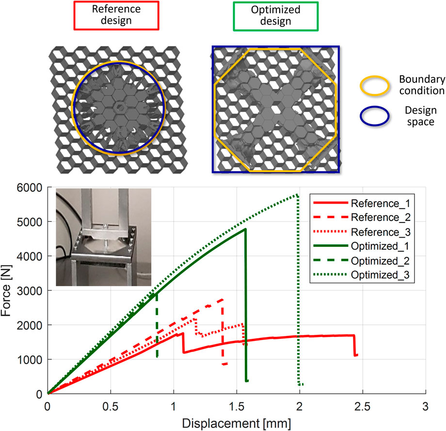
FIGURE 8. Tested designs and results in force-displacement diagram.
For each design three sandwich specimens are tested. The force-displacement diagram shows good agreement in the stiffnesses of the samples for each design, with the optimized design being noticeably stiffer. There is a large variation in the maximum force for both designs, but all the maximum forces of the optimized design are greater than those of the reference design. The stiffness and maximum force values achieved for the six specimens are shown in Table 1.
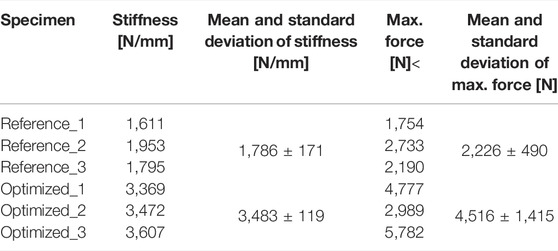
TABLE 1. Test results for stiffness and maximum force.
The optimized design performs 95% better than the old design in terms of average stiffness and 103% better in terms of maximum force. Since in the optimized design there is a strongly defined direct connection to the supported corners due to the small sandwich specimen, a verification on larger sandwich structures is necessary.
In the first example a stroke simulation model is described and the development of a modular aortic model as well as functional stenose models are shown in Section 3.2.1. Secondly the development and implementation of AM molds for medical phantoms are described in Section 3.2.2 with two examples. One using a dissolvable AM core to generate a deformable bladder shell and one using a multi-part mold to cast a prostate with integrated anatomical abnormalities.
In the BMBF-funded project COSY-SMILE (Completely Synthetic Stroke Model for Interventional Development and Education), the HANNES platform is used to simulate stroke treatments Wortmann et al., 2019. The main extension components are shown in Figure 9.
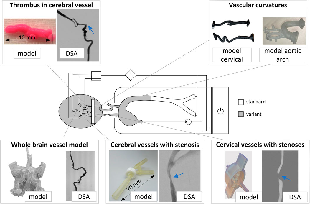
FIGURE 9. Key enhancement components for the HANNES-Stroke Model for stroke treatment (Spallek et al., 2020)
A stroke is caused by a blood clot, a so-called thrombus, stuck in the vessels. This must be removed by means of an endovascular, catheter-based procedure called thrombectomy. Frequently, vascular stenoses occur during this treatment, which can be a reason for thrombus or can hinder the treatment path of such a thrombus. Accordingly, such vascular stenoses are treated by the catheter-based procedure of percutaneous transluminal angioplasty (PTA). Treatments are performed under a Digital Subtraction Angiography (DSA) to visualize the vessels under X-ray (Wortmann et al., 2022).
For the generation of the models, the Stereolithography (SLA) is used as an additive manufacturing process for model creation. This process has been shown to be particularly suitable for reproducing blood vessels (Spallek and Krause, 2016). Since the research group has the Form2 and Form3 SLA printers from Formlabs, Sommerville, United States, these are used for model production. The principle is that a synthetic resin is cured point by point by a UV laser. The build platform is lifted from the resin bath layer by layer so that the model builds up overhead (Gebhardt, 2016). The curved vessel models and the whole-brain vessel model are predominantly anatomic models that primarily represent the geometric properties, but are also intended to be realistic in haptics and imaging and thus in material properties. In contrast, thrombi and stenoses are models that show functional behavior. For example, the thrombi should be able to fragment during treatment, while the stenoses should exhibit opening behavior. The design and manufacturing of specific models is briefly described below.
The development and manufacturing of the aorta was described in Wortmann et al., 2021a. The goal was to develop a modular aorta to simulate different anatomies using the model. Three different types of aortic arches were targeted, which are characterized by different curvatures and thus by different levels of difficulty in training. Based on the requirements defined with the physicians, such as transparency of the models, elasticity and realistic friction on the catheter, the design was started. The CT imaging data of the type II aortic arch was first segmented in the program Meshmixer, Autodesk., United States, and revised with respect to defects. This was followed by reconstruction in the CAD program CATIA V5, Dassault Systemes SA, France, to create a hollow body with a wall thickness of 2 mm from the solid model. The existing HANNES adapters were added to the supraaortal slopes in CAD. For the connection to the thoracic aorta downstream of the body, new adapters were developed that also allow an edge-free transition of the model parts. Different manufacturing options (e.g., direct vs indirect), different AM processes, and different materials were tested. An evaluation with different criteria showed that the production with SLA on the Formlabs Form3 is advantageous for the research group. For the final elaboration of the model, the installation space of the Form3 printer of 145 × 145 × 185 mm must be respected. Using the Preform software from the Formlabs company, the model was arranged on the build platform and provided with support structures. The Elastic Resin material was selected and printing on the printer was started. The printing time was approximately 30 h. For post-processing, the model was washed in 90% isopropanol (IPA), dried and cured in a UV oven (Wortmann et al., 2021a). Figure 10 shows some steps to the final model.
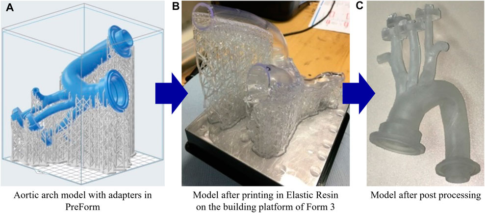
FIGURE 10. Aortic arch model in the PreForm software (Formlabs) (A), model after printing on the building platform (B), model after post processing (C).
The development and fabrication of the functional models of thrombus and stenosis were described in Wortmann et al., 2022 and Wortmann et al., 2021b. For the thrombus models, AM was only considered as a support material for agarose models for replicating calcium-rich thrombi because the material properties of many additively manufactured materials were too solid to replicate the properties of thrombi (Wortmann et al., 2022).
The goal of replicating stenoses was to have them exhibit opening behavior after treatment of the PTA and to keep the vessel model open. For this purpose, vascular models were developed that replicate a healthy vessel without stenosis. These have an area of reduced wall thickness where the stenosis is created externally by shaping (Wortmann et al., 2021a). The principle of stenosis generation is shown in Figure 11.
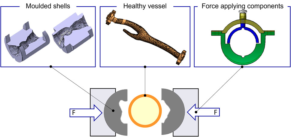
FIGURE 11. Principle for generating the stenoses in the model (Wortmann et al., 2021a).
The components were mostly additively manufactured using the Formlabs Form2/Form3 printer. The molded shells and the force applying components were created from the material Clear Resin. The vessel models were made from the materials Flexible 80 A and Elastic Resin. Depending on the concept, the force applying components were expanded with additional parts, such as snap fasteners or DualLock™ adhesives. Figure 12 shows the fabricated models using the snap fasteners concept as an example, as well as the corresponding DSA image.
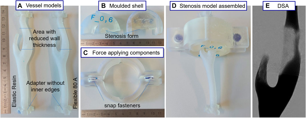
FIGURE 12. Fabricated models using the snap fasteners concept as an example (Wortmann et al., 2021b), Vessel models (A), Moulded shell (B), Force applying components (C), Stenosis model assembly (D), Digital Subtraction Angiography (E).
Prostate irradiation is a common treatment for prostate cancer. New irradiation technics try to give high doses into the tumor area while sparing the surrounding tissue as much as possible. To evaluate new treatment plans it is important to look at the prostate position during each irradiation treatment, which can for instance change due to variation in the bladder volume. For this purpose a pelvic phantom with the prostate and surrounding organs was designed (Wegner et al., 2017). To simulate the volume changes of the bladder inside this pelvic phantom a realistic deformable bladder model was needed. The development and manufacturing was described in Wegner et al., 2021b.
In order to create an anatomical urinary bladder model the process from Section 2.3 was used. Medical CT imaging data of patients was used as the basis of the model. From the imaging data, the anatomical segmentation of the bladder resulted in a volume model. The STL model of the bladder was adapted in equipped in Autodesk Inventor, Autodesk, United States with interfaces, like an opening for the filling of the bladder. The bladder wall was to be poured with a silicon with a Shore hardness of 33. Which was chosen form the elastic properties and the x-ray absorption in a CT, which can be used for a tissue of bladder wall. To define the appropriate wall thickness of the silicon bladder a simulation of the deformation was performed in Autodesk Inventor, Autodesk, United States. Boundary conditions, internal pressure and material properties were applied to the 3D model keeping the outer geometry constant while adjusting the inner surface. The deformation was compared to literature bladder deformation till a satisfactory deformation with an appropriate anatomical bladder deformation was achieved. The bladder model was subtracted from a negative mold. A core for the mold was also designed, which was later dissolved. The outer mold was split in two parts and fabricated using a stereolithography process (SLA). The SLA printer Form3 by Formlabs, Somerville, United States with a clear resin was chosen.
For the core a polyvinyl alcohol (PVA) filament was printed with a Fused Deposition Modeling (FDM) process, by using the I3 Mega S printer by Anycubic, Shenzhen, China. Inside the core a gyroid structure was chosen to promote washout (see Figure 13). After printing the outer mold and the core they are assembled as seen in Figure 13 and fixed with screws. The two-component silicon (RTV2 Shore hardness 33 by Silikonfabrik. de, Germany) was then poured inside the mold. The silicon was colored using pigment to make the flow visible in the mold. After curing the silicon at room-temperature, the mold was opened and the PVA-core was dissolved using warm water. The urinary bladder model as well as the fabrication process can be seen in Figure 13.
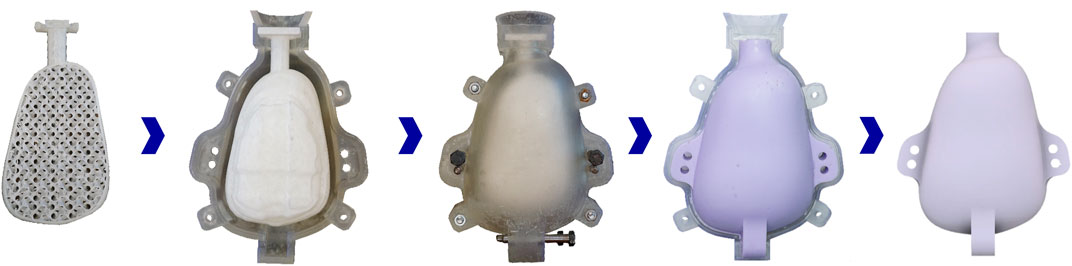
FIGURE 13. Workflow for the fabrication of a bladder model with a AM mold and core (after Spallek et al., 2020; Wegner et al., 2021b).
The deformable bladder model was integrated into a pelvic phantom for prostate irradiation (Spallek et al., 2020). Through a tube the bladder was filled with different amounts of water, ranging from 100 to 200 ml. The deformable bladder influences the position of the prostate, which is positioned bellow. This gives radiotherapy clinicians the possibility to evaluate different radiation procedures for the influences of bladder deformation and movement.
Before a radiation treatment is chosen typically a biopsy is taken from the prostate to evaluate the pathology. These biopsy samples are taken while Transrectal Ultrasound (TRUS) is performed. To integrate information for other imaging modalities in which the tumor areas can be seen a new approach is to perform a Fusion Guided Biopsy (FGB) using TRUS and MRI imaging targeting the visible MRI tumor areas. To train this procedure a is prostate phantom for FGB was developed. The implementation of the whole phantom can be found in (Spallek et al., 2020). To allow anatomically accurate imaging of the prostate as well as customizable lesions (pathological changes) inside the prostate a mold for the prostate was designed. Since biopsy cores are to be taken from the lesions within the prostate, an agarose-based starch-water mixture was chosen as a surrogate for the prostate and its lesions. The mixture has the same imaging properties as a human prostate and becomes solid, so no outer shell for the prostate model was needed. For the lesions additional additives, like salt and color pigment, that provide visibility in MRI or US, or both imaging modalities, are added. For a visual conformation of a successful targeted biopsy hit the color pigment allows visual confirmation whether the lesion was hit by the biopsy needle.
A multi-part anatomical AM mold is chosen for fabrication of the prostate. The mold consists of three levels, where a negative form of the prostate was subtracted. The process steps for the development of the anatomical prostate are as described in Section 2.3. With a patient prostate form medical imaging, in this case MRI, was used to generate the digital model. Through an intermediate plate in which lesion pins (with curves in the diameters of the lesions) can be fixed, recesses for the lesions are created (see Figure 14). This intermediate plate can be fixed on top of the first or second layer and allows through a grid an easy placement of the lesions at different positions of the prostate while also being able to include different lesion sizes. After curing of the first or second layer, the round lesion models can be placed inside the respective layer. The lesions were also cast in an additively manufactured mold, with a sphere shape and a diameter of 5 mm, 10 mm or 15 mm. All mold parts where manufactured using the SLA printer Form3 by Formlabs, Somerville, United States with a clear resin. After manufacturing the prostate was integrated into the biopsy training phantom. Imaging in MRI and TRUS show the prostate accurately and enable the training clinician to treat lesions visible in MRI and/or US (see Figures 14B,C). Due to the coloring of the lesions direct conformation of a hit can be achieved (as seen in Figure 14E).
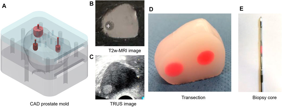
FIGURE 14. Images of the prostate mold, a fabricated prostate and a biopsy core. CAD model of the prostate casting mold (A), T2w-MRI image (B), TRUS image (C), transection of the prostate (D), biopsy core (E), ((A) Wegner et al., 2021a).
This paper examines some of the potential applications of additive manufacturing in the fields of aviation and medical technology.
Additive manufacturing processes offer a high geometric freedom of design and direct integration of load introduction points for aircraft cabin monuments. For the example of the aircraft cabin partition with an DED process it was shown that fabrication is possible. However, to ensure that the base plate and structure do not warp when material is applied, the base plate must be several millimeters thick. Therefore, in this concept, the base plate must finally be removed from the structure. This would be done by milling, for example, and would counteract any material savings through the use of additive manufacturing. Therefore, the further designs must be enforced other print orientation, where the base plate is smaller or can be better removed. One possibility would be to place it in the center of the part along the centerline. In this case, by using a turning device, heat-induced distortion can be minimized at the same time. By the optimization of load introduction points directly integrated into the sandwich structure it is shown that the boundary conditions have a direct influence on the performance. Therefore, realistic boundary conditions should be used in the test setup. To achieve an even more realistic constraint in the test setup the specimens should be directly restrained over load introduction points instead of being supported at the corners. Furthermore, a verification on larger sandwich structures is recommended.
The greatest advantage of additively manufactured medical models are the production flexibility and the geometric freedom of design offered by the manufacturing process. Resulting in models that can be adapted to specific patient anatomies (individually or generic). Based on images from medical imaging, anatomical features can be used for the design. On the one hand, AM can be used to directly produce a model, like a phantom or components of a simulator (geometric as well as functional models). But on the other hand, additive indirect manufacturing can be used to generate molds, which can be filled with tissue-equivalent mixtures. In medical imaging, this fabrication is particularly suitable for the production of soft tissues based on gel-like mixtures. Printing techniques usually only allow the fabrication of one or two different materials at a time while complex anthropomorphic models or phantoms from a single print would be the next development step in phantom manufacturing. Currently, with additional adjustments and the indirect production of molds, a variety of applications of AM models in medical training can nevertheless be demonstrated, as it was shown for the direct and indirect additive manufacturing examples in this publication.
The original contributions presented in the study are included in the article/Supplementary Material, further inquiries can be directed to the corresponding author.
All authors listed have made a substantial, direct, and intellectual contribution to the work and approved it for publication.
The authors declare that the research was conducted in the absence of any commercial or financial relationships that could be construed as a potential conflict of interest.
All claims expressed in this article are solely those of the authors and do not necessarily represent those of their affiliated organizations, or those of the publisher, the editors and the reviewers. Any product that may be evaluated in this article, or claim that may be made by its manufacturer, is not guaranteed or endorsed by the publisher.
The acknowledgements being relevant for this contribution are based on the research projects DEPOSE–Additive Fertigung von Kabinenmonumenten mittels Direct Energy Deposition (20Q1905), CabinJoint—Ganzheitliche Betrachtung und Optimierung von Verbindungselementen für die Flugzeugkabine (20Q1904B) and EFFEKT—Effiziente Kabine durch digitale Vernetzung von Technologien und Systemen (20D1927D) supported by the Federal Ministry for economic Affairs and Climate Actions (BMWK) on the basis of a decision by the German Bundestag as well as COSY-SMILE—Completely Synthetic Stroke Model for Interventional Development and Education (161L0154A) funded by the Federal Ministry of Education and Research (BMBF), CHARLIE—Entwicklung einer Methode für die Qualitätssicherung in der fokalen Strahlentherapie des Prostata-Karzinoms (03fmthh 2019) supported by the Forschungszentrum Medizintechnik Hamburg (FMTHH).
Carroll, B. E., Palmer, T. A., and Beese, A. M. (2015). Anisotropic Tensile Behavior of Ti-6Al-4V Components Fabricated with Directed Energy Deposition Additive Manufacturing. Acta Mater. 87, 309–320. doi:10.1016/j.actamat.2014.12.054
Dambietz, F. M., Hartwich, T. S., Scholl-Corrêa, J., Hoffmann, P., and Krause, D. (2021). “Influence Analysis of the Layer Orientation on Mechanical and Metallurgic Characteristics of DED Manufactured Parts,” in Lasers in Manufacturing Conference 2021, LiM 2021, 21–24 June 2021, Virtual, Online (Wissenschaftliche Gesellschaft Lasertechnik e.V.).
Department of Defense (2002). Composite Materials Handbook: Volume 3. Polymer Matrix Composites Materials Usage, Design and Analysis. Virginia: SAE International.
European Aviation Safety Agency (2007). Certification Specifications for Large Aeroplanes (CS-25). Cologne: EASA.
Fontecha Dulcey, G. (2018). Parametric, Reduced and Multiscale Model for the Interactive Optimization of Laminated Composite Structures. Bordeaux: HAL Open Science. Thesis Dissertation.
Ford, S., and Despeisse, M. (2016). Additive Manufacturing and Sustainability: an Exploratory Study of the Advantages and Challenges. J. Clean. Prod. 137, 1573–1587. doi:10.1016/j.jclepro.2016.04.150
Gebhardt, A. (2016). Additive Fertigungsverfahren: Additive Manufacturing und 3D-Drucken für Prototyping - Tooling - Produktion. München: Hanser.
Gibson, I., Rosen, D., and Stucker, B. (2015). Additive Manufacturing Technologies. New York, NY: Springer.
Hanna, M., Schwenke, J., Schwede, L.-N., Laukotka, F., and Krause, D. (2021). Model-based Application of the Methodical Process for Modular Lightweight Design of Aircraft Cabins. Procedia CIRP 100, 637–642. doi:10.1016/j.procir.2021.05.136
Hartwich, T. S., Schwenke, J., Schwan, L., and Krause, D. (2022). “Classification and Development of New Component Tests for Aircraft Cabin Interior,” in ECCM 20 – European Conference on Composite Materials, 26-30 June 2022, Lausanne, Switzerland, June 26-30, 2022 (Lausanne, Switzerland: ECCM20).
Krause, D., Schwenke, J., Gumpinger, T., and Plaumann, B. (2018). in Leichtbau. Editors H. Konstruktion, F. Rieg, R. Steinhilper, and B. Alber-Laukant (Munich, Carl Hanser Verlag: München: Hanser), 487–507.
Kumke, M. (2018). Methodisches Konstruieren von additiv gefertigten Bauteilen. Wiesbaden: Springer Fachmedien Wiesbaden.
Laukotka, F., Hartwich, T. S., Hauschild, J., Heyden, E., Schmidt, J., Schwenke, J., et al. (2020). “Entwicklung und Anwendung von Sonderprüfständen,” in Produktentwicklung und Konstruktionstechnik. Editors D. Krause, T. S. Hartwich, and C. Rennpferdt (Berlin, Heidelberg: Springer Berlin Heidelberg), 177–205. doi:10.1007/978-3-662-62393-0_8
Mitsouras, D., Liacouras, P., Imanzadeh, A., Giannopoulos, A. A., Cai, T., Kumamaru, K. K., et al. (2015). Medical 3D Printing for the Radiologist. Radiographics 35, 1965–1988. doi:10.1148/rg.2015140320
Nagy, D., Zhao, D., and Benjamin, D. (2018). “Nature-Based Hybrid Computational Geometry System for Optimizing Component Structure,” in Humanizing Digital Reality. K. de Rycke, C. Gengnagel, O. Baverel, J. Burry, C. Mueller, M. M. Nguyenet al. (Singapore: Springer Singapore), 167–176. doi:10.1007/978-981-10-6611-5_15
Ostergaard, M. G., Ibbotson, A. R., Roux, O. L., and Prior, A. M. (2011). Virtual Testing of Aircraft Structures. CEAS Aeronaut. J. 1, 83–103. doi:10.1007/s13272-011-0004-x
Ponche, R., Hascoet, J. Y., Kerbrat, O., and Mognol, P. (2012). A New Global Approach to Design for Additive Manufacturing. Virtual Phys. Prototyp. 7, 93–105. doi:10.1080/17452759.2012.679499
Ponche, R., Kerbrat, O., Mognol, P., and Hascoët, J.-Y. (2014). A Novel Methodology of Design for Additive Manufacturing Applied to Additive Laser Manufacturing Process. Robotics Computer-Integrated Manuf. 30, 389–398. doi:10.1016/j.rcim.2013.12.001
Schwenke, J., Hartwich, T., and Krause, D. (2020). “Optimierung von Inserts in Sandwichstrukturen durch additive Fertigung,” in Konstruktion für die Additive Fertigung 2018. Editors R. Lachmayer, R. B. Lippert, and S. Kaierle (Berlin, Heidelberg: Springer Berlin Heidelberg), 243–259. doi:10.1007/978-3-662-59058-4_14
Schwenke, J., and Krause, D. (2020). Optimization of Load Introduction Points in Sandwich Structures with Additively Manufactured Cores. Des. Sci. 6, 10. doi:10.1017/dsj.2020.10
Silvestro, E., Betts, K. N., Francavilla, M. L., Andronikou, S., and Sze, R. W. (2020). Imaging Properties of Additive Manufactured (3D Printed) Materials for Potential Use for Phantom Models. J. Digit. Imaging 33, 456–464. doi:10.1007/s10278-019-00257-5
Spallek, J., and Krause, D. (2017). “Entwicklung individualisierter Produkte durch den Einsatz Additiver Fertigung,” in Additive Manufacturing Quantifiziert. Editors R. Lachmayer, and R. B. Lippert (Berlin, Heidelberg: Springer Berlin Heidelberg), 69–83. doi:10.1007/978-3-662-54113-5_5
Spallek, J., and Krause, D. (2019). Medizinisches Trainingsmodell mit additiv gefertigten und individualisierbaren Gefäßmodellen: im Prüfungsverfahren. Dtsch. Patent- Markenamt.
Spallek, J., and Krause, D. (2016). Process Types of Customisation and Personalisation in Design for Additive Manufacturing Applied to Vascular Models. Procedia CIRP 50, 281–286. doi:10.1016/j.procir.2016.05.022
Spallek, J., Kuhl, J., Wortmann, N., Buhk, J.-H., Frölich, A. M., Nawka, M. T., et al. (2019). Design for Mass Adaptation of the Neurointerventional Training Model HANNES with Patient-specific Aneurysm Models. Proc. Int. Conf. Eng. Des. 1, 897–906. doi:10.1017/dsi.2019.94
Spallek, J., Wortmann, N., Kuhl, J., Wegner, M., and Krause, D. (2020). “Entwicklung und Anwendung medizinischer Simulationsmodelle,” in Produktentwicklung und Konstruktionstechnik. Editors D. Krause, T. S. Hartwich, and C. Rennpferdt (Berlin, Heidelberg: Springer Berlin Heidelberg), 255–272. doi:10.1007/978-3-662-62393-0_11
Wang, Z., Palmer, T. A., and Beese, A. M. (2016). Effect of Processing Parameters on Microstructure and Tensile Properties of Austenitic Stainless Steel 304L Made by Directed Energy Deposition Additive Manufacturing. Acta Mater. 110, 226–235. doi:10.1016/j.actamat.2016.03.019
Wegner, M., Gargioni, E., and Krause, D. (2021a). “Einsatzmöglichkeiten der additiven Fertigung in der Herstellung von Phantomen,” in Konstruktion für die Additive Fertigung 2020. Editors R. Lachmayer, K. Rettschlag, and S. Kaierle (Berlin, Heidelberg: Springer Berlin Heidelberg), 267–282. doi:10.1007/978-3-662-63030-3_14
Wegner, M., Gargioni, E., and Krause, D. (2021b). Indirectly Additive Manufactured Deformable Bladder Model for a Pelvic Radiotherapy Phantom. Trans. AMMM 3, 498. doi:10.18416/AMMM.2021.2109498
Wegner, M., Spallek, J., Kaul, M., Mittag, M., and Gargioni, E. (2017). Development of a Tissue-Equivalent Phantom for Multimodal Imaging of the Prostate. Biomed. Eng./Biomed. Tech. 62, 246. doi:10.1515/bmt-2017-5045
Wegner, M., Spallek, J., Krause, D., and Gargioni, E. (2020). Comparing Technologies of Additive Manufacturing for the Development of Modular Dosimetry Phantoms in Radiation Therapy. Trans. AMMM 2, 1. doi:10.18416/AMMM.2020.2009028
Wolff, S. J., Lin, S., Faierson, E. J., Liu, W. K., Wagner, G. J., and Cao, J. (2017). A Framework to Link Localized Cooling and Properties of Directed Energy Deposition (DED)-processed Ti-6Al-4V. Acta Mater. 132, 106–117. doi:10.1016/j.actamat.2017.04.027
Wortmann, N., Andersek, T., Guerreiro, H., Kyselyova, A. A., Frölich, A. M., Fiehler, J., et al. (2022). Development of Synthetic Thrombus Models to Simulate Stroke Treatment in a Physical Neurointerventional Training Model. All Life 15, 283–301. doi:10.1080/26895293.2022.2046181
Wortmann, N., Frölich, A. M., Kyselyova, A. A., De Sousa Guerreiro, H. I., Fiehler, J., and Krause, D. (2021a). “Aortic Model in a Neurointerventional Training Model - Modular Design and Additive Manufacturing,” in Industrializing Additive Manufacturing, 1-5 November 2021, Virtual, Online. Editors M. Meboldt, and C. Klahn (Cham: Springer International Publishing), 437–454. doi:10.1007/978-3-030-54334-1_31
Wortmann, N., Guerreiro, H., Kyselyova, A., Frölich, A. M., Fiehler, J., and Krause, D. (2021b). “Development and Manufacturing of Cervical Stenosis Models for the Integration into a Neurointerventional Simulation Model,” in Proceedings of the ASME 2021: International Mechanical Engineering Congress and Exposition (IMECE2021). doi:10.1115/imece2021-71030
Wortmann, N., Spallek, J., Kyselyova, A. A., Frölich, A. M., Fiehler, J., and Krause, D. (2019). Concept of an In-Vitro Model for Endovascular Stroke Treatment Using Additive Manufacturing. Trans. Addit. Manuf. Meets Med. 1, 82. doi:10.1017/dsi.2019.82
Keywords: additive manufactuing, medical technologies, development process, medical models, sandwitch panel, aviation and aerospace, load introduction, medical phantoms
Citation: Wegner M, Hartwich TS, Heyden E, Schwan L, Schwenke J, Wortmann N and Krause D (2022) New Trends in Aviation and Medical Technology Enabled by Additive Manufacturing. Front. Manuf. Technol. 2:919738. doi: 10.3389/fmtec.2022.919738
Received: 13 April 2022; Accepted: 06 May 2022;
Published: 23 June 2022.
Edited by:
Samyeon Kim, Jeonju University, South KoreaReviewed by:
Sang-In Park, Incheon National University, South KoreaCopyright © 2022 Wegner, Hartwich, Heyden, Schwan, Schwenke, Wortmann and Krause. This is an open-access article distributed under the terms of the Creative Commons Attribution License (CC BY). The use, distribution or reproduction in other forums is permitted, provided the original author(s) and the copyright owner(s) are credited and that the original publication in this journal is cited, in accordance with accepted academic practice. No use, distribution or reproduction is permitted which does not comply with these terms.
*Correspondence: Marie Wegner, bWFyaWUud2VnbmVyQHR1aGguZGU=
Disclaimer: All claims expressed in this article are solely those of the authors and do not necessarily represent those of their affiliated organizations, or those of the publisher, the editors and the reviewers. Any product that may be evaluated in this article or claim that may be made by its manufacturer is not guaranteed or endorsed by the publisher.
Research integrity at Frontiers
Learn more about the work of our research integrity team to safeguard the quality of each article we publish.