 Petra Wiederkehr
 Adina Grimmert2*
 Ines Heining
94% of researchers rate our articles as excellent or good
Learn more about the work of our research integrity team to safeguard the quality of each article we publish.
Find out more
METHODS article
Front. Manuf. Technol., 23 January 2023
Sec. Precision Engineering
Volume 2 - 2022 | https://doi.org/10.3389/fmtec.2022.1102140
This article is part of the Research TopicAdvances in Ultra-Precision Machining and Measurement for High-Quality Component ProductionView all 3 articles
Grinding processes are very complex due to the multitude of influencing parameters, resulting from the stochastic tool topography with numerous geometrically undefined abrasive cutting edges. Thus, the efficient design and optimization of these processes is a challenging task. Process simulations can be used as a flexible tool for analyzing interdependencies between several process parameters and identifying suitable process parameter values. For a precise process analysis, the choice of a process model with a corresponding model scale as well as the representation of optimization-relevant process effects are necessary. While macroscopic model approaches can be used to estimate the thermo-mechanical loads occurring in the contact zone, explicit modeling of the individual abrasive grains is required to predict the resulting surface topographies. In this paper, the use of simulation approaches for different scales for the analysis of different process parameters is discussed on the basis of selected application examples. The analysis of surface structuring in NC form grinding processes, e.g., was conducted by using an explicit geometric modeling of the individual abrasive grains in a geometric-physically based simulation approach to estimate wear-dependent resulting surface topographies. The parameterization of the empirical models used was based on numerical approaches for the detailed analysis of individual grain interventions. Using the complex production process of a turbine blade as an example, the utilization of a macroscopic simulation model for estimating the thermo-mechanical loads and the resulting temperatures in the workpiece during profile grinding processes is discussed.
Due to a wide variety of possible tool and process configurations as well as numerous complex influencing parameters, the design and optimization of machining processes with geometrically undefined abrasive cutting edges represent a challenging task. Various cutting materials and bond types can be used for grinding tools, which in combination with the process control and the set of process parameter values have a significant influence on the machining result. The main influencing factors include tool wear, thermal-mechanical loads, the way of supplying cooling lubricant, displacements and vibrations as well as the dressing condition of the tool. Process simulations can be used to analyze the complex interactions between these effects and to identify suitable process configurations and, thus, to design and optimize the process. For this purpose, different modeling approaches exist, which can be classified according to Brinksmeier et al. (2006) into the categories of rule based models, artificial neural net models, regression models, finite element analysis (FEA), fundamental analytical models, kinematic models and molecular dynamic models.
While numerical models such as FEA (Voronov and Ma, 2016) or molecular dynamic approaches (Rüttimann et al., 2010) provide a detailed analysis of individual grain interactions, the consideration of the complete tool topography is challenging due to its complexity and the potentially large number of cutting interactions. Geometric-physical process simulations (GPS) (Inasaki, 1996; Aurich and Kirsch, 2012; Wiederkehr et al., 2018) offer the possibility to model the complete contact zone efficiently. The models can be simplified, for example, by varying the level of detail in the modeling of the tools, e.g., by deriving surface models of the grain shapes from representative microscope images (Kuffa et al., 2016). For the approximation of physical effects, such as process forces, empirical models can be used in combination with an analysis of the geometric contact situation between the workpiece and the abrasive grain (Wiederkehr et al., 2018). Alternatively, physical effects can be modeled by using numerical models in combination with a kinematic process model (Pinto et al., 2008). For selecting and implementing a simulation of specific processes, parameters must first be identified and taken into account that have a decisive influence on the process result. Furthermore, the level of detail required for modeling the tool and workpiece has to be analyzed. In the following, exemplary simulation models are explained on the basis of selected use cases.
For the prediction of surface topographies resulting from the grinding process as well as for the detailed analysis of process forces and tool wear, an explicit consideration of individual abrasive grains on the tool surface can be used. The use of GPS represents a flexible way to do this by modeling the geometric tool and workpiece topographies to analyze the contact situation with respect to geometric parameters such as the undeformed chip thickness of the individual grains. In combination with empirical models, physical effects such as process forces or tool wear can then be modeled on the basis of these parameters. To simulate complete tool topographies and grinding processes, a stochastic model of the geometric shape of representative abrasive grains based on point clouds was developed (Wiederkehr et al., 2018; Siebrecht, 2019). By randomly distributing instances of the grain models on the surface of the simulated grinding tool, different tool shapes and sizes can be represented based on the same grain database. Figure 1 shows the model of a cylindrical grinding tool.
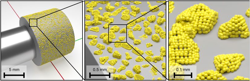
FIGURE 1. Model of a cylindrical grinding tool (grain size B181) with a diameter of d = 12 mm and a height of h = 10 mm [cf. (Wiederkehr et al., 2018)].
The GPS was used, for example, for simulation-based process design with electroplated CBN and diamond grains for surface structuring of forming tools (Wiederkehr et al., 2018; Siebrecht, 2019). In this case, the proceeding tool wear and the corresponding change in the shape of the grains were important for the simulation of the resulting surface topography. Since very detailed simulation models, for example based on FEA, are required for the simulation of single-grain wear (Wang et al., 2018), an empirical modeling approach was chosen by initially conducting experimental investigations of the wear behavior on the 5-axis machining center Deckel Maho DMU 50 eVolution using NC form grinding processes. These experiments were paused at regular intervals to digitize a defined section of the tool topography. Thus, the series of experiments provided topographical information on the tool wear progress, so that the wear related change in the shape of the abrasive grains in the digitized section could be analyzed. To validate the described simulation model, workpieces were machined and simulated experimentally. Figure 2 shows a comparison between the simulated and digitized surface topographies resulting from machining of thermally sprayed WC-Co hard coatings with a grinding tool with grain size B181 (Wiederkehr et al., 2018).
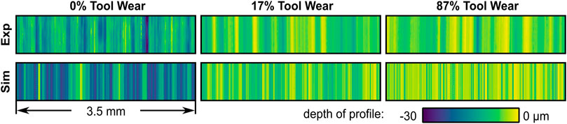
FIGURE 2. Comparison between simulated and digitized surface topographies for grinding tools with different states of wear [cf. (Wiederkehr et al., 2018)].
For the calculation of the resulting surface topographies, the consideration of effects such as tool wear and burr formation is relevant. In order to model burr formation as a result of grain engagements, a description of the plastic material flow is needed taking process-specific engagement conditions into account. For instance, the amount of material displaced by the grain and its distribution to the left and right side of the engagement area is significantly influenced by process parameters such as the undeformed chip thickness and the cutting velocity, as well as by the shape of the respective grain (Öpöz and Chen, 2012; Chen et al., 2017). An advantage of the explicit modeling of individual grains in the GPS is the ability to evaluate these process parameters individually for each grain engagement. This was used to create an empirical model, parameterized based on FEA. Of great interest are burr formations, e.g., in honing or microfinishing, due to high demands on the resulting workpiece surface (Hashimoto et al., 2016). In the following, an application scenario is presented in order to discuss the modeling of burr formations using the GPS. The process model of the simulation was adapted to take into account the superposition of workpiece rotation and simultaneous tool oscillation as a characteristic feature of microfinishing processes (Hashimoto et al., 2016). An example of a simulated honed surface is shown in Figure 3. For this, the process model of the GPS described in Section 2 was adapted to implement the process kinematics, i.e., the relative motion between the individual grains and the workpiece surface, and a force control. The cylindrical workpiece is rotated determining the cutting velocity present in the process, while the honing stone performs an oscillating motion orthogonal to the cutting direction. In terms of the individual grain, it is no longer a periodically interrupted cut due to a tool rotation, which is the case in NC-grinding processes, but rather a continuous engagement. To model the workpiece, the circumference of the workpiece surface was projected on a plane and mapped as a height field. This simplification was made because of the small curvature of the workpiece diameter of 54.2 mm in relation to the grain size D91 and infeeds in the range of a few micrometers. To consider the single grain engagements and the resulting burr formation, finite element (FE) simulations were conducted using the commercial software Abaqus/Explicit with the Coupled Eulerian Lagrangian (CEL) method as the modeling approach. The grain was assumed to be a rigid body and was generated based on a digitized diamond grain of size D91. As shown in Figure 4A, this resulted in a translatory cutting motion at a constant cutting depth or infeed. The workpiece was discretized by an Euler volume (size .08 mm × .35 mm × .1 mm) using coupled temperature-displacement elements (type EC3D8RT) for a thermomechanical analysis. The area of the model adjacent to the engagement was meshed in z-direction with a minimum element length of .5 μm. The applicability of the CEL method was demonstrated for the modeling of, e.g., orthogonal metal cutting (Ducobu et al., 2017) or single grain engagements for the parameterization of empirical process force models (Wöste et al., 2019). The material response of the workpiece was described by the constitutive material model of Johnson and Cook (Melkote et al., 2017), which was parameterized for the case of hardened steel 16MnCr5 (1.7131) (Magalhães et al., 2020), to account for the influence of strain, strain rate, and temperature on the yield stress. The contact between the grain and the material was described by Coulomb’s friction law with a coefficient of μ = .11 (Yurkov et al., 1997). Based on experimental investigations (Tilger et al., 2017), undeformed chip thicknesses of hcu = 1–5 μm and a cutting speed of vc = 2 m s−1 were selected for the simulation of single grain engagements within the FEA. Due to the rather continuous engagement of the grain during honing, the profiles of the displaced workpiece material have been extracted as soon as a steady state with an almost constant material flow was achieved. In Figure 4B, the profiles resulting from processes with different undeformed chip thicknesses after a cutting path of .16 mm are depicted. The height of the burr to the right of the engagement increases steadily with increasing undeformed chip thickness as a result of the increased cross-sectional area of the chip shape. The same can be observed on the left side up to an undeformed chip thickness of hcu = 3 μm. At larger thicknesses, an interaction of the displaced material with parts of the grain occurs above the initial workpiece surface, which strongly influences the resulting shape of the burr formation. As a result, a significant increase of the width of the burr formation can be observed while the height remains almost the same. To formulate an empirical model for burr formation, the profiles of the displaced material on the left and right of the grain engagement were each approximated using a quadratic function. This was performed for each of the five simulated grain engagements. Finally, a linear interpolation rule was established to describe the burr formation as a continuous function of the undeformed chip thickness in the GPS.
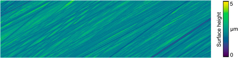
FIGURE 3. Simulated surface of a honed workpiece of an exemplary honing process.
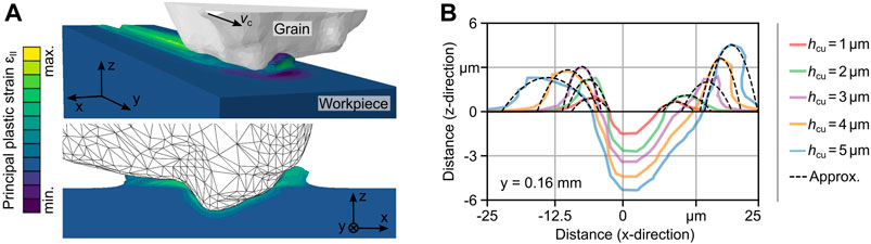
FIGURE 4. (A) FE model of the gain engagement with an undeformed chip thickness of hcu = 5 μm. (B) Cross-sectional chip shape and profiles of displaced material for different undeformed chip thicknesses and approximation of the burr formation.
To apply the results of the numerical simulation in GPS, the process model was extended accordingly. Thereby, a main challenge was the identification of the grid cells of the height field adjacent to the grain engagement, which need to be modified. Figure 5A shows an illustration of the modeling approach used to represent the burr formation in the GPS. First, an analysis of the ideal chip shape was performed with respect to the undeformed chip thickness present in order to select the corresponding approximation function, which was identified a priori with the FEA for the respective case. Based on the projection of the chip shape onto a plane in the direction of cut, the left and right limits of the engagement area orthogonal to the direction of cut and to the z-axis were then determined. For this purpose, a threshold value of .5 hcu was used for the considered process. To determine the area of the workpiece surface affected by the considered grain in the current simulation step, the potential width of the burr formation and the distance traveled by the grain in the simulation step were used as a basis. For each grid cell in this area, the distance to the respective limit of the engagement can be used to determine whether and to what extend the height value of the cell has to be adapted. For this purpose, the previously determined approximation function of the extracted profiles was evaluated.
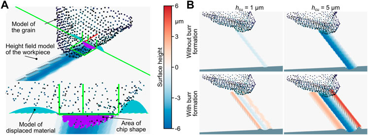
FIGURE 5. (A) Approach for modeling burr formation in the geometric physically-based simulation. (B) Results of simulated grain engagements with and without the modeling of burr formation for two different undeformed chip thicknesses.
In order to avoid aliasing effects due to averaging, cells with multiple entries present were identified. In Figure 5B, the result of an exemplary GPS of a grain engagement of a honing process is depicted. The simulation was performed for undeformed chip thicknesses of hcu = 1 μm and 5 μm. A comparison of the simulated surfaces with and without the modeling of burr formations clearly shows that the geometric shape of the displaced material determined using FEA could be reproduced with the GPS.
In grinding, the heat developed during the machining process is a major challenge due to the small chip space, a large number of simultaneous grain engagements, and the ploughing effect (Brinksmeier et al., 2006). The heat is conducted into the tool, the workpiece, the coolant and the chips, which is leading to a high thermal load (Malkin and Anderson, 1974; Yan et al., 2016; Baumgart et al., 2017). The resulting high process temperature can cause thermal damage of the workpiece surface (Malkin and Guo, 2007), changes in the microstructure of the material or of the residual stresses in the external zone (Batako et al., 2005). In creep-feed grinding, for example, high depth of cut values with ae > 4 mm and low feed rates are used (Tawakoli, 1990; VDI, 2014). Due to the high material removal rates and the long contact lengths, high mechanical and thermal loads generated during the process are acting on the workpiece. Therefore, it is necessary to investigate the thermo-mechanical strains influencing the workpiece quality. For this purpose, it is reasonable to analyze the thermo-mechanical loads of the process in a simulation system in order to avoid a damage of the workpiece which is especially important for parts like, e.g., jet engine components. In addition, thermal damage to the tool can occur (Tönshoff et al., 1992), which is accompanied by accelerated wear of the abrasive grains or the grain bond. Tool wear is especially relevant in the fine machining of functional surfaces, since the tool topography has a direct influence on the surface quality. An exemplary process used for fine machining is NC form grinding (Malkin and Anderson, 1974).
In the aerospace industry, grinding processes are an important and frequently used machining step for the production of high pressure turbine blades (hpt blades). These blades are initially manufactured from nickel-based superalloys in an investment casting process (Reed, 2006). The fir tree profile at the blade root is shown in Figure 6A. It serves as a connection between the blade and the disk mounted on the shaft in the engine. As shown in Figure 6A when comparing the cast and finished part, several millimeters of stock material have to be removed in order to manufacture the fir tree profiles. In consideration of maximizing productivity in serial production for components with a high batch volume, these profiles are usually transferred to the component with only few grinding strokes utilizing creep-feed grinding processes with porous corundum grinding wheels (Guo et al., 2003; Guo et al., 2004; Klocke et al., 2015). Since the rotating parts, such as the blades, are particularly safety relevant components of an aircraft engine, overloading of the component during the manufacturing process must be prevented. This is especially critical in the case of the hpt blades, as these are hollow components with wall thicknesses of only a few millimeters. The hollow design of the blade is necessary due to the constantly increasing demands regarding the efficiency of engines, which lead to higher turbine inlet temperatures that the blades have to withstand (Perepezko, 2009). This made the cooling of the blades necessary and, thus, cooler air from the compressor is fed through internal cooling channels of the hpt blades resulting in the hollow blade structure (Giamei, 2013). Furthermore, MTU Aero Engines AG recently introduced a flexible manufacturing system (FMS) for fully automated and parallel production of different hpt blades (Weidemann, 2022). In this FMS, each grinding center is equipped with an integrated robot that obtains the components from a high rack and clamps them in the fixtures. For short processing times and avoiding a frequent re-clamping of the component, the fixtures were designed to provide free access to as many profiles of the component that have to be ground as possible. This fixture design resulted in a component fixed as a cantilever with a high flexibility, as shown in Figure 6B. The combination of the high process forces, hollow components and the cantilevered clamping required a process design taking into account the mechanical and thermal constraints. In order to reduce the number of iterative testing cycles on the serial production machines, the planning of the process is supported by a process simulation.
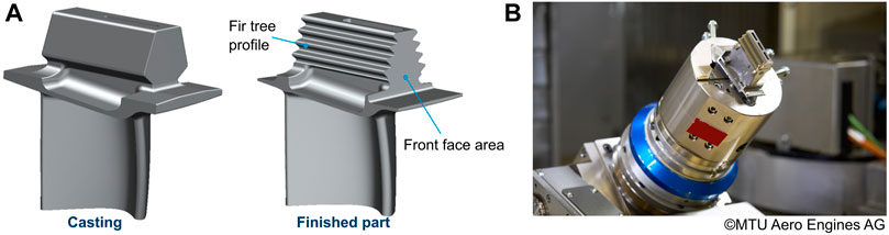
FIGURE 6. (A) Cast and finished part of an hpt blade with root profile (courtesy of MAN Energy Solutions) (Grimmert and Wiederkehr, 2021a). (B) Clamped hpt blade for grinding in the FMS (copyright: MTU Aero Engines AG).
For the described application, a macroscopic process simulation of the creep-feed grinding process was developed to predict the resulting stresses and temperatures in the workpiece. While microscopic simulation approaches describe the interactions between tool and workpiece at the single grain scale, the macroscopic approach describes the process with respect to the grinding contact zone (Brinksmeier et al., 2006). In the considered profile grinding processes, the depth of cut values and contact lengths are varying over the grinding wheel width b due to the raw part geometry and the grinding wheel shape. The grinding wheel radius, and thus the cutting speed, also change over the grinding wheel width. These parameters, which are variable over b, must be determined in the macroscopic simulation. Additionally, due to the high depth of cut values in creep-feed grinding, the material removal and the resulting inclination of the contact zone cannot be neglected if the temperature and stress distributions in the workpiece are to be analyzed (Dawson and Malkin, 1984; Rowe, 2013).
The macroscopic grinding process simulation, which is presented in more detail in (Grimmert and Wiederkehr, 2021b), was implemented in the commercial finite element (FE) software COMSOL Multiphysics. For the simulation and evaluation of the local material removal the deformed geometry module was used, taking into account the macroscopic grinding wheel shape and neglecting the individual grains and pores of the wheel. In this module, mesh displacements and velocities are defined as boundary conditions, whereupon the displacements of the remaining nodes are solved for, according to a mesh smoothing method. For the grinding simulation, the Laplace mesh smoothing method was used (COMSOL Multiphysics, 1998). The deformed geometry module is based on a calculation method only solving for the mesh displacements and not calculating any resulting strains or stresses. Therefore, a reduction of the volume of the workpiece resulting from the mesh displacements and smoothing, does not represent a compression of the material, but a reduction of the mass of the component (COMSOL Multiphysics, 1998). Thus, this approach is well suitable for modeling the removal of material. For the grinding process, the workpiece and a part of the grinding wheel were modeled and meshed. Since the grinding wheel was only used to calculate the material removal and the abrasive grains as well as the mechanical and thermal loads acting on the grinding wheel were not considered, the grinding wheel was reduced to the relevant section for the contact zone also neglecting the rotation. For the grinding wheel surface a structured mesh was generated resulting in pyramid elements, while the rest of the grinding wheel and the workpiece were meshed with tetrahedral elements. The size of the elements depends on the profile of the grinding wheel. The mesh for both, the grinding wheel and the workpiece that the profile was ground into, had to be fine enough to replicate all relevant parts of the profile, making the number of elements highly dependent on the complexity of the profile. For the grinding of a fir tree profile to a block sample of 50 mm length and 30 mm width, the mesh consisted of roughly two million elements.
As boundary conditions, the workpiece was spatially fixed and the grinding wheel was moved over the workpiece with the feed rate. For the simulation of the material removal, the vertical distance between the surface of the grinding wheel and the workpiece surface gz was calculated, which is shown in Figure 7A. As soon as gz decreased below a certain gapvalue gz,0 for a node of the workpiece surface, a vertical mesh velocity vm was applied to this node. In order to improve the convergence and avoid discontinuities, vm was multiplied with a smoothed step function. To ensure that the accepted gap did not lead to an increased material removal by gz,0, the modeled grinding wheel was positioned vertically higher by exactly this value. As an additional boundary condition, the mesh displacement in normal direction was blocked for all surfaces adjacent to the surface to be ground. Figure 7B shows the distance gz for the grinding of a fir tree profile into a block sample.
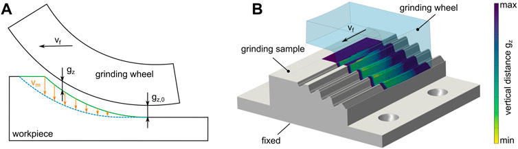
FIGURE 7. (A) Schematic representation of the distance-based simulation of material removal and (B) associated FE model with distance gz (Grimmert and Wiederkehr, 2021b).
Due to the significantly varying depth of cut values over the wheel width and the resulting mesh deformations of the surface, major mesh distortions can occur, which make an automated remeshing necessary. In the software COMSOL Multiphysics, different physical modules can be coupled. The material removal simulation in the deformed geometry module was coupled with the solid mechanics module to calculate and apply the process forces, and with the heat transfer in solids module to analyze the temperature distribution in the workpiece. Both, the force models as well as the grinding heat flux model were experimentally calibrated based on experimental grinding tests. For this purpose, a total of 120 grinding tests were conducted grinding samples made of Inconel 718 with a cylindrical Al2O3 grinding wheel. The process forces were measured on the workpiece side with a Kistler 9129AA dynamometer for all experiments, and the temperatures were measured inside the workpiece at two positions with thermocouples of type K for 40 experiments. The test matrix was created using a design of experiments varying the process parameter values, such as the depth of cut, feed rate and cutting speed.
The selection and calibration of the force models for the normal and tangential force was performed by a cross-validation and by solving an optimization problem as shown in (Grimmert and Wiederkehr, 2021c). For this purpose, different normal force models were taken from literature, including the Werner model (Werner, 1971) modified by Mishra and Salonitis (2013) and a standard model derived from different models by Tönshoff et al. (1992), and were compared with regard to their suitability for the considered parameter range. It was found that a slightly modified standard model according to Tönshoff et al. (1992) provided the best results and was, therefore, calibrated using the experimental data (Grimmert and Wiederkehr, 2021c). The tangential force was modeled by a multiple linear regression model expressing the grinding force ratio
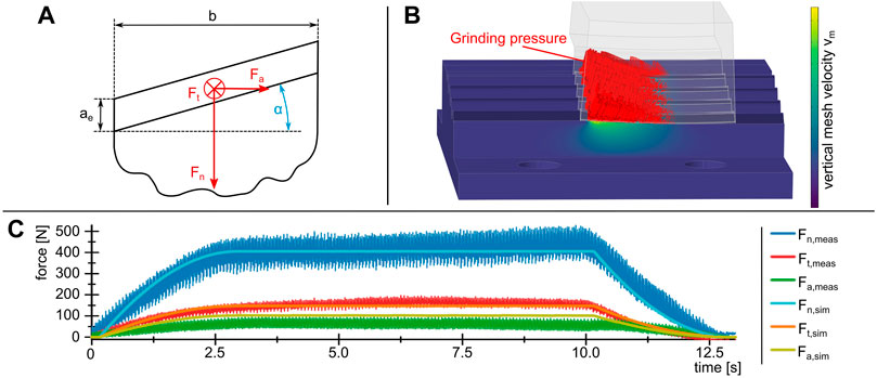
FIGURE 8. (A) Profile angle α and the resulting axial force component Fa. (B) FE model with the grinding pressure distribution in the grinding zone, and (C) the comparison of the transient measured and simulated force curves.
For the transient process simulation, the three force components were applied to the contact zone as grinding pressure, as shown in Figure 8B. The distribution of the grinding pressure over the contact length was analyzed by comparing the measured and simulated transient force curves before and after the full grinding wheel engagement. According to the results of Shi et al. (2009) and due to the good agreement between the simulated and measured data, a right triangle was used as distribution function, as shown in Figure 8B. As an additional boundary condition, the bottom of the grinding sample was spatially fixed, while all other surfaces were free. In order to validate the force prediction, a fir tree profile was ground into a block-shaped grinding sample using 12 grinding strokes with varying process parameter values. The simulated and measured transient force curves are shown for an exemplary grinding stroke in Figure 8C.
The quality of the force models was quantitatively evaluated by calculating the mean of the quasi-stationary force signals in the range of the full grinding wheel engagement for both, the simulated and the measured forces. Subsequently, the difference of these means was calculated and given as percentage. As shown for the process in Figure 8C, also the other grinding strokes showed a good agreement of the normal and tangential with an average deviation of 6.7% and 7.0%, respectively. The axial force showed a higher deviation from the measurement results with an average of 33.2%, though, this corresponded to a mean absolute error of only 26.6 N. The higher deviation of the axial force could have been caused by the negligence of the grinding wheel deflection. Further, a burr formation was observed on one side of the fir profile, which could have caused an additional axial force component.
In grinding it can be assumed that the complete grinding power is converted to heat (Rowe, 2013). The heat partition
Since the grinding power P can be calculated based on the tangential force and the cutting speed, the heat input factor ε as well as the distribution of the heat flux (x′) over the contact length lc had to be determined. For this purpose, the temperature signal of one of the two thermocouples positioned 4 mm below the unground workpiece surface was used. The two unknown quantities ε and (x′) were evaluated for each of the 40 experiments using the optimization module of the software COMSOL Multiphysics iteratively solving the FE model. For the optimization problem, the BOBYQA algorithm was used due to its stable convergence and moderate computation times (Powell, 2009). In order to determine the heat distribution, the transient temperature signal was used for the formulation of the optimization problem, whereas for the evaluation of the heat partition only the maximum temperature was used. Subsequently, an averaged distribution function was calculated based on the optimization results differentiating between up- and down-grinding, respectively. The heat partition was modeled by a multiple linear regression model in dependency of the process parameter values. The second thermocouple was then used to validate the results. It showed good results with a mean percentage error of the maximum temperature rise of 16.32%, corresponding to a mean absolute error of 23.2 K.
The representation of process temperatures in a macroscopic temperature model provides the possibility to analyze the quality of the workpiece surface. However, in order to be able to develop a temperature model also for GPS on a single-grain basis, experimental investigations of the thermo-mechanical condition on single grains in the cutting process are required (Bergs et al., 2021). The knowledge about the single grain temperature is relevant with regard to the thermal damage of single grains and, thus, the wear progress of the tool. For this purpose, a test setup for the temperature measurement on a single grain in a grinding process with the use of cooling lubricant is presented in the following. In order to measure the cutting temperature in the contact zone and thus to use it in particular for the calibration of temperature models, the cutting zone must be made accessible to the measuring equipment. Often thermocouples are used to measure process temperatures during grinding, which in some cases are themselves machined to record the surface temperature of the workpiece (Batako et al., 2005). Since the temperature distribution around the cutting zone is diffuse and thermocouples often require a long response time, this experimental setup is not suitable for determining temperatures of individual grains in the cutting zone. Due to the stochastic distribution of the grains on the tool topography, a high sampling rate is necessary to detect individual grains, since they only pass through the measuring range for a short period of time. In addition, high process temperatures are to be expected during grinding. Therefore, the quotient pyrometer Fire III from en2Aix—energy engineering Aachen GmbH was used for the temperature measurements, which can realize a high sampling rate of up to 10 MHz as well as a valid measurement results from a temperature of 250°C. Since pyrometer measurement is an optical method, the pyrometer fiber must be positioned in the cutting zone for the measurement of the cutting temperature under the influence of cooling lubricant. This experimental setup offers the potential to measure the temperature of individual grains in the cutting zone and to evaluate the cooling lubrication strategy based on qualitative temperature differences.
The experimental investigations were carried out during NC form grinding with flood cooling on the 5-axis machining center Deckel Maho DMU 50 eVolution. The material used was 100Cr6 cold work tool steel. The workpiece was also hardened to 62 HRC and the machining surface was pre machined on a Geibel & Hotz FS 635 Z CNC surface grinding machine. For the grinding operation, conical grinding tools from August Rüggeberg GmbH & Co. KG (PFERD Werkzeuge) with diamond abrasives in electroplated bond and a grit size of D91 were utilized. The minimum diameter of the tool was Dmin = 9 mm and the maximum diameter Dmax = 15 mm. The angle of the tool surface was βtool = 65°. With the pyrometer used, it is possible to measure temperatures of objects even if they do not fill the entire measurement spot (Müller and Renz, 2001). This is essential for the measurement of cutting temperatures on grinding tools, since the grains cannot completely fill the measuring area, depending on their grain size. In addition, due to the stochastic structure of the tool topography, it may be possible that only parts of individual grains cross the measuring range. Another challenge is the short period of the grain intervention. It is therefore not guaranteed that every grain, that is engaged in the measuring area was also previously engaged in the material. For the investigations, a pyrometer fiber with a diameter of Dfibre = 330 μm was applicated into the workpiece using a needle in order to prevent the fibre from damage. Thus, the measurement spot diameter corresponded to the fiber diameter. The experimental setup is shown in Figure 9A and a detailed representation of the pyrometer Fire III in Figure 9B. During cutting, the entire lateral surface of the grinding tool was engaged. The bore diameter for the pyrometer fiber in the workpiece was Dbore = 1.2 mm and the outer diameter of the needle was Dneedle = .8 mm. The spaces between the needle and the pyrometer fiber as well as between the needle and the bore were filled with the 2-component adhesive X60. The material was machined along an NC path of a length of l = 151 mm. The pyrometer fiber was machined after a path of 139 mm, so that the tool could reach a stationary state before the temperature measurement was conducted. A large overlap of the measurement object and the measurement spot had a positive effect on the strength of the measurement signal. For the temperature measurements, workpieces made of 100Cr6 (62 HRC) were machined (n = 16,000 min−1, ap = 20 μm, vf = 800 mm/min). A sampling rate of 1 MHz was used for the measurement. The tool path crossed the fiber, which was ground over at a defined height of the tool topography. In this way, the tool topography could be digitized at the corresponding area of the tool surface over the entire circumference of the tool. The temperature was calculated on the basis of the measured voltages U1 and U2 of the two photodiodes according to the manufacturer’s specifications. A measurement can be considered valid if the respective voltage of the two photodiodes of the pyrometer U1 and U2 were detected in a range of U1,2 = 1 V–10 V. Figure 10 shows an example of a valid measurement. During the measurement several grain overflows were detected. The signal strength of the measured voltages decreased as the grain moved along the NC path to the edge of the measurement range. It is assumed that the abrasive grain has the highest temperature in the measuring spot of the fiber compared to the cooling lubricant and the bond. To calculate the temperature, the analog signals of the two photodiode voltages are first adjusted by the gain factor and the system noise (en2Aix, 2022). These adjusted voltage signals are called clear voltage and are calculated as follows:
Here, U represents the measured voltage of the respective photodiode, z is the zero voltage level, and G is the gain factor of the signal input of the respective diode (en2Aix, 2022). The measurement was based on the assumption that the components under consideration behave like gray radiators. The resulting temperature was calculated on the basis of the clear voltages Uclear,1 and Uclear,2 with the polynomial of the calibration belonging to the system as follows (en2Aix, 2022):
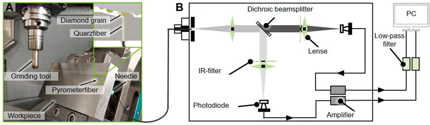
FIGURE 9. (A) Experimental setup for in situ measurement of single grain temperatures with a two-color pyrometer. (B) Schematic representation of the En2Aix fast fiber-optic two-color pyrometer Fire III (Müller and Renz, 2001).
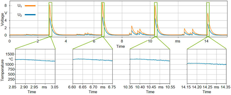
FIGURE 10. Exemplary result of a single grain temperature measurement from a grinding process.
The voltages U1 and U2 are in the valid measurement range for the sections highlighted in Figure 10. The closer the measured voltages came to the 10 V limit, the stronger the measurement signal was and the lower the noise in the measurement result of the temperature measurement. Using the measured voltages U1 and U2, the temperature curves shown in Figure 10 representing each detected overrun of the grain. The measured temperature resulted in Tgrain = 1,250°C for the first three overruns of the grain. The last detected overrun resulted in a temperature of only 1,050°C. The slightly reduced measured temperature can be explained by the fact that the grain on the NC path already engages at the edge of the measurement spot and therefore the coverage with the measuring range is no longer optimal. The evaluation of all four detected grain overruns from Figure 10 resulted in a deviation of the grain temperature of .41%.The measured temperature represents the actual process temperature detected during the cutting process. Within the scope of different measurements, which all included several grain overruns in the measurement interval, grain temperatures from Tgrain = 950°C to Tgrain = 1,250°C were obtained. The variance of Δ Tgrain = 300°C between the temperatures of different measurements resulted from the multitude of stochastic influences of the tool topography on the machining process. In this context, not only the stochastic distribution of the grains, but also their varying topography are reasons for different heat development at the individual grain in the machining process. In future investigations, this knowledge will serve for calibrating temperature models on the basis of individual grains in order to model the process temperature in the simulation system. For this purpose, the measured grain temperature must be investigated in correlation with the tool topography in the GPS. In this way, not only the influence of the tool wear on the resulting forces, but also on the resulting temperature development at the single grain should be simulated. At the same time, the wear history of selected grains can be investigated under consideration of the measured cutting temperature. The measurement of individual grain temperatures also enables a qualitative assessment of the cooling lubrication strategy and optimization of the use of cooling lubricant in order to make the machining process more sustainable.
Due to the high complexity and the various influencing factors in abrasive processes, the analysis and design of these processes represents a major challenge. In this article, several application scenarios were discussed to show how process simulations can be used to analyze abrasive processes. Since different effects are significantly relevant for the analysis and optimization objective depending on the application, different simulation approaches and model scales were applied. Using the example of the geometric-physical modeling of grinding tools taking into account the explicit geometric shape of the individual grains, the resulting surface topographies resulting from NC form grinding processes with electroplated bonded grinding pins in different wear states can be analyzed. While this modeling approach allows for a consideration of the entire grinding tool topographies over larger process areas, a FE model of a single grain engagement was used to show the possibility of considering the plastic material behavior so that the occurring burr formation in a honing process can be calculated as a function of the engagement situation. To be able to transfer these detailed considerations from the numerical model to complete processes, a combination of this approach with the geometric-physical process model on a single grain basis was presented, so that the burr formation could also be modeled in the GPS. In future investigations, an extension of this application to complete honing processes is intended taking into account the grain wear and the force control of the process. In particular, changes in material properties resulting from plastic deformation as well as the influence of the burr formation on subsequent grain interactions are to be taken into account.
The possibility of predicting process forces and temperatures by means of an experimentally calibrated macroscopic process simulation was presented using the example of creep feed grinding processes for the manufacturing of hpt blades. The locally varying engagement conditions in profile grinding processes were evaluated in an FE model and, in addition to the process parameters, served as input variables for the modeling of the thermo-mechanical load situation in the contact zone. By coupling the material removal simulation with the corresponding loads in the FE model, the effects of the process on the workpiece can be analyzed. The predictability of the thermo-mechanical load in the contact zone provides a good basis for the future planned extension of the simulation to include models of the resulting edge zone properties of the component. Finally, a measurement approach using a fiber-optic two-color pyrometer was presented, which offers the potential to measure process temperatures at the grain-workpiece contact zone by machining the fiber in the grinding process. This provides a promising application for the parameterization of thermo-mechanical simulation models.
The datasets presented in this article are not readily available because data generated at MTU is subject to the obligation of secrecy. Requests to access the datasets should be directed to AG, YWRpbmEuZ3JpbW1lcnRAbXR1LmRl.
All authors of this article have made significant scientific contributions to this work, reviewed the text and approved it for publication.
The investigations on the geometric-physical grinding process simulation on a single grain basis and on the burr formation modeling were funded by Deutsche Forschungsgemeinschaft (DFG)—Projektnummern 324889278 and 450792335 (Gefördert durch die Deutsche Forschungsgemeinschaft (DFG)—Projektnummern 324889278 and 450792335). The development of the simulation model for the production of high-pressure turbine blades was funded by the Aeronautics Research Program VI (LuFo-VI) as part of the “InvernTurb” project—project number 20D1920A.
Author(s) AG was employed by MTU Aero Engines AG.
The remaining authors declare that the research was conducted in the absence of any commercial or financial relationships that could be construed as a potential conflict of interest.
All claims expressed in this article are solely those of the authors and do not necessarily represent those of their affiliated organizations, or those of the publisher, the editors and the reviewers. Any product that may be evaluated in this article, or claim that may be made by its manufacturer, is not guaranteed or endorsed by the publisher.
Aurich, J., and Kirsch, B. (2012). Kinematic simulation of high-performance grinding for analysis of chip parameters of single grains. CIRP J. Manuf. Sci. Technol. 5 (3), 164–174. doi:10.1016/j.cirpj.2012.07.004
Batako, A., Rowe, W., and Morgan, M. (2005). Temperature measurement in high efficiency deep grinding. Int. J. Mach. tools Manuf. 45 (11), 1231–1245. doi:10.1016/j.ijmachtools.2005.01.013
Baumgart, C., Radziwill, J. J., Kuster, F., and Wegener, K. (2017). A study of the interaction between coolant jet nozzle flow and the airflow around a grinding wheel in cylindrical grinding. Procedia CIRP 58, 517–522. doi:10.1016/j.procir.2017.03.261
Bergs, T., Röttger, J., Barth, S., and Prinz, S. (2021). Approach to the numerical modelling of the chip temperatures in single grain scratching. Prod. Eng. 15 (3-4), 451–455. doi:10.1007/s11740-021-01017-7
Brinksmeier, E., Aurich, J. C., Govekar, E., Heinzel, C., Hoffmeister, H.-W., Klocke, F., et al. (2006). Advances in modeling and simulation of grinding processes. CIRP Ann. 55 (2), 667–696. doi:10.1016/j.cirp.2006.10.003
Carslaw, H. S., and Jaeger, J. C. (1959). Conduction of heat in solids. 2nd Edition. Oxford: Oxford University Press.
Chen, X., Öpöz, T., and Oluwajobi, A. (2017). Analysis of grinding surface creation by single-grit approach. J. Manuf. Sci. Eng. 139, 12. doi:10.1115/1.4037992
Dawson, P. R., and Malkin, S. (1984). Inclined moving heat source model for calculating metal cutting temperatures. J. Eng. Industry 106 (3), 179–186. doi:10.1115/1.3185930
Ducobu, F., Arrazola, P.-J., Rivière-Lorphèvre, E., Zarate, G. O., Madariaga, A., and Filippi, E. (2017). The CEL method as an alternative to the current modelling approaches for Ti6Al4V orthogonal cut-ting simulation. Procedia CIRP 58, 245–250. doi:10.1016/j.procir.2017.03.188
en2Aix (2022). en2Aix – energy engineering Aachen GmbH. Pyrometer Fire-3 Handbuch. Available at: https://en2aix.de/.
Giamei, A. F. (2013). Development of single crystal superalloys: A brief history. Adv. Mater. Process. 171, 26–30.
Grimmert, A., and Wiederkehr, P. (2021c). Experimental study on macroscopic force modelling for surface grinding processes in aerospace industry. Procedia CIRP 101, 146–149. doi:10.1016/j.procir.2020.11.007
Grimmert, A., and Wiederkehr, P. (2021a). Indirect force measurement using spindle currents for grinding processes in aerospace industry. SSRN Electron. J., MIC Procedia 082–088. doi:10.2139/ssrn.3936424
Grimmert, A., and Wiederkehr, P. (2021b). Macroscopic process simulation of surface and profile grinding processes estimating forces for the production of turbine blades. Procedia CIRP 102, 126–131. doi:10.1016/j.procir.2021.09.022
Guo, C., Campomanes, M., Mcintosh, D., Becze, C., Green, T., and Malkin, S. (2003). Optimization of continuous dress creep-feed form grinding process. CIRP Ann. 52 (1), 259–262. doi:10.1016/s0007-8506(07)60579-4
Guo, C., Campomanes, M., Mcintosh, D., Becze, C., and Malkin, S. (2004). Model-based monitoring and control of continuous dress creep-feed form grinding. CIRP Ann. 53 (1), 263–266. doi:10.1016/s0007-8506(07)60694-5
Hashimoto, F., Yamaguchi, H., Krajnik, P., Wegener, K., Chaudhari, R., Hoffmeister, H.-W., et al. (2016). Abrasive fine-finishing technology. CIRP Ann. 65 (2), 597–620. doi:10.1016/j.cirp.2016.06.003
Inasaki, I. (1996). Grinding process simulation based on the wheel topography measurement. CIRP Ann. 45 (1), 347–350. doi:10.1016/s0007-8506(07)63077-7
Klocke, F., Soo, S. L., Karpuschewski, B., Webster, J. A., Novovic, D., Elfizy, A., et al. (2015). Abrasive machining of advanced aerospace alloys and composites. CIRP Ann. 64 (2), 581–604. doi:10.1016/j.cirp.2015.05.004
Kuffa, M., Züger, S., Kuster, F., and Wegener, K. (2016). A kinematic process model and Investigation of surface roughness for high efficiency dry grinding. Procedia CIRP 46, 636–639. doi:10.1016/j.procir.2016.04.007
Magalhães, F., Ventura, C., Abrão, A., and Denkena, B. (2020). Experimental and numerical analysis of hard turning with multi-chamfered cutting edges. J. Manuf. Process. 49, 126–134. doi:10.1016/j.jmapro.2019.11.025
Malkin, S., and Anderson, R. (1974). Thermal aspects of grinding: Part 1–Energy partition. J. Eng. Ind. 96 (4), 1177–1183. doi:10.1115/1.3438492
Malkin, S., and Guo, C. (2007). Thermal analysis of grinding. CIRP Ann. 56 (2), 760–782. doi:10.1016/j.cirp.2007.10.005
Melkote, S. N., Grzesik, W., Outeiro, J., Rech, J., Schulze, V., Attia, H., et al. (2017). Advances in material and friction data for modelling of metal machining. CIRP Ann. 66 (2), 731–754. doi:10.1016/j.cirp.2017.05.002
Miao, Q., Li, H. N., and Ding, W. F. (2020). On the temperature field in the creep feed grinding of turbine blade root: Simulation and experiments. Int. J. Heat Mass Transf. 147, 118957. doi:10.1016/j.ijheatmasstransfer.2019.118957
Mishra, V. K., and Salonitis, K. (2013). Empirical estimation of grinding specific forces and energy based on a modified werner grinding model. Procedia CIRP 8, 287–292. doi:10.1016/j.procir.2013.06.104
Müller, B., and Renz, U. (2001). Development of a fast fiber-optic two-color pyrometer for the temperature measurement of surfaces with varying emissivities. Rev. Sci. Instrum. 72 (8), 3366–3374. doi:10.1063/1.1384448
Öpöz, T., and Chen, X. (2012). Experimental investigation of material removal mechanism in single grit grinding. Int. J. Mach. Tools Manuf. 63, 32–40. doi:10.1016/j.ijmachtools.2012.07.010
Perepezko, J. H. (2009). The hotter the engine, the better. Science 326 (5956), 1068–1069. doi:10.1126/science.1179327
Pinto, F., Vargas, G., and Wegener, K. (2008). Simulation for optimizing grain pattern on engineered grinding tools. CIRP Ann. 57 (1), 353–356. doi:10.1016/j.cirp.2008.03.069
Reed, R. C. (2006). The superalloys: Fundamentals and applications. New York, NY: Cambridge University Press.
Rowe, W. B., and Jin, T. (2001). Temperatures in high efficiency deep grinding (HEDG). CIRP Ann. 50 (1), 205–208. doi:10.1016/S0007-8506(07)62105-2
Rüttimann, N., Buhl, S., and Wegener, K. (2010). Simulation of single grain cutting using SPH method. J. Mach. Eng. 10 (3), 17–29.
Saljé, E., Damlos, H.-H., and Teiwes, H. (1981). Problems in profile grinding — angular plunge grinding and surface grinding. CIRP Ann. 30 (1), 219–222. doi:10.1016/s0007-8506(07)60929-9
Shi, Z., Attia, H., and Srinivasaraghavan, M. (2009). Experimental investigations of the force distributions in the grinding contact zone. Mach. Sci. Technol. 13 (3), 372–384. doi:10.1080/10910340903237889
Siebrecht, T. (2019). Simulation von NC-Formschleifprozessen zur Vorhersage von Oberflächentopographien unter Berücksichtigung des Werkzeugverschleißes. Dortmund: Diss. TU Dortmund.
Tawakoli, T. (1990). Hochleistungs-Flachschleifen: Technologie, Verfahrensplanung und wirtschaftlicher Einsatz. Bremen: Diss. Universität Bremen.
Tilger, M., Siebrecht, T., and Biermann, D. (2017). Fundamental investigations of honing processes related to the material removal mechanisms. Aachen, Germany: WGP-Jahreskongress, Apprimus, 121–127.
Tönshoff, H. K., Peters, J., Inasaki, I., and Paul, T. (1992). Modelling and simulation of grinding processes. CIRP Ann. 41 (2), 677–688. doi:10.1016/s0007-8506(07)63254-5
Voronov, S., and Ma, W. (2016). Simulation of chip-formation by a single grain of pyramid shape. Vibroengineering Procedia 8, 39–44.
Wang, J., Yu, T., Ding, W., Fu, Y., and Bastawros, A. F. (2018). Wear evolution and stress distribution of single CBN superabrasive grain in high-speed grinding. Precis. Eng. 54, 70–80. doi:10.1016/j.precisioneng.2018.05.003
Weidemann, T. (2022). Automatisierte Schaufelfertigung auf dem Weg zur Smart Facotry. Hrsg. von MTU Aero Engines AG. Available at: https://aeroreport.de/de/innovation/automatisierte-schaufelfertigung-auf-dem-weg-zur-smart-factory.
Wiederkehr, P., Siebrecht, T., and Potthoff, N. (2018). Stochastic modeling of grain wear in geometric physically-based grinding simulations. CIRP Ann. 67 (1), 325–328. doi:10.1016/j.cirp.2018.04.089
Wöste, F., Siebrecht, T., Fast, M., and Wiederkehr, P. (2019). Geometric physically-based and numerical simulation of NC-grinding processes for the calculation of process forces. Procedia CIRP 86, 133–138. doi:10.1016/j.procir.2020.01.022
Yan, P., Rong, Y., and Wang, G. (2016). The effect of cutting fluids applied in metal cutting process. Proc. Institution Mech. Eng. Part B J. Eng. Manuf. 230 (1), 19–37. doi:10.1177/0954405415590993
Yurkov, A., Skvortsov, V., Buyanovsky, I., and Matvievsky, R. (1997). Sliding friction of diamond on steel, sapphire, alumina and fused silica with and without lubricants. J. Mater. Sci. Lett. 16 (16), 1370–1374.
Keywords: grinding, simulation, profile grinding, temperature measurement, creep feed grinding, NC form grinding
Citation: Wiederkehr P, Grimmert A, Heining I, Siebrecht T and Wöste F (2023) Potentials of grinding process simulations for the analysis of individual grain engagement and complete grinding processes. Front. Manuf. Technol. 2:1102140. doi: 10.3389/fmtec.2022.1102140
Received: 18 November 2022; Accepted: 28 December 2022;
Published: 23 January 2023.
Edited by:
Panagiotis Kyratsis, University of Western Macedonia, GreeceReviewed by:
Apostolos Korlos, International Hellenic University (IHU), GreeceCopyright © 2023 Wiederkehr, Grimmert, Heining, Siebrecht and Wöste. This is an open-access article distributed under the terms of the Creative Commons Attribution License (CC BY). The use, distribution or reproduction in other forums is permitted, provided the original author(s) and the copyright owner(s) are credited and that the original publication in this journal is cited, in accordance with accepted academic practice. No use, distribution or reproduction is permitted which does not comply with these terms.
*Correspondence: Petra Wiederkehr, cGV0cmEud2llZGVya2VockB0dS1kb3J0bXVuZC5kZQ==; Adina Grimmert, YWRpbmEuZ3JpbW1lcnRAbXR1LmRl
Disclaimer: All claims expressed in this article are solely those of the authors and do not necessarily represent those of their affiliated organizations, or those of the publisher, the editors and the reviewers. Any product that may be evaluated in this article or claim that may be made by its manufacturer is not guaranteed or endorsed by the publisher.
Research integrity at Frontiers
Learn more about the work of our research integrity team to safeguard the quality of each article we publish.