 Shogo Nakamura1*
 Kenichi Nakanishi2
 Kenji Ohara3Yoshikatsu Nakamura2
 Zongwei Ren4Toru Kizaki4
 Naohiko Sugita4
- 1Department of Corporate, Nakamura-tome precision industry Co., Ltd, Hakusan, Ishikawa, Japan
- 2Department of Component development, Nakamura-tome precision industry Co., Ltd, Hakusan, Ishikawa, Japan
- 3Department of Sales promotion, Nakamura-tome precision industry Co., Ltd, Hakusan, Ishikawa, Japan
- 4Department of Mechanical Engineering, Graduate School of Engineering, The University of Tokyo, Bunkyo, Tokyo, Japan
Low-frequency vibration cutting is a machining technology in which chips are broken by applying periodic vibrations along a specific axis. Periodic vibration deteriorates the surface roughness and roundness of the workpiece when compared to without vibration cutting. In this study, the properties of a machined surface under low-frequency vibration were simulated. Based on the simulation results, a tool was designed to reduce the effects of periodic vibration on the surface properties. Actual machining experiments were conducted using the proposed tool to clarify the relationship between tool shape, surface roughness, and roundness under low-frequency vibration. Using the proposed tool on low-frequency vibration cutting, the surface roughness was reduced (from 5.74 µm to .94 µm in Ra and 23.09 µm–6.66 µm in Rz), average roundness improved (from 4.73 µm to 2.95 µm), and maximum roundness decreased (from 15.34 µm to 3.61 µm) compared with those of the conventional tool.
1 Introduction
During the turning process, long chips are generated, which can be entangled in the tool and workpiece, thus causing machine downtime and failure (Copenhaver et al., 2017). Additionally, these chips may cause peripheral equipment, such as chip conveyors, to malfunction. As a countermeasure, high-pressure coolants and chip breakers are used to break long chips into small portions (Berglind and Ziegert, 2015). However, the heat generated by the pump of high-pressure coolants influences the machining accuracy of machine tools. Moreover, there are issues associated with the floor space occupied by these devices. For chip breakers, several types of chips cannot be broken by the chip breaker.
As an alternative approach, oscillating computer numeric control (CNC) toolpaths are used to break up chips in which the tool is vibrated during machining. For example, Smith et al. (Woody et al., 2008; Smith et al., 2009; Smith et al., 2010) used CNC toolpaths to generate broken chips in single-point machining operations. The chip-breaking toolpath superimposes a sinusoid onto the conventional tool path. This method was extended to modulation-assisted machining (MAM) and modulated tool path (MTP). Mann et al. (Mann et al., 2011; Guo et al., 2013; Yeung et al., 2013) reported that small discrete chips can be generated when machining ductile alloys. They highlighted that the texture of the machined surface was influenced by modulation conditions (Mann et al., 2011). Moreover, low-frequency vibration cutting, with low-frequency modulation of up to 100 Hz, suppressed the distortion caused by machining and reduced the cutting force compared with without vibration cutting (W/O vibration) (Yeung et al., 2013). Berglind and Ziegert (2015) applied this method to thread machining. Copenhaver et al. (2017) conducted a fundamental study on the force, global temperature, feed motion, tool wear, and chip formation of the MTP.
Thus, low-frequency vibration cutting such as MAM and MTP was introduced and used to break chips. Regarding vibration-assisted cutting, in the 1970s, the effect of breaking up chips was tested on a lathe using a vibration generator with a lever clamp mechanism (Hirota and Shinozaki, 1970). By using a device with a piezoelectric element mounted onto a machine to generate vibrations in an elliptical trajectory, this method can effectively reduce the cutting force and suppress the generation of burrs compared with W/O vibration (Moriwaki and Shamoto, 1995).
The effect of low-frequency vibration has been utilized, particularly in drilling. Significant research was conducted on vibration-assisted drilling to break chips. For example, Okamura et al. (2006) added a controlled sinusoidal vibration in the drill axis direction with constant feed motion. The relationships between vibration conditions such as the vibration amplitude, frequency, drill feed rate, chip formation, and drilling temperature were investigated. Pecata and Brinksmeier (2014) conducted the vibration-assisted drilling of CFRP/Ti6Al4V stack materials. Bleicher et al. (2019) demonstrated that chip breaking is effective, even in small-diameter drilling, and that the chip removal rate is increased by reducing the frequency and increasing the amplitude. In particular, this method was adopted for aerospace materials such as CFRP/Ti6Al4V, CFRP/aluminum, and Ti-6Al-4V titanium alloy (Hussein et al., 2019; Seeholzer et al., 2019; Yang et al., 2019; Hussein et al., 2020; Paulsen et al., 2020).
In recent years, low-frequency vibration machining has become increasingly accessible with advances in numerical control systems. In a previous study, low-frequency vibration was applied to the feed direction during the turning process, and the chip breaking effect was confirmed (Miyake et al., 2016). Additionally, this method can be applied to cylindrical shapes, tapers, and arcs (Miyake et al., 2018). In addition to chip breaking, low-frequency vibration cutting reduced the cutting force and average cutting temperature during machining (Maroju et al., 2017). Moreover, it was confirmed that low-frequency vibration cutting reduces the cutting force compared with W/O vibration (Yeung et al., 2013). Compared with W/O vibration, the average value of the cutting force is lower due to the uncut portion; however, the maximum value of the cutting force is higher according to the experimental results (Miyake et al., 2018). It was reported that the thrust force values may be influenced by the vibration frequency (Yang et al., 2019).
Although low-frequency vibration cutting has advantages such as chip breakup, there are also disadvantages. For example, the surface roughness of a workpiece is higher than that with W/O vibration. The deterioration of the surface roughness is a major issue regarding the use of low-frequency vibration cutting in finishing operations where accuracy is required. This limits its application in roughing, particularly during turning. In low-frequency vibration cutting, chips break when the tool leaves the work material. Furthermore, vibration conditions were reported to influence the texture of machined surfaces (Okamura et al., 2006). Miyake et al. (2020) confirmed that adjusting the amplitude ratio influences the surface roughness, which can be improved by changing the trajectory of the tool as the parameter is optimized (Miyake et al., 2020).
Additionally, roundness can be improved by adjusting the frequency ratio (Miyake et al., 2020). Thus, to an extent, the surface roughness and roundness can be improved by optimizing the amplitude and frequency ratios. However, deviations from W/O vibration are typically observed in this case. Furthermore, limited research was conducted on the improvement of the surface properties based on the abovementioned parameter values and cutting conditions. Therefore, this study aims to improve the surface roughness and roundness by simulating the effects of low-frequency vibration cutting on a machined surface profile and tool shape that has a positive effect on the surface properties. The effectiveness of this method was verified based on simulations and actual machining experiments. The relationship between the tool shape and cutting force under low-frequency vibration can be clarified by measuring the cutting force in an actual machining experiment. While previous studies have discussed improving surface roughness by adjusting the argument of low-frequency vibration, this paper shows that surface roughness and roundness can be improved by optimal tool geometry. Theorizing for the optimal straight section for the tool geometry, the proposed tool is structured with two nose R settings and a straight section. The tool life and cutting resistance are not significantly different from those of conventional tools, and the tool can be used in practical machining.
2 Materials and methods
2.1 Overview of the low-frequency vibration cutting method
Low-frequency vibration cutting breaks up chips by applying vibration to the tool. It is a process of superimposing vibration on the cutting feed, as shown in Figure 1. As shown in Figure 1, the air cutting part is generated from the relationships between the tool paths. This implies that the chip is broken in that part. The vibration parameters are the amplitude and frequency of the sinusoid.
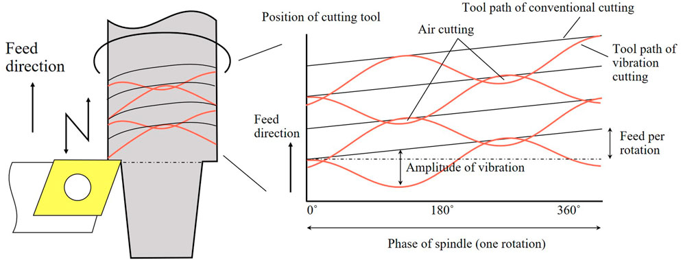
FIGURE 1. Concept of low-frequency vibration cutting.
The vibration is applied to a specified axis based on the following equation:
where I is the frequency ratio of the low-frequency vibration [-] with respect to the spindle speed S (min−1), and K is the amplitude ratio of the low-frequency vibration [-] with respect to the feed rate F (mm/rev). To break up chips, it is necessary to set the frequency and amplitude ratios such that the tool paths through the area that has already been cut, and the uncut portion is generated. The cutting-edge position is obtained using the following equation:
The spindle and tool-edge positions are calculated based on the calculation formula. Depending on the frequency and amplitude ratios, the location and size of the uncut portion changes relative to the spindle phase. When the frequency ratio is set to I = 1.0, an uncut portion is not generated.
2.2 Experimental setup
In this study, a multi-turret CNC lathe with two spindles on the left and right sides, two turrets with Z-axis, X-axis, and Y-axis on the upper part, and one turret with X-axis, Z-axis, and Y-axis on the lower part. In the experiment, the lower turret and right-hand spindle were used for machining. The lower turret has three axes and can reach the right spindle, as shown in Figure 2A. As shown in Table 1, 304 stainless steel was used because it is prone to chip disposal problems. The diameter of the material was 39.4 mm. A carbide insert (DNMG150408N-SM, Tungaloy) with an R0.8 rhombic 55° nose was used as the conventional tool. The cutting speed was 90 m/min, feed rate was .2 mm/rev, and cutting depth was .2 mm. The arguments for low-frequency vibration cutting were I = .5 and K = 1.5. A jig was constructed, as shown in Figure 2A, and a Kistler 9,121 dynamometer was installed on the tool-mounting area. The dynamometer amplifier was a Kistler 5,019 system, the high-speed analog measurement unit was a NR-HA08 (KEYENCE) system, and the data logger used was a NR-500 (KEYENCE) system, as shown in Figure 2B. The surface roughness was measured using a SURFCOM 1500DX (Tokyo Seimitsu) system with a diamond stylus with a radius of 2 μm and tip angle of 60°. Roundness was measured using a RONDCOM 44 (Tokyo Seimitsu) system, which was equipped with a tungsten carbide stylus with a diameter of 1.6 mm as the measuring element.
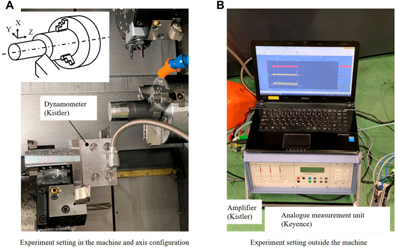
FIGURE 2. Configuration of experimental system.
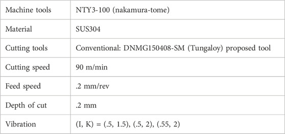
TABLE 1. Machining conditions.
For surface roughness, the maximum height Rz and arithmetical mean height Ra were calculated in accordance with the JIS B 0601 standard.
3 Issues associated with low-frequency vibration
3.1 Surface topography by low-frequency vibration cutting
Simulations were utilized to demonstrate the machined surface properties by plotting the tool trajectory based on the tool nose R, frequency ratio, and amplitude ratio (Miyake et al., 2020). The tool path can be calculated as follows:
From Eqs 3, 2 can be expressed using θ as follows:
Figure 3 is a color map with respect to the height of the machined surface when the parameters I and K were .5 and 1.5, respectively. The axes indicated the feed position, phase, and surface height of the workpiece, respectively. This allowed visual confirmation of the cutting area, air cutting, and machined surface when the I and K values were varied. The simulation method was based on a Z-map. The division width of the workpiece surface was set to 5 μm and .9° in the axial and peripheral directions, respectively. The division width of the ridge representing the cutting-edge shape of the tool was calculated as 1 μm. From Figure 3, it is confirmed how the surface is finished with the vibration. As the phase of cutting-edge changes, the contact point between the workpiece and tool also changes. As shown in Figure 3C, the surface roughness deteriorated according to the combination of I and K.
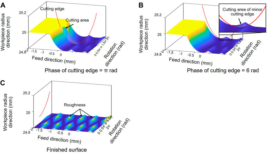
FIGURE 3. Prediction of surface roughness by low-frequency vibration (I = .5 and K = 1).
Based on the simulation results shown in Figure 3, when the parameters of I and K were .5 and 1.5, respectively, the surface roughness in low-frequency vibration cutting was 210.5% higher in Ra and 213.2% higher in Rz compared with that in W/O vibration.
Subsequently, the surface roughness and roundness were evaluated using the experimental system described in Section 2.2. The surface roughness varied depending on the phase, as shown in Figure 4; Table 2. In Figure 4, the horizontal and vertical axes denote the phase of the workpiece and surface roughness, respectively. The surface roughness during low-frequency vibration cutting was higher by up to 334.4% for Ra and up to 192.9% for Rz compared with that during W/O vibration.
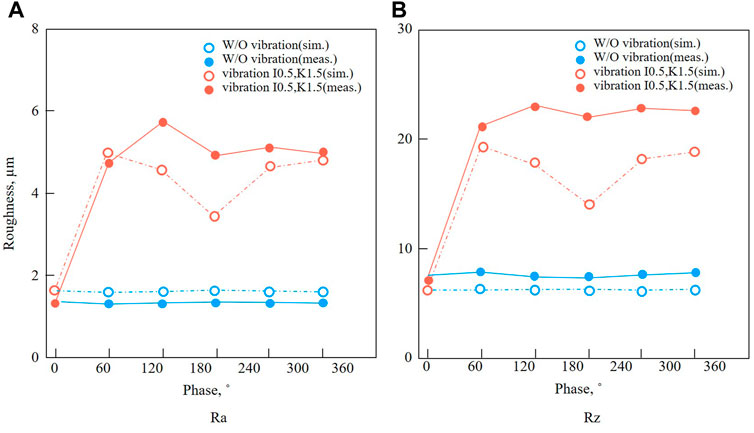
FIGURE 4. Measured surface roughness.
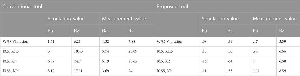
TABLE 2. Summary of surface roughness results.
As shown in Table 3, the average and maximum roundness during low-frequency vibration cutting was 146.4% and 575.8% higher, respectively, than that during W/O vibration. In terms of shape, a trend toward an elliptical shape was observed, which is similar to the simulation results. Based on the results for the cutting forces in Table 4, when compared with W/O vibration, the cutting force of low-frequency vibration cutting was higher by 50.8% for the principal force, 68% for the thrust force, and 40.8% for the feed force in terms of the maximum values. In terms of the average values, the values of the three component forces in low-frequency vibration cutting were lower than those in W/O vibration.
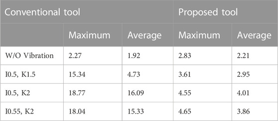
TABLE 3. Summary of roundness results.

TABLE 4. Summary of cutting force results.
3.2 Challenges of low-frequency vibration cutting
The surface roughness of low-frequency vibration cutting resulted in an Ra value that was 334.4% higher than that of W/O vibration. The periodic change in the tool path in low-frequency vibration cutting changed the height of the convexity formed on the finished surface and influenced the surface roughness.
Figure 5 shows the relationship between tool path variation and surface roughness at I = .5 and K = 1.5. In Figure 5, Z represents the axial position. The orange and blue lines represent the toolpath and surface roughness at each phase, respectively. As shown in Figure 5, the peak of the surface roughness was observed in the phase where the cutting-edge path distance was the maximum, which corresponded to twice the command feed rate. This was the case when K ≤ 2. The range in which K > 2 was considered difficult to use in practical applications due to the effect of vibration on the machine. The necessity for optimizing the amplitude according to the characteristics of the work material was discussed in a previous study (Paulsen et al., 2020). A practical range was reported in terms of chip breakup and its effect on the surface roughness (Miyake et al., 2020).
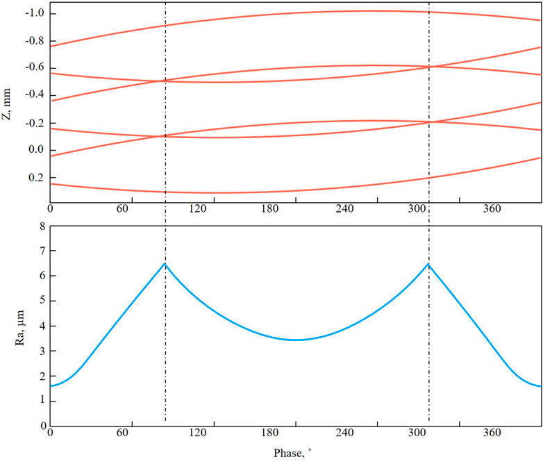
FIGURE 5. Path of the cutting edge and surface roughness in phase.
Additionally, even if arguments such as I (frequency ratio) and K (amplitude ratio) are adjusted, the spacing between the cutting-edge paths does not change at points where the gap between the cutting-edge paths is the widest. Therefore, this issue cannot be resolved by adjusting the arguments. In W/O vibration, the surface roughness can be improved by adjusting the feed rate. As reported, the feed rate increases or decreases to produce a machining path that breaks up chips (Smith et al., 2010). For low-frequency vibration cutting, the maximum feed rate is obtained as follows:
Here, Fmax is the maximum feed rate (mm/rev) during low-frequency vibration cutting, and F is the commanded feed rate (mm/rev). I is the frequency ratio of the low-frequency vibration [-], and K is the amplitude ratio of the low-frequency vibration [-]. Therefore, there is a periodic variation between the commanded and maximum feed rates. Adjusting the feed rate based on the maximum feed rate may result in inappropriate tool cutting conditions or a significant increase in the machining time. Hence, it is more difficult to adjust the feed rate in low-frequency cutting than in W/O vibration.
The roundness at the average and maximum values in low-frequency cutting is larger than that in W/O vibration. This is because, in W/O vibration, the tool path is periodically changed, and the workpiece does not constantly have contact with the cutting edge during cutting, which reduces the roundness.
4 Design of cutting tool for low-frequency vibration
4.1 Proposal of tool geometry
This study proposes a tool shape that improves the surface roughness and roundness to address the shortcomings of low-frequency vibration cutting. The surface roughness deteriorates due to the relationship between the tool geometry and path with the conventional tool, as shown in Figure 3. There are two strategies to improve this. The first is to increase the nose radius of the cutting tool, and the second is to use a straight edge at the tip of the cutting tool, as shown in Figure 6. Preliminary experiments revealed that a cutting tool with a large nose radius does not sufficiently improve surface roughness. However, when a cutting tool has a straight edge, such as a tool for hard skiving, the contact area between the workpiece and cutting tool increases, making chattering vibration more probable. Given that the chattering vibration exhibits a negative influence on the machined surface, the straight part should be maximally short. Therefore, a cutting tool with a large nose radius and straight edge, which is similar to a wiper cutting tool, was proposed. Commercially available wiper chips have straight sections that are either too short, such as .2 mm, or too long, such as over .45 mm. Furthermore, both R1 and R2 in commercial wiper tools have an average smaller R than the proposed tool. The proposed tool consists of a straight section L and two radius sections R1 and R2, as shown in Figure 6. As previously mentioned, a long straight section induces chattering vibration; therefore, it is necessary to accurately determine these parameters considering the low-frequency vibration cutting mechanism.
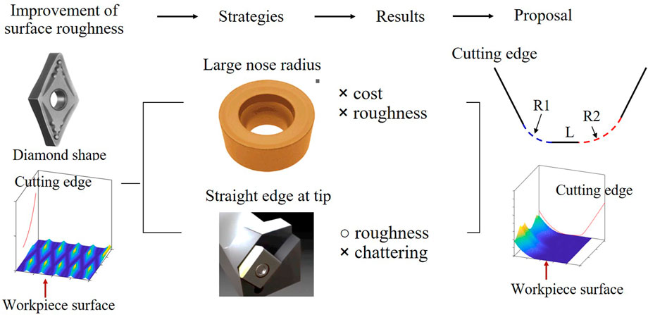
FIGURE 6. Design strategy of cutting tool for low-frequency vibration.
4.2 Optimization of tool shape
Figure 7 presents a schematic of the proposed cutting tool. As previously mentioned, the cutting tool had a straight section on the nose. To improve the roughness of the machined surface, the parameters L, R1, and R2, as shown in Figure 7, should be determined.
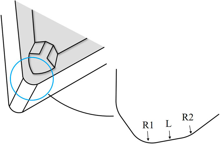
FIGURE 7. Parameters of proposed cutting tool for low-frequency vibration.
To determine the length L, it is necessary to obtain the feed amount during low-frequency vibration cutting. However, owing to the back cutting caused by minor cutting edge, as shown in Figure 3B, the finished surface could be re-cut. In general, the feed amount considering future cutting can be calculated as follows:
Nf and Nb refer the number of upcoming and previous cutting paths, respectively. The first part of the equation represents the minimum feed amount of the upcoming cutting, while the second part is the maximum feed amount of the previous cutting. Based on Eq. 6, the relationship between I, K, and the maximum feed amount can be obtained. In Figure 8A, the black lines represent the feed amount of the cutting tool, and the orange line represents the maximum feed, whose vertical axis is on the right side. The maximum feed occurs in the phase where two adjacent feed paths cross each other. The maximum feed is .4 mm when I and K are .5 and 1.5, respectively. Figure 8B presents the maximum feed for a larger range of I and K. It can be observed that the maximum feed amount varies with different combinations of I and K. In addition, by setting the threshold value of the maximum feed amount to 2F, an appropriate range of I and K can be determined, in which I is centered around .5 and K determines the range. Considering the periodicity in Eq. 6, the same results can be achieved for other values of I.
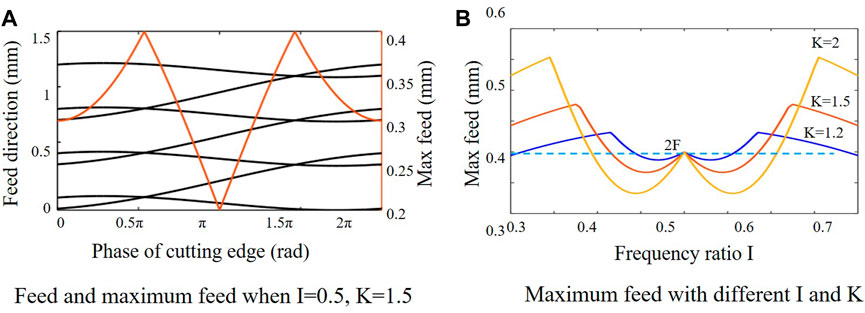
FIGURE 8. Maximum feed amount in low-frequency vibration.
Compared with W/O vibration, determining suitable parameters for I and K could make the feed smaller than 2F in low-frequency vibration cutting. Although there is an optimal combination of I and K for the minimum feed amount, a series of calculations is necessary. Moreover, for values of I other than .5, where the maximum feed is always 2F, the influence of the parameter K can be ignored. Therefore, in this study, the maximum feed in low-frequency vibration cutting was considered as 2F.
In the low-frequency vibration cutting process, the straight section of the tool edge influences the workpiece surface when its length is greater than 2F, and the theoretical surface roughness is 0. Conversely, when it is smaller than 2F, the surface roughness is greater because all feed marks remaining on the workpiece surface are influenced by the R sections before and after the straight section. The scallop height is approximately expressed by the following equation:
Therefore, the optimum value of the proposed tool shape can be obtained by first determining the machining conditions to an extent (feed rate), then optimizing the length of the straight section. However, if the length of the straight section exceeds a certain level, it may have a negative effect on cutting resistance. Therefore, their lengths are limited. The length of the proposed tool is set to .41 mm, which is twice as long as F = .2 mm/rev, and a finishing feed is used. Accordingly, the proposed tool is shown in Figure 9.
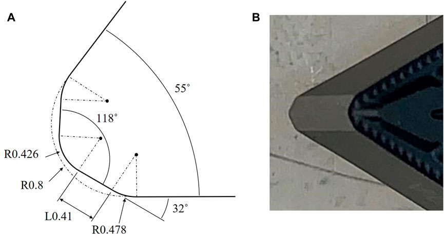
FIGURE 9. Proposed and manufactured cutting tool.
Figure 10 presents the surface roughness simulation of low-frequency vibration cutting for the conventional and proposed tools. In Figure 10, the horizontal and vertical axes represent the longitudinal position and phase of the workpiece, respectively. The conditions are identical to those shown in Figure 3. As observed, using the proposed tool, the surface roughness can be reduced from 5.00 µm to .15 µm in Ra and from 19.45 µm to .56 µm in Rz. Thus, the proposed tool is effective for vibration-assisted cutting.
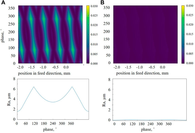
FIGURE 10. Surface roughness simulation of low-frequency vibration cutting (I = .5 and K = 1.5).
5 Results
Based on the analytical results, experiments were conducted to clarify the surface roughness, roundness, and cutting force of low-frequency vibration cutting by installing the proposed tool in a multi-turret CNC lathe, as shown in Figure 2. The experimental configuration is listed in Table 1. The cutting speed was 90 m/min, feed rate was .2 mm/rev, and cutting depth was .2 mm. The parameters for low-frequency vibration cutting were (I, K) = (.5 1.5), (.5, 2), and (.55, 2). The combinations of I and K were changed, and their influences were investigated.
5.1 Cutting chips
Figure 11 presents a comparison of the chips between the two tool types. Four patterns based on the cutting method and cutting tool were used in the experiment. With both the conventional and proposed tools, the chips were broken up when vibration was added, in contrast to the long pieces in W/O vibration. Based on the results, vibration-assisted machining with I = .5 and K = 1.5 can reliably break up chips. In addition, the curl radius of the cutting chips using the proposed tool was smaller than that of the conventional tool. This was owing to the contact length between the tool and chip. More focus should be directed toward the difference in chip speeds between the front and back sides.
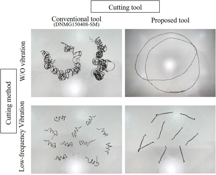
FIGURE 11. Cutting chips (I = .5 and K = 1.5 for vibration-assisted cutting).
5.2 Surface roughness
Figure 12 presents the results of the surface roughness obtained using the proposed tool (I = .5 and K = 1.5). Table 2 presents a summary of the surface roughness that changed the vibration conditions. The experimental results revealed that the surface roughness when using the proposed tool significantly improved from 5.74 µm to .94 µm in Ra and from 23.09 µm to 6.66 µm in Rz.
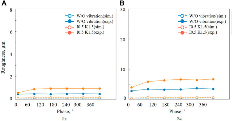
FIGURE 12. Results of surface roughness measurement for the proposed tool.
From Table 2, several points have to be considered. First, the error between the simulation and measurement was small for the conventional tool. This was true for cases with and without vibration. However, when using the proposed tool, the error between the simulation and measurement was not negligible; that is, experimental results had poorer performance than the simulation results. This may be because cutting with the proposed tool was slightly less stable due to the contact length. However, the surface roughness of the proposed tool was superior than that of conventional cutting (using conventional tools W/O vibration) and vibration-assisted cutting. When the parameters of vibrations I and K were changed, the difference was not significant. The influence of I and K should be further investigated; however, when the parameter K was large, the surface properties were degraded. This indicates that having a large amplitude influences cutting stability. In addition, the limitation of the relationship between I and K should be considered to break the chips. When the parameter I was set to .55, the vibration phase changed at each rotation. Moreover, the surface roughness was expected to improve due to the dispersion effect of the tool path (Miyake et al., 2018). In particular, this effect was confirmed only in the simulation results for the conventional tool. Thus, this area requires further investigation.
5.3 Roundness
Figure 13 presents the roundness of the workpiece after turning. Roundness is one of the most critical evaluations of the machining results. In the case of normal turning under the abovementioned conditions, the average roundness was 1.92 µm and the maximum roundness was 2.27 µm, as shown in Figure 13 and Table 3. As shown in Figures 13B, C, vibration-assisted machining did not produce roundness of the same quality as that of the normal turning process, which is a common problem associated with vibration-assisted machining.
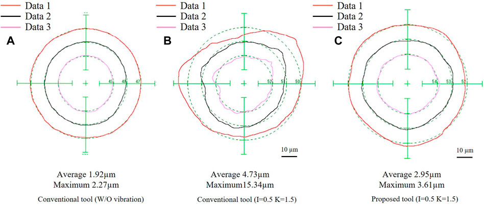
FIGURE 13. Roundness measurement results for the proposed tool.
However, when the proposed tool was used, the average roundness improved, as shown from Figures 13B, C. The average roundness decreased from 4.73 µm to 2.95 µm, and the maximum roundness decreased from 15.34 µm to 3.61 µm.
5.4 Cutting force
The results for the cutting forces are presented in Figure 14 and Table 4. The data were calculated from 10 vibration cycles. The coordinate system of the machine tool is illustrated in Figure 2. In the case of low-frequency vibration cutting with the proposed tool, the average value of the cutting force was almost the same as that of W/O vibration. Regarding the maximum cutting force, the thrust, principal, and feed force values of low-frequency vibration cutting were 46.2%, 58.1%, and 34.4% higher, respectively, than those of W/O vibration.
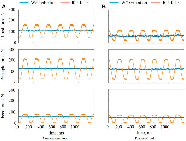
FIGURE 14. Cutting force results (I = .5 and K = 1.5).
The average and maximum values of the cutting forces using the proposed tool were found to be lower than those of the conventional tool. The maximum and average thrust force, where the largest difference was observed, when using the proposed tool were 29.7% and 35.7% lower, respectively, than when using the conventional tool.
5.5 Tool wear
The effect of low-frequency vibration cutting on the tool life was investigated using both the conventional and proposed tools. In the experiment, actual machining was performed using a multi-turret CNC lathe (NTY3-100), and tool wear was observed using an electron microscope (Keyence, VK-X210). The conditions were V = 90 m/min, F = .2 mm/rev, and t = .4 mm. The material was SUS304. A non-coated insert (Tungaloy, DNMA150408 TH10) was used as the conventional tool. Figure 15 shows the cutting distance and flank wear width on the horizontal and vertical axis, respectively. From Figure 15, the proposed tool with low-frequency vibration cutting and conventional tool with W/O vibration exhibited almost the same service lives.
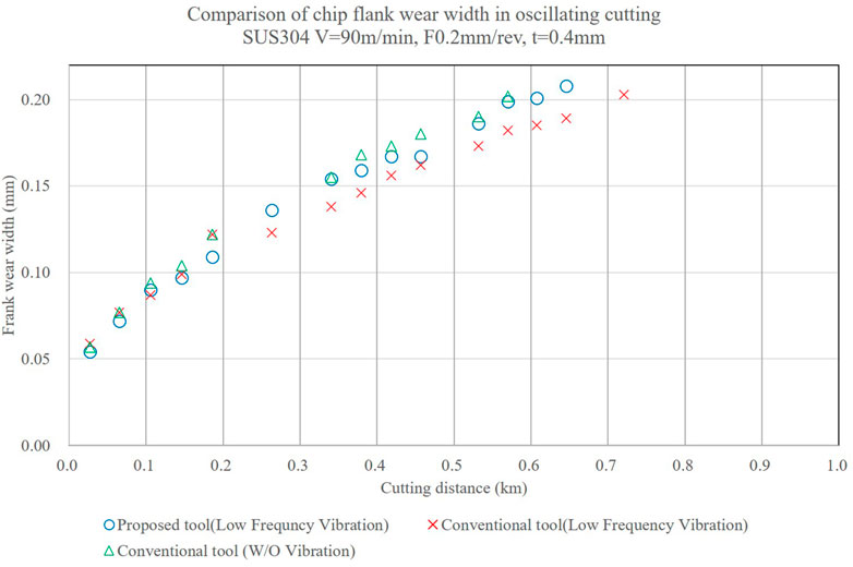
FIGURE 15. Comparison of chip flank wear width in oscillating cutting.
6 Discussions
The experimental results revealed that the deterioration of the surface roughness and roundness caused by low-frequency vibration cutting can be reduced by designing an appropriate tool shape. The surface roughness of the proposed tool was significantly lower than that of the conventional tool because the straight part of the tool filled the gap and reduced the convexity to the point at which the gap between the cutting-edge paths increased in size. There were several differences between the values measured in the simulation and those obtained from actual machining using the proposed tool. Depending on the cutting conditions, the chip form become tear type, and the machine surface get clouded. This might have influenced the gap in the simulation and actual machining results. This situation was likely to occur because of the reduced peripheral speed and material used (stainless steel). The roundness of the proposed tool was improved compared with that of the conventional tool. This result is attributed to the fact that the effect of the periodic machining path was reduced by the straight section, and the cutting edge had contacts with the workpiece more consistently.
Regarding the cutting force using the conventional tool, the average value was not significantly different from that of the W/O vibration, whereas the maximum value of each cutting force was higher than those of W/O vibration. This trend can be attributed to the presence of a peak in the cutting force due to periodic vibration; however, the creation of the uncut portion resulted in a low average value. In terms of the proposed tool, the maximum values of cutting force were higher than those of W/O vibration. With respect to maximum values of thrust and principal forces, the gaps were larger than those of the conventional tools. The straight section extended the time for which the tool was in contact with the workpiece. Then, periodic trajectory changes led to peaks in the cutting force. These factors were considered to influence the gaps between the cutting methods. Based on a comparison of the cutting forces of the proposed and conventional tools, the average value of the thrust force using the proposed tool were significantly smaller. The side cutting edge angle of the proposed tool is smaller than that of the conventional tool. Thrust force decreases as the side cutting edge angle decreases in the case that side cutting edge corner is in contact with the workpiece (Lee et al., 2007). The side cutting edge angle of the proposed tool is smaller than that of the conventional tool. It's possible that the thrust force of the proposal tool was smaller than that of the conventional tool because of its effect. Variations in the cutting force influenced the tool life. The tool-life measurement results revealed that there was no significant difference between the proposed tool with low-frequency vibration cutting and the conventional tool with W/O vibration. The relationship between these variations in the cutting load and tool life will be the focus of future research. The findings of this study demonstrate that the surface roughness and roundness in low-frequency vibration cutting can be improved using the proposed tool shape.
7 Conclusion
This paper proposes a cutting tool designed for low-frequency vibration cutting. In this study, simulations and experiments were conducted to clarify the effects on surface roughness and roundness.
1. During low-frequency vibration cutting with the proposed tool, the surface roughness was reduced, from 5.74 µm to .94 µm in Ra and from 23.09 µm to 6.66 µm in Rz, compared with that of the conventional tool.
2. The average roundness with the proposed tool on low-frequency vibration improved, from 4.73 µm to 2.95 µm, when compared with that of the conventional tool. The maximum value was reduced from 15.34 µm to 3.61 µm using the proposed tool. Moreover, the roundness of the low-frequency vibration should be investigated further.
3. Regarding the cutting force, the average and maximum values of the proposed tool were lower than those of the conventional tool. The maximum and average thrust force of the proposed tool, where the largest difference was observed, was 29.7% and 35.7% lower, respectively, than those of the conventional tool.
Data availability statement
The original contributions presented in the study are included in the article/Supplementary Material, further inquiries can be directed to the corresponding author.
Author contributions
SN: writing papers, compiling previous research, and analyzing experimental data. KN: support for processing experiments and data analysis. KO: support tool design, set conditions for machining experiments. YN: conduct machining experiments, tool design. ZR: development of simulations and theoretical formulas. TK: support for data analysis and discussion. NS: review and additions to the paper, and the structure of the paper.
Acknowledgments
The authors would like to acknowledge TOKO Co., Ltd., for the support provided during this research.
Conflict of interest
Authors SN, KN, KO, and YN were employed by Nakamura-tome precision industry Co., Ltd.
The remaining authors declare that the research was conducted in the absence of any commercial or financial relationships that could be construed as a potential conflict of interest.
Publisher’s note
All claims expressed in this article are solely those of the authors and do not necessarily represent those of their affiliated organizations, or those of the publisher, the editors and the reviewers. Any product that may be evaluated in this article, or claim that may be made by its manufacturer, is not guaranteed or endorsed by the publisher.
References
Berglind, L., and Ziegert, J. (2015). Modulated tool path (MTP). Machining for threading applications. 43rd Proc North Am. Manuf Res 1, 546–555. doi:10.1016/j.promfg.2015.09.029
Bleicher, F., Reiter, M., and Brier, J. (2019). Increase of chip removal rate in single-lip deep hole drilling at small diameters by low-frequency vibration support. Manuf. Tech. 68, 93–96. doi:10.1016/j.cirp.2019.04.028
Copenhaver, R., Rubeo, M. A., Guzorek, S., Landge, S., Smith, K. S., Ziegert, J., et al. (2017). A fundamental investigation of modulated tool path turning mechanics. Procedia Manuf. 10, 159–170. doi:10.1016/j.promfg.2017.07.043
Guo, Y., Stalbaum, T., Mann, J., Yeung, H., and Chandrasekar, S. (2013). Modulation-assisted high speed machining of compacted graphite iron (CGI). J. Manuf. Process 15, 426–431. doi:10.1016/j.jmapro.2013.06.001
Hirota, H., and Shinozaki, N. (1970). Chip breaking by rolling tool. J. Jpn. Soc. Precis. Eng. 36/2, 135–140. doi:10.2493/jjspe1933.36.135
Hussein, R., Sadek, A., Elbestawi, M. A., and Attia, M. H. (2019). An investigation into tool wear and hole quality during low-frequency vibration-assisted drilling of CFRP/Ti6Al4V stack. J. Manuf. Mater Process 3, 63. doi:10.3390/jmmp303006310.3390/jmmp3030063
Hussein, R., Sadek, A., Elbestawi, M. A., and Attia, M. H. (2020). Effect of process parameters on chip formation during vibration-assisted drilling of Ti6Al4V. Int. J. Adv. Manuf. Technol. 106, 1105–1119. doi:10.1007/s00170-019-04627-9
Lee, H., Toride, A., Yamada, A., and Araki, S. (2007). Study on the generation of micro shafts by turning operation. J. Jpn. Soc. Abras. Technol. 51 (11), 657–661. doi:10.11420/jsat.51.657 No.
Mann, J. B., Guo, Y., Saldana, C., Compton, W. D., and Chandrasekar, S. (2011). Enhancing material removal processes using modulation-assisted machining. Tribol. Int. 44, 1225–1235. doi:10.1016/j.triboint.2011.05.023
Maroju, N. K., Vamsi, K. P., and Xiaoliang, J. (2017). Investigations on feasibility of low-frequency vibration-assisted turning. Int. J. Adv. Manuf. Technol. 91, 3775–3788. doi:10.1007/s00170-017-0034-6
Miyake, A., Kitakaze, A., Katoh, S., Muramatsu, M., Noguchi, K., Sannomiya, K., et al. (2018). Chip control in turning with synchronization of spindle rotation and feed motion vibration. Prec Eng. 53, 38–45. doi:10.1016/j.precisioneng.2018.02.012
Miyake, A., Kitakaze, A., Katoh, S., Muramatsu, M., Noguchi, K., Sannomiya, K., et al. Effect of low frequency vibration applied to feed direction on turning process (2016). 2016 International Symposium on Flexible Automation (ISFA) doi:10.1109/isfa.2016.7790188Cleveland, OH, USA
Miyake, A., Kitakaze, A., Sakurai, S., Muramatsu, M., Noguchi, K., Sannomiya, K., et al. (2020). Influence on surface characteristics generated in low frequency vibration cutting. JSME 86/892, 20-00323–00323. doi:10.1299/transjsme.20-00323
Moriwaki, T., and Shamoto, E. (1995). Ultrasonic elliptical vibration cutting. CIRP Ann. 44/1, 31–34. doi:10.1016/s0007-8506(07)62269-0
Okamura, K., Sasahara, H., Segawa, T., and Tsutsumi, M. (2006). Low-frequency vibration drilling of Titanium alloy. JSME Int. J. Ser. C 49/1, 76–82. doi:10.1299/jsmec.49.76
Paulsen, T., Guba, N., Sölter, J., and Karpuschewski, B. (2020). Influence of the workpiece material on the cutting performance in low frequency vibration assisted drilling. CIRP J. Manuf. Sci. Technol. 31, 140–152. doi:10.1016/j.cirpj.2020.10.003
Pecata, O., and Brinksmeier, E. (2014). Tool wear analyses in low frequency vibration assisted drilling of CFRP/Ti6Al4V stack material. Procedia CIRP 14, 142–147. doi:10.1016/j.procir.2014.03.050
Seeholzer, L., Voss, R., Marchetti, L., and Wegener, K. (2019). Experimental study: Comparison of conventional and low-frequency vibration-assisted drilling (LF-VAD) of CFRP/aluminium stacks. Int. J. Adv. Manuf. Technol. 104, 433–449. doi:10.1007/s00170-019-03837-5
Smith, S., McFarland, J., Assaid, T., Tursky, D., Barkman, W., and Babelay, E. (2010). Surface characteristics generated in CNC chip breaking tool paths. CIRP Ann. 59, 137–140. doi:10.1016/j.cirp.2010.03.060
Smith, S., Woody, B., Barkman, W., and Tursky, D. (2009). Temperature control and machine dynamics in chip breaking using CNC toolpaths. CIRP Ann. 58, 97–100. doi:10.1016/j.cirp.2009.03.061
Woody, B. A., Smith, K. S., Adams, D. J., and Barkman, W. E. (2008). Assessment of the process parameters and their effect on the chip length when using CNC toolpaths to provide chip breaking in turning operations. Trans. NAMRI 36, 1–8. doi:10.1115/msec_icmp2008-72468
Yang, H., Ding, W., Chen, Y., Laporte, S., Xu, J., and Fu, Y. (2019). Drilling force model for forced low frequency vibration assisted drilling of Ti-6Al-4V titanium alloy. Int. J. Mach. Tool. Manu 146, 103438. doi:10.1016/j.ijmachtools.2019.103438
Keywords: low frequency vibration, surface roughness, roundness, surface property, tool design, lathe, turning
Citation: Nakamura S, Nakanishi K, Ohara K, Nakamura Y, Ren Z, Kizaki T and Sugita N (2023) Tool design for low-frequency vibration cutting on surface property. Front. Manuf. Technol. 2:1079127. doi: 10.3389/fmtec.2022.1079127
Received: 25 October 2022; Accepted: 28 December 2022;
Published: 13 January 2023.
Edited by:
Yasuhiro Kakinuma, Keio University, JapanCopyright © 2023 Nakamura, Nakanishi, Ohara, Nakamura, Ren, Kizaki and Sugita. This is an open-access article distributed under the terms of the Creative Commons Attribution License (CC BY). The use, distribution or reproduction in other forums is permitted, provided the original author(s) and the copyright owner(s) are credited and that the original publication in this journal is cited, in accordance with accepted academic practice. No use, distribution or reproduction is permitted which does not comply with these terms.
*Correspondence: Shogo Nakamura, c2hvZ28tbmFrYW11cmFAbmFrYW11cmEtdG9tZS5jby5qcA==