
94% of researchers rate our articles as excellent or good
Learn more about the work of our research integrity team to safeguard the quality of each article we publish.
Find out more
ORIGINAL RESEARCH article
Front. Manuf. Technol., 20 October 2022
Sec. Material Forming and Removal
Volume 2 - 2022 | https://doi.org/10.3389/fmtec.2022.1012343
This article is part of the Research TopicRolling Bearing Optimization through Innovative Manufacturing ProcessesView all 4 articles
The application of microdimple-textured surfaces for rolling bearings is not very common but can be beneficial for various usage scenarios. In contrast to the applications for plain bearings or cylinder running surfaces, however, surface patterns for rolling bearings only offer advantages under certain conditions. For example, for use with start-stop cycles, in mixed lubrication conditions, or under sliding conditions in a bearing as well as on a roller—bearing flange contact, friction can be reduced with the targeted use of microtextures. The geometry of the microtextures must be chosen so that individual dimples fit in the contact area between the ball or roll and the bearing surface in order to act as a reservoir for the lubricant. First applications for microtextured angular contact ball bearings under oscillating movement conditions proved friction reducing effects under reciprocating motion. In this case the microtextures served as lubricant reservoirs. The idea is transferred to the sliding contact for tapered roller bearings; it is investigated whether the measured reductions in friction are due to the microtextures serving as lubricant reservoirs or whether there is even a positive hydrodynamic effect caused by the microtextures. By means of a calculation approach as well as some exemplary test rig measurements, the behavior for microtextured tapered roller bearings is investigated.
The friction-reducing effect of microdimple-textured surfaces in lubricated friction contacts has been shown in previous studies. Applications can be found in surface microtexturing of cylinder liner contacts (Willis, 1986; Jeng, 1996). In addition, the contact conditions for Micro-Electro-Mechanical Systems can be improved by microtexturing (Komvopoulos, 2003). Gropper et al. (2016) presented applications of surface texturing in hydrodynamic lubrication like parallel thrust pad bearings or journal bearings and numerial models to evaluate textures prior manufacturing. Investigations using a disc-on-disc tribometer proved that microtextures can drastically reduce the frictional properties and achieve hydrodynamic lubrication at lower sliding speeds (Kästner, 2013; Ulmer et al., 2015). In addition, simulation studies have shown that patterns across the raceway provide the highest friction reduction (Kästner, 2013).
In pin-on-disc experiments Taee et al. (2017) showed that laser microtexturing can improve the running-in behaviour. In addition, wear can be reduced and the coefficient of friction can be reduced by 12%–23%. Furthermore, Pakuła et al. (2019) have shown that laser microtexturing with nano riffles can reduce wear under tribological stress for sintered materials. Henry. (2013) were able to demonstrate that the lubrication pocket geometry has a great influence on the effectiveness for structured thrust bearings. Tremmel et al. (2019) investigated laser textured mechanical bucket tappets for the cam-tapper contact. For a combined rolling-sliding EHL contact, a simulation model was set up to achieve optimized microtextures.
Surface texturing can directly influence the friction and wear behavior of contact surfaces in many ways. Firstly, microtextures can improve the load carrying capacity of the lubricant film through an enhanced hydrodynamic effect caused by the lubricant stored in the microtextures (Tauviqirrahman et al., 2014). Secondly, the lubricants stored in the microtextures can improve the lubrication condition in case of insufficient lubrication (Li et al., 2014). Thirdly, wear particles can be captured by the microstructures, which reduces abrasive wear between the contact surfaces (Sagbas and Durakbasa, 2013). An additional effect can be an enhancement of beneficial tribofilm growth, as reported by Hsu et al. (2017) for textured cylindrical roller bearings Hsu et al., 2021).
Vrbka et al. (2010) investigated rolling contact fatigue (RCF) of surface textured non-conformal rolling/sliding contacts under mixed lubrication conditions. They could prove that RCF is influenced on the size and density of the micro-dents in contact.
Microdimple textures can be manufactured via laser machining (Wakuda et al., 2003; Kästner, 2013). According to Etsion. (2005), laser surface texturing is a promising process to achieve dimples with high accuracy. Laser texturing was previously applied on implant surfaces and journal bearing surfaces (Brizmer and Kligerman, 2012; Braun et al., 2014; Ghosh and Abanteriba, 2016). For micro-texturing there are also alternatives like focused ion beam (FIB) etching or electron beam etching, presented by Gachot et al. (2017). In the field of plain bearings, there are studies on laser structuring of surfaces in order to facilitate hydrodynamic lubricant film formation, especially during start-up. Braun et al. (2014) could achieve a reduction of friction by 80% under certain operating conditions for a surface provided with microtextures.
The cutting processes for microtexturing include micro planing, turning, milling, and grinding. The approach of creating dimples within a machining process with a single tooth chamfer after honing offers high geometric flexibility and low effort, featuring individual microdimple lengths of a few hundred microns, and widths and depths starting from a few microns. The aim is to provide a lubricant reservoir inside the tribological contact at standstill and improve fluid film build-up at low relative speeds. The application of a microtextured surface on angular contact ball bearings by milling with a single tooth chamfer was presented by Pape et al. (2017).
We intend to apply this methodology to tapered roller bearings; tapered roller bearings are preferably used in the drive train or in the wheel bearing arrangement of commercial vehicles. In the German automotive industry, more than 10 million tapered roller bearings are used annually (Daimler, 2013). As roller bearings, they can support high loads due to the linear contact in the rolling surfaces. Due to their contact angle, they can support radial, axial, and combined loads. In addition, they can support high tilting moments in small installation spaces without the need for additional bearings for support.
The bearing flange is the critical tribological contact in tapered roller bearings. The external bearing load, both its radial and its axial components, is transmitted for the most part as a normal force between the rollers and raceways, where there is almost pure rolling motion with negligible sliding components. Even without external axial load, there are internal axial forces between roller side and flange which are transmitted via a contact area that is stretched out in the circumferential direction. Although this contact has the advantage that the rollers are effectively guided and prevented from skewing, the transmission of force between rollers and flange takes place with kinematically induced slip; sliding movements in circumferential direction and spin overlap.
The critical operating conditions for tapered roller bearings involve low speeds and high loads (Wang, 2015). In these cases, the contact point between the roller and flange is operating under mixed lubrication conditions and contributes most of the frictional torque (Wang, 2015). In the drive train of a commercial vehicle, for example, these conditions occur during starting and stopping. Improved tribological properties for this contact can thus have a large impact on the efficiency of commercial vehicles.
For this purpose, we first review a setting in which microtextures were successfully applied, namely for angular contact ball bearings, with the aim of applying a similar microtexturing process to the flange surface of tapered roller bearings.
In a preliminary study, angular contact ball bearings were operated under pivoting motion. These bearings were equipped with a microtextured surface. By applying a microtexturing process as described by Kästner. (2013), microtextures can also be produced on hardened materials using a one-tooth chamfer. Figure 1 depicts an angular contact ball bearing with a microtextured surface. It is possible to structure the whole raceway surface, with the aim of allowing the dimples to trap lubricant into the contact between the ball and raceway.
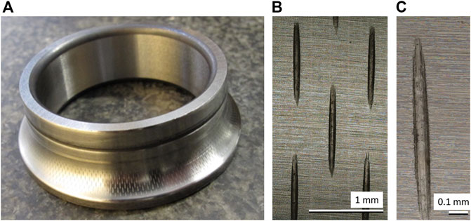
FIGURE 1. Textured angular contact ball bearing (type 7208): (A) overview (B) array of dimples (C) single dimple.
In order to be able to experiment on bearings operating at small pivoting angles, a test rig was designed and built (Pape et al., 2016). This test rig can test two angular contact ball bearings in back-to-back arrangement. A servomotor is used to operate the bearings in a pivoting motion and a disc spring assembly applies a purely axial load to the bearing. A torsional strain gauge and a rotary encoder were installed to enable the measurement of friction in combination with angular resolution, i.e., with the ability to correspond a friction measurement with an instantaneous angular position of the pivoting motion. This makes it possible to investigate the friction properties at the reversal points of the pivoting motion; at the reversal points, the balls’ velocity is zero and the risk of increased friction and wear due to mixed lubrication is more severe. To investigate this, the bearing surfaces at the reversal points were examined by laser scanning microscopy (Keyence VK-X200, Keyence Corporation, Osaka, Japan) in order to be able to draw conclusions about the surface damage in comparison to bearings from mass production.
Modified angular contact ball bearings of type 7208 were tested in pivoting motion with a reduced number of 7 (out of 14 originally) balls. Due to the reduced number of balls, the pivoting motion does not lead to an overlap of the traveled paths of separate balls on the bearing raceway. The average roughnesses of the inner ring and rolling elements was measured using laser scanning microscopy (Keyence VK-X200, Keyence Corporation, Osaka, Japan), yielding values of Ra = 0.04 µm for the rolling elements and Ra = 0.2 µm for the inner ring, respectively. A pivoting angle of 48° (+-24°) was used with a frequency of 5 Hz for 1.2 million pivot cycles. The axial load applied on the bearings via the disc spring assembly was 2.4 kN. The resulting Hertzian pressure for the ball-inner ring contact was 1.5 GPa with contact semi-axis dimensions of a = 1.2 mm and b = 0.2 mm. The tests were performed using grease (Klüber Topas L152, Klüber Lubrication Munich SE & Co. KG, Germany) for lubrication, filled to 30% of the bearing’s free volume.
For the microtextured bearings the frictional torque could be reduced over the course of the pivoting angle in comparison to untextured, standard bearings. This can be seen in Figure 2, which shows measured frictional torque over the pivoting angle for a standard bearing in comparison to a microtextured bearing (the torque measurement was performed at 0.2 Hz to prevent the rotational gauge bar from damage). The surface texturing by microdimples has a major influence on the achieved frictional properties of the bearings. The microtexture allowed the reduction of the frictional torque by half.
Furthermore, it could be shown that, in long-term tests at a higher pivoting frequency of 5 Hz and over 1.2 million cycles, the wear on the running tracks was reduced by the microtexture Figure 3A). shows an optical image of a bearing raceway for a microtextured bearing surface before an experiment. The length of a single dimple is approximately 750 μm, the width is approximately 30 μm, and the depth approximately 10 µm. At the reversal point of the balls, wear marks can be found. A reversal point for a microtextured bearing after test is shown in Figure 3B). For comparison, a reversal point for a standard bearing after test is depicted in Figure 3C) showing increased wear.
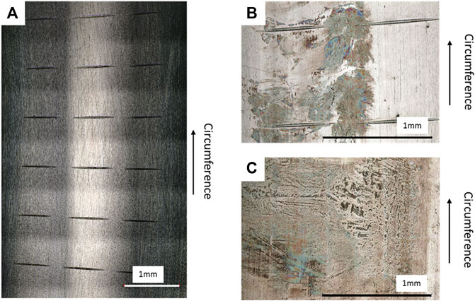
FIGURE 3. Optical images on bearing raceways: (A) textured bearing before test (B) textured bearing surface on reversal point after test (C) standard bearing surface on reversal point after test.
Thus it was shown that the microtextured bearings improved both measured friction and wear characteristics. Especially in this field, a friction reduction results in significant energy savings. The effect could be also proven in further studies performed with microtextured constant velocity joints (Pape et al., 2022). In this study a reduction of measured power losses on structured constant velocity joints of 20% were achieved compared to serial constant velocity joints.
As a next step the concept is to be extended to tapered roller bearings. Here, the initial aim is to investigate the physical phenomena that can lead to the reduction in friction that was observed for the angular contact ball bearing. Following this, it is investigated how this might be applied to reduce the friction between the roller end and the bearing flange. A calculation approach to investigate the contact conditions, simulations of theoretical film thickness, and measurement results are presented.
Based on the experience with beneficial microtextured surfaces on angular contact ball bearings, we attempt to transfer these results to the application of tapered roller bearings. The aim is to optimize the flange contact in tapered roller bearings by microtexturing (applying also a one-tooth chamfer) and to clarify if such dimples act as lubricant reservoirs at low speeds and investigate their hydrodynamic effects.
We first consider an overview of the contact conditions for the tapered roller bearing flange contact as well as a preliminary calculation. Part of the functionality of the roller-flange contact is to counteract internal axial forces that result from the contact angles of the raceways relative to the applied external load. Additionally, the rollers are prevented from skewing due to the normal force resulting from the roller-flange contact. A CAD model of a bearing segment is shown in Figure 4A), with the inner ring raceway and flange shown in Figure 4B). As is shown in Figure 5, the contact conditions cause overlapping sliding and spinning slip.
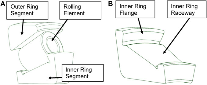
FIGURE 4. Tapered roller bearing (A) CAD Model of 31312 bearing segment, (B) view of the bearing inner ring segment with flange and raceway.
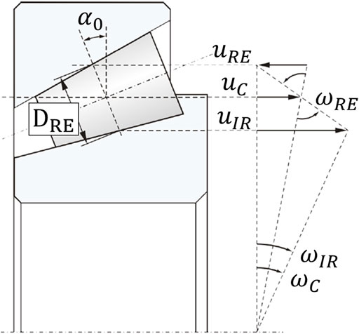
FIGURE 5. Contact conditions: schematic of the roller-flange contact kinematics (Wang, 2015).
The true shape of the roller-flange contact area is also an area of active research (Wheeler, 2018; Kelley et al., 2022). The shape of the contact area after deformation depends to a large degree on the macrogeometry of the contacting bodies, which depends on the exact bearing model (Kieckbusch, 2017). The contact partners of a bearing of type 31312-A were measured and the macrogeometry was determined to be similar to a torus on cone contact. A priori it is unclear whether the contact can be modelled as a conventional elliptic contact, necessitating finite element analysis.
To this end a finite element model of the bearing was set up using the measured geometry of a tapered roller bearing of type 31312-A. Relevant parameters are shown in Table 1; the boundary conditions and contact area are shown in Figure 6. The results of the finite element analysis show that this particular macrogeometry at this load results in a nearly elliptical contact with only a very slight curve, which may be adequately approximated using an elliptical contact. The reason for the nearly straight shape is the counteracting curvature lines of the two contacting bodies. On the one hand, the conical flange would lead to a downwards curve of the pressure and deformation in Figure 6, but on the other hand, the toroidal roller end would cause an upward curve. These effects counteract in this case to cause a near straight, elliptical contact geometry.

FIGURE 6. Finite element analysis (A) Flange contact pressure (B) deformation on flange showing a near-elliptical but slightly curved contact shape.
To evaluate the effect of the dimples on film thickness and fluid friction, an EHL calculation model, where the primary unknowns that are calculated are the fluid film pressure and film thickness, is required. This involves solving the elasticity equations for the deformation of the geometry due to the film pressure in conjunction with the calculation of the film pressure from the deformed geometry, operating conditions (temperature, normal load, surface speeds), and rheological models of the fluid.
Due to its superior convergence properties, a fully-coupled EHL solver following Habchi was implemented. This solution method simultaneously solves the three-dimensional linear elasticity equations for a domain
Find
Here Eq. 1 are the three dimensional linear elasticity Eq. 2 corresponds to the nonlinear Reynolds Eq. 3 represents the load balance condition, and Eq. 4 the boundary conditions. These equations are discretized with the finite element method and solved using Newton’s method in one matrix and one iteration loop, as described by (Habchi, 2018).
The EHL non-dimensionalization following (Habchi, 2018) was used and is given in the nomenclature. Due to the complicated weak form that cannot be found as a point-and-click module in commercial FE software, the FE discretization of the weak form must be done using FE software that allows direct input of the weak form, which is a rare characteristic in commercial FE software. For this reason, the open source FE software package NGSolve (NGSolve) was used, which allows input of the weak form using a python script, but has a computational core implemented in C++, allowing fast and parallel solution of the linear systems. NGSolve additionally has integrated meshing capabilities and an abundance of FE-specific capabilities.
Due to the non-dimensionalization, a standard mesh was selected for all cases considered, see Figure 7. The dimensionless size was chosen in accordance with (Habchi, 2018), who proposed this size as suitably large for most common calculation cases based on parameter studies. This mesh was refined in the Hertzian contact region as well as in the Reynolds domain in accordance with a mesh convergence study.
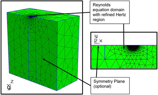
FIGURE 7. Finite element mesh of dimensionless size 60 × 30 × 60 (60 × 60 × 60) with Reynolds domain of size 9 × 3 (9 × 6).
The rheological models used were the Roelands equation for the fluid viscosity as well as the Dowson—Higginson equation for the density (Habchi, 2018). The geometry of the dimples used as microtexture was modelled using a bump function (see Figure 8), which features a smooth decay to zero, thus neglecting pressure spikes due to discontinuous derivatives of the geometry.
The hydrodynamic effect of the dimples can first be understood using circular reference contacts. The parameters for the circular reference contact case can be found in Table 2.
Various dimple depths were compared in a stationary setting with the dimple centered in the contact. The resulting local film thicknesses are shown in Figure 9 and the pressure and film thickness contours in Figure 10.
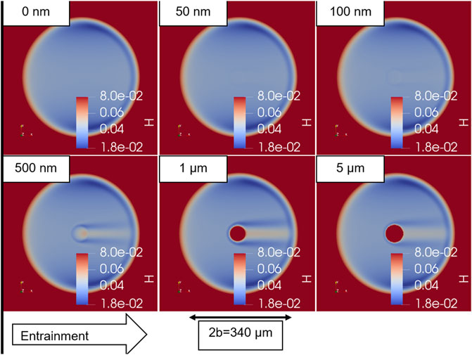
FIGURE 9. Local dimensionless film thickness distribution of microtextured reference contacts with varied depth.
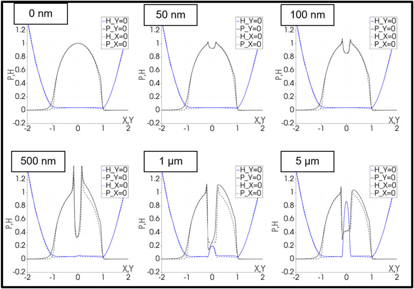
FIGURE 10. Dimensionless film pressure (black) and film thickness (blue) contours in x (i.e., entrainment direction) (continuous) and y (dashed) directions for varied microdimple depth.
As a metric for the dimple performance, the EHL friction force of the calculation cases was computed and then compared. The shear stresses were evaluated using a limiting shear stress relationship (Habchi, 2018). Due to the isothermal conditions assumed, the slide-to-roll ratio enters only via the sliding speeds
In the cases considered above for the calculation of the friction force, it is clear that the microtexture does not have a significant effect on the fluid friction in either case. In the case of pure sliding, the limiting shear stress is reached and has comparable numerical values in all cases. In the case of pure rolling, the shearing due to the gradient in pressure is the dominant term and this is again similar in all cases with the optimum occurring at 100 nm depth. It is important to remember that there are practical limits to this metric because solid and asperity friction is not considered. In practice, the hydrodynamics of the microtextured dimple can lead to more solid-solid contact at the inlet edge. This effect can be seen in the dimensionless film thickness plots in Figure 10, which show the tendency of the inlet edge of the dimple to exhibit a reduced film thickness. This occurs due to a pressure drop in the dimple, which means that directly upstream of the dimple, there is locally insufficient film pressure to deform the surface. The fluid in the contact is following the path of least resistance; as the fluid approaches the dimple, the path of least resistance is to enter the dimple. Thus, fluid is redirected from the edges of the dimple into the dimple, leading to a decrease in film thickness at the edges and directly downstream of the top and bottom edge. Directly downstream of the dimple there is a portion of increased film thickness, which is due to the redirected fluid collecting in the dimple and then being forced out of the dimple outlet.
The degree to which the fluid is redirected is related to the magnitude of the pressure drop it experiences across the dimple boundary. Thus, to reduce the negative effect of the fluid redirection, which in practice leads to increased solid-solid contact, operating parameters that diminish the pressure drop are preferred. Among these operating parameters are a small dimple depth as well as a small pressure-viscosity coefficient of the lubricant.
With this in mind, these beneficial conditions were selected for a calculation with the true flange contact conditions and under the constraints of the chosen manufacturing method based on the one-tooth chamfer. As a minimal value that one would see in practice, a pressure-viscosity coefficient of 6 GPa−1 was chosen, matching e.g., some water-based lubricants. The calculation conditions are shown in Table 4. Due to the near elliptical contact shape determined via FEM, the gap and pressure were approximated in the standard EHL as having undistorted elliptical contours. The surface speeds were computed according to (Kelley et al., 2022). The results are shown in Figures 11–13.

FIGURE 11. (A) The flange pressure distribution computed using FEM (B) The initial Hertzian pressure distribution computed in the EHL solver (axes rescaled to equal length).
Figure 11 compares the initial Hertzian pressure distribution of the EHL calculation to the finite element method computed for the full bearing segment, showing that fair agreement was achieved. The computed film thickness plots are shown in Figures 12A,B. Further results are presented in Figure 13, showing the contours of pressure and film thickness in X and Y directions. It is clear that the parameters chosen minimized the negative effects discussed for the reference contact while still satisfying real-world constraints with respect to the chosen manufacturing method.

FIGURE 12. Dimensionless film thickness (axes rescaled to equal length) for (A) smooth reference case and (B) microdimple with dimensions 750 μm × 100 μm × 10 µm.
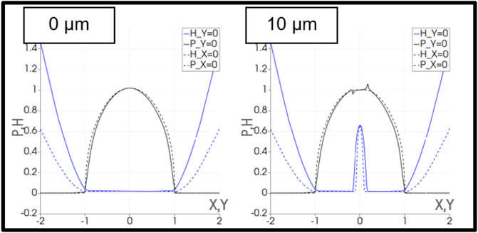
FIGURE 13. Dimensionless film pressure (black) and film thickness (blue) contours in x (i.e., entrainment direction) (continuous) and y (dashed) directions for smooth reference (left) and microdimple with dimensions 750 μm × 100 μm × 10 µm (right).
Based on the results of the calculation method, we are unable to conclude that microtexturing with this manufacturing method would improve friction torque in the bearing by means of hydrodynamics, i.e. by means of the physical phenomena that we intend to model with EHL calculations. In fact, the “deep” microtextures of 10 μm—30 µm depth that are made possible by the manufacturing process worsen the hydrodynamics of the system.
As mentioned in the previous section, there are manufacturing limits in the creation of these microtextures; possible depths range from 1 μm—30 µm on flat samples, with a reduced range of 10 μm—30 µm for a bearing flange surface. Figure 14 shows examples of such microtextures, with Figure 14A) showing the general pattern of microtextures on a flange surface post experiment and Figure 14B) showing an individual measurement of a microtexture on a flat sample, taken using 3D laser scanning microscopy (Keyence VK-X200, Keyence Corporation, Osaka, Japan). According to the EHL simulation of the previous section, microtextures in this depth range do not improve the hydrodynamics of the system. However, the experimental evidence with angular contact ball bearings shows than an improvement in the friction torque is still possible, which therefore most likely is not due to improved hydrodynamic performance.
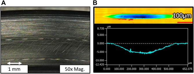
FIGURE 14. (A) Example of a microtextured pattern (90° to radial direction, 10 µm deep) on a flange surface post experiment, × 50 magnification, (B) example of microtexture shape measured on a flat sample using 3D laser scanning microscopy.
The previously shown experimental results of improved frictional torque for microtextured angular contact ball bearings (Figure 2) were obtained under oscillating conditions and with grease lubrication, i.e., conditions that may lead to grease starvation (Wandel et al., 2022). Because we ruled out that this improvement is due to a positive hydrodynamic effect, we may conclude that these types of microtextures most likely function as grease reservoirs. Their positive effect of holding grease in the contact must balance out their negative hydrodynamic effect, meaning that a friction-reducing effect happens solely under grease starvation conditions.
Informed by this analysis, experiments with microtextured bearing experiments were conducted under artificially starved conditions by filling the bearings with LiX-PAO110 grease but only to 10% of the bearing’s free volume, i.e., 8 ml per bearing. A microtextured bearing was always paired with a standard industry bearing in these experiments due to budget and manufacturing constraints. The mounting order was kept constant with the standard industry bearing mounted on the motor side of the test rig. The bearings were mounted in an FE8 test rig and ran for 30 min at +10 RPM and an axial load of 40 kN, i.e., enough time to observe a steady state in the measured torque. The steady-state torques were then compared.
Figure 15 shows a comparison of the torque curves between the reference and a microtextured bearing pair. The microtextures were at a 20° orientation to the radial direction and were 30 µm deep. In the final 10 minutes of the experiment, the bearing pair with one microtextured bearing ran with a 5% reduction in friction in comparison to the reference experiment. There is also a short period of time of less than 3 min at the beginning of the experiment in which the microtextured bearing pair shows a significant reduction in friction.
The feasibility of textured surfaces for roller bearings under certain operating conditions could be proven. In the case of microdimple-texturing of angular contact ball bearings, a reduction of the frictional torque and the wear at the reversal points of the bearings was shown. Because a beneficial hydrodynamic effect was ruled out using an EHL simulation, it can be concluded that the measured reduction in friction and wear is caused by an improvement of grease starvation conditions (Wandel et al., 2022). Thus, microdimple-textured surfaces can enhance the functionality of bearings that are operating under grease starvation conditions, leading to higher resource efficiency. In case of the tapered roller bearings under circumferential movement it is more challenging to achieve beneficial effects due to starvation conditions not occurring due to the operating conditions. It can be stated that:
• The calculation approach proved that the microtextures manufactured in this way via fly cutting or single tooth chamfer cutting are too large for improved hydrodynamic fluid-film build up.
• Experimental investigations prove that there is still a friction-reducing effect of the microtextures, suggesting that they may function as a beneficial grease reservoir under grease starvation conditions.
• This analysis was applied to the tapered roller bearing by running experiments with a reduced grease amount, leading to a slight reduction in friction at the end of the experiment as well as a more significant reduction in friction at the beginning. The torque measurements presented used a sample with a 20° angle to the radial direction and a depth of 30 µm.
• It is noteworthy that in both application cases, the microtexture pattern remained well-preserved after the experiment, despite the harsh experimental conditions leading to significant wear.
Another outcome is that the manufacturing route with a single-tooth chamfer is a feasible option. The benefit of such a one tooth chamfer is the possibility to structure bearings on a conventional manufacturing center. To achieve dimples of smaller size, forming solutions such as precision forging or laser structuring can be applied. The approach of microstructuring by means of single-tooth chamfer results in a high degree of flexibility and low economic effort.
The original contributions presented in the study are included in the article/Supplementary Material, further inquiries can be directed to the corresponding author.
FP and JK worked on design, and experimental studies. JK worked on the calculational approach. GP and FP are supervisor of the projects and give advice within concept and writing.
This work was supported by the Federal Ministry for Economic Affairs and Energy (BMWi) through the “Antriebsstrang 2025: Energieeffiziente Prozessketten zur Herstellung eines reibungs-gewichts- und lebensdaueroptimierten Antriebsstrangs, TP3 Gleichlaufgelenk” project, and also by the German Research Foundation (DFG), through the “Hartfräsen von Mikroschmiernäpfen zur Reibungs-und Verschleißreduktion in hochbelasteten Wälzkontakten” project (project number 407531729). This work was supported by the compute cluster, which is funded by the Leibniz Universität Hannover, the Lower Saxony Ministry of Science and Culture (MWK), and the German Research Foundation (DFG).
The authors declare that the research was conducted in the absence of any commercial or financial relationships that could be construed as a potential conflict of interest.
All claims expressed in this article are solely those of the authors and do not necessarily represent those of their affiliated organizations, or those of the publisher, the editors and the reviewers. Any product that may be evaluated in this article, or claim that may be made by its manufacturer, is not guaranteed or endorsed by the publisher.
1Unless otherwise specified.
Braun, D., Greiner, C., Schneider, J., and Gumbsch, P. (2014). Efficiency of laser surface texturing in the reduction of friction under mixed lubrication. Tribol. Int. 77, 142–147. doi:10.1016/j.triboint.2014.04.012
Brizmer, V., and Kligerman, Y. (2012). A laser surface textured journal bearing. J. Tribol. 134 (3), 031702. doi:10.1115/1.4006511
Etsion, I. (2005). State of the art in laser surface texturing. J. Tribol. 127 (1), 248–253. doi:10.1115/1.1828070
Gachot, C., Rosenkranz, A., Hsu, S. M., and Costa, H. L. (2017). A critical assessment of surface texturing for friction and wear improvement. Wear 372-373, 21–41. doi:10.1016/j.wear.2016.11.020
Ghosh, S., and Abanteriba, S. (2016). Status of surface modification techniques for artificial hip implants. Sci. Technol. Adv. Mater. 17 (1), 715–735. doi:10.1080/14686996.2016.1240575
Gropper, D., Wang, L., and Harvey, T. J. (2016). Hydrodynamic lubrication of textured surfaces: A review of modeling techniques and key findings. Tribol. Int. 94, 509–529. doi:10.1016/j.triboint.2015.10.009
Henry, Y. (2013). Experimental analysis of the effect of pads texturing on fixed geometry hydrodynamic thrust bearings behavior (France: Université de Poitiers).
Hsu, C.-J., Stratmann, A., Medina, S., Jacobs, G., Mücklich, F., and Gachot, C. (2021). Does laser surface texturing really have a negative impact on the fatigue lifetime of mechanical components? Friction 9 (6), 1766–1775. doi:10.1007/s40544-021-0508-2
Hsu, C.-J., Stratmann, A., Rosenkranz, A., and Gachot, C. (2017). Enhanced growth of ZDDP-based tribofilms on laser-interference patterned cylinder roller bearings. Lubricants 5 (4), 39. doi:10.3390/lubricants5040039
Jeng, Y.-R. (1996). Impact of plateaued surfaces on tribological performance. Tribol. Trans. 39 (2), 354–361. doi:10.1080/10402009608983538
Kästner, J. (2013). Methode zur spanenden Herstellung reibungsminimierender Mikroschmiertaschen. Hannover: Thesis, Leibniz Universität.
Kelley, J., Babaalihaghighi, K., Bader, N., Wege, C., Pape, F., and Poll, G. (2022). Application of hertzian theory to torus on plane contacts. Proc. Institution Mech. Eng. Part J J. Eng. Tribol. 236, 2189–2208. doi:10.1177/13506501221074805
Kieckbusch, T. (2017). Strategien zur dynamischen Simulation von Wälzlagern. Kaiserslautern: Dissertation, MEGT.
Komvopoulos, K. (2003). Adhesion and friction forces in microelectromechanical systems: Mechanisms, measurement, surface modification techniques, and adhesion theory. J. Adhes. Sci. Technol. 17 (4), 477–517. doi:10.1163/15685610360554384
Li, K., Yao, Z., Hu, Y., and Gu, W. (2014). Friction and wear performance of laser peen textured surface under starved lubrication. Tribol. Int. 77, 97–105. doi:10.1016/j.triboint.2014.04.017
Pakuła, D., Staszuk, M., Dziekońska, M., Kožmín, P., and Čermák, A. (2019). Laser micro-texturing of sintered tool materials surface. Materials 12 (19), 3152. doi:10.3390/ma12193152
Pape, F., Maiß, O., Poll, G., and Denkena, B. (2017). “Reibungsminderung bei Wälzlagern und Gleichlaufgelenken durch eine innovative Hartbearbeitung,”in Sonderband Abschlußkolloquium „Ressourceneffiziente Konstr.“ SPP 1551, 58. Tribologie-Fachtagung. 21–37.
Pape, F., Neubauer, T., Maiss, O., Denkena, B., and Poll, G. “Tribological investigations of angular contact ball bearings operated under small pivoting angles for production process analysis,” in Proceedings of the 7th International Conference on Tribology in Manufacturing Processes, Phuket, Thailand, July 2016, 190–199.
Pape, F., Poll, G., Katzsch, D., Clemm, O., and Denkena, B. (2022). „Investigations on micro structured surfaces to increase the efficiency of constant velocity joint shafts. Göttingen, Germany: Tribologie Fachtagung.
Sagbas, B., and Durakbasa, M. N. (2013). Effect of surface patterning on frictional heating of vitamin E blended UHMWPE. Wear 303 (1-2), 313–320. doi:10.1016/j.wear.2013.03.023
Taee, M., Torabi, A., Akbarzadeh, S., Khonsari, M. M., and Badrossamay, M. (2017). On the performance of EHL contacts with textured surfaces. Tribol. Lett. 65, 85. doi:10.1007/s11249-017-0871-3
Tauviqirrahman, M., Muchammad, M., Jamari, J., and Schipper, D. J. (2014). Numerical study of the load-carrying capacity of lubricated parallel sliding textured surfaces including wall slip. Tribol. Trans. 57 (1), 134–145. doi:10.1080/10402004.2013.854943
Tremmel, S., Marian, M., Zahner, M., Wartzack, S., and Merklein, M. (2019). Friction reduction in EHL contacts by surfacemicrotexturing–tribological performance, manufacturing and tailored design. Industrial Lubr. Tribol. y 71/8, 986–990. doi:10.1108/ilt-08-2018-0306
Ulmer, H., Dinkelacker, F., Engelke, F., Reithmeier, E., Denkena, B., Göttsching, T., et al. (2015). Microstructuring of thermo-mechanically highly stressed surfaces for application in internal combustion engines,” WTC 2013. Torino, Italy: 5th World Tribology Congress.
Vrbka, M., Šamánek, O., Šperka, P., Návrat, T., Křupka, I., and Hartl, M. (2010). Effect of surface texturing on rolling contact fatigue within mixed lubricated non-conformal rolling/sliding contacts. Tribol. Int. 43 (8), 1457–1465. doi:10.1016/j.triboint.2010.02.002
Wakuda, M., Yamauchi, Y., Kanzaki, S., and Yasuda, Y. (2003). Effect of surface texturing on friction reduction between ceramic and steel materials under lubricated sliding contact. Wear 254, 356–363. doi:10.1016/s0043-1648(03)00004-8
Wandel, S., Bader, N., Schwack, F., Glodowski, J., Lehnhardt, B., and Poll, G. (2022). Starvation and relubrication mechanisms in grease lubricated oscillating bearings. Tribol. Int. 165, 107276. doi:10.1016/j.triboint.2021.107276
Wang, D. (2015). Berechnung der Wälzlagerreibung aufgrund weiterentwickelter rheologischer Fluidmodelle. Hannover: Dissertation, IMKT.
Wheeler, J. (2018). Non-elliptical point contacts: The Torus-on-Plane conjunction. Lyon: Dissertation, INSA.
Willis, E. (1986). Surface finish in relation to cylinder liners. Wear 109, 351–366. doi:10.1016/0043-1648(86)90278-4
The following table contains the assumed nomenclature–the units are those assumed for the weak form, which was derived with SI units. In some other cases, other units are specified.
Keywords: rolling contacts, microdimples, textured surfaces, angular contact ball bearing, tapered roller bearing
Citation: Kelley J, Poll G and Pape F (2022) Investigation of the possible applications for microtextured rolling bearings. Front. Manuf. Technol. 2:1012343. doi: 10.3389/fmtec.2022.1012343
Received: 05 August 2022; Accepted: 26 September 2022;
Published: 20 October 2022.
Edited by:
Yebing Tian, Shandong University of Technology, ChinaReviewed by:
Philipp G. Grützmacher, Vienna University of Technology, AustriaCopyright © 2022 Kelley, Poll and Pape. This is an open-access article distributed under the terms of the Creative Commons Attribution License (CC BY). The use, distribution or reproduction in other forums is permitted, provided the original author(s) and the copyright owner(s) are credited and that the original publication in this journal is cited, in accordance with accepted academic practice. No use, distribution or reproduction is permitted which does not comply with these terms.
*Correspondence: Josephine Kelley, a2VsbGV5QGlta3QudW5pLWhhbm5vdmVyLmRl
Disclaimer: All claims expressed in this article are solely those of the authors and do not necessarily represent those of their affiliated organizations, or those of the publisher, the editors and the reviewers. Any product that may be evaluated in this article or claim that may be made by its manufacturer is not guaranteed or endorsed by the publisher.
Research integrity at Frontiers

Learn more about the work of our research integrity team to safeguard the quality of each article we publish.