 Elham Khanjani1
 Andrea Fergola2
 Joan Antoni López Martínez3
 Simin Nazarnezhad4,5
 Jasmina Casals Terre6*
 Simone Luigi Marasso7,8*
 Behrouz Aghajanloo9*
- 1Department of Chemical and Materials Engineering (CME), Gina Cody School of Engineering and Computer Science, Concordia University, Montreal, QC, Canada
- 2Department of Electronics and Telecommunncations (DET), Politecnico di Torino, Turin, Italy
- 3Department of Engineering Design, Universitat Politècnica de Catalunya ⋅ BarcelonaTech (UPC), Barcelona, Spain
- 4Metabolic Syndrome Research Center, Mashhad University of Medical Sciences, Mashhad, Iran
- 5Tissue Engineering Research Group (TERG), Department of Anatomy and Cell Biology, School of Medicine, Mashhad University of Medical Sciences, Mashhad, Iran
- 6Department of Mechanical Engineering, Universitat Politècnica de Catalunya - BarcelonaTech (UPC), Barcelona, Spain
- 7ChiLab- Materials and Microsystems Laboratory, Politecnico di Torino, Department of Applied Science and Technology (DISAT), Chivasso, Italy
- 8CNR-IMEM, National Research Council-Institute of Materials for Electronics and Magnetism, Parma, Italy
- 9School of Engineering, Faculty of Science and Engineering, Macquarie University, Sydney, NSW, Australia
Microfluidic systems, especially those using capillary forces, have recently attracted considerable interest due to their potential to facilitate passive fluid management in portable diagnostic devices and point-of-care settings. These systems utilize capillary forces to autonomously regulate fluid flow, eliminating the requirement for external power and providing a more straightforward and economical option compared to active microfluidic systems. This review examines the fundamental concepts of capillary-driven microfluidics, emphasizing significant progress in the design of capillary pumps and valves, as well as the influence of surface tension, wettability, and the geometrical configurations of microchannels on the enhancement of fluid dynamics. Furthermore, the review explores other configurations, such as porous and solid substrates, to illustrate their potential for healthcare and biochemical applications. Moreover, the challenges related to managing flow rates and enhancing the reproducibility of devices are addressed, alongside recent innovations designed to overcome these challenges. Capillary systems offer an effective and reliable foundation for developing miniaturized diagnostic instruments, which hold significant potential across various domains, including biological research and environmental monitoring.
1 Introduction
Microfluidics is a scientific and technological discipline that deals with the manipulation and processing of small quantities of fluids, from nanoliters (10−9) to femtoliters (10−15), by using channels with dimensions ranging from tens to hundreds of micrometers (Whitesides, 2006). By miniaturizing traditional laboratory processes, microfluidic systems enhance sensitivity and provide precise control, offering broad application in fields like biological research, diagnostics, and drug development (Guijt and Manz, 2018; Vashist, 2017). These miniaturized platforms, referred to as miniaturized total analysis systems (μTAS) or lab-on-a-chip (LoC), can simplify complex analysis protocols, significantly reduce sample volumes, lower reagent costs while maximizing the information obtained from limited samples.
At the microfluidics scale, fluid dynamics differs significantly from macroscopic phenomena. Surface tension and capillary forces dominate over gravity, enabling unique applications such as passive fluid pumping, droplet generation, and analyte filtration within microchannels (Lei, 2018). To better illustrate the differences between macro and micro-scale, Table 1 is presented (Sackmann et al., 2014). These principles have driven innovations in various fields, including biological synthesis (Ma et al., 2017), chemical analysis (Srivastava et al., 2023), medical treatment (Li et al., 2025), drug development (Liu et al., 2021), and environmental engineering (Wang et al., 2022).
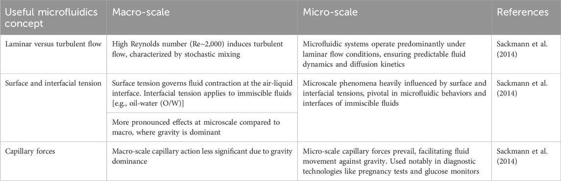
Table 1. A comparative overview of key fluid dynamics phenomena between macro and micro-scales (Sackmann et al., 2014).
Based on the actuation system, microfluidic devices can be classified into two principal categories including active and passive systems. Active systems use external power sources (e.g., syringe pumps and pressure pumps) to drive the fluid flow within the device, thereby enabling the completion of the assay (Aghajanloo et al., 2022). These methods offer excellent control over fluid flow, irrespective of microchannel design or fluid properties. However, their dependence on external equipment limits portability. In contrast, passive microfluidic systems minimize the need for user intervention and eliminates the necessity for bulky external power sources, as the absorbing force is integrated into the chip structure. By reducing the cost of external equipment and providing the possibility of portable use in near-patient diagnostic applications such as point-of-care (POC) (Casals-Terré et al., 2020; Ongaro et al., 2022; Yeh et al., 2017; Karimi et al., 2021; Sachdeva et al., 2020), these systems are among the most promising candidates for POC diagnostic devices, with many of the available systems functioning based on immunoassays. Although passive microfluidic devices may require sophisticated fabrication techniques for more complex applications, their ability to perform simple fluidic functions makes them ideal for fulfilling the “ASSURED” principles (Akbari et al., 2023). This is the World Health Organization’s (WHO) “ASSURED” criteria for POC devices: Accessible, Sensitive, Specific, User-friendly, Rapid, Robust, and Equipment-free and Delivered (to the end user) (Aghajanloo et al., 2023).
However, a significant challenge associated with these devices is difficult controlling of the fluid flow. To date, various types of passive pumping have been developed (Yun et al., 2006; Xu et al., 2020), either based on air transfer, i.e., air solubility (Xu et al., 2020) and air permeability (Wu, 2018) or finger actuated-based (Whulanza et al., 2019; Xu et al., 2015; Liu et al., 2023), diffusion-based or osmosis-based (Chuang and Chiang, 2019; Zhou et al., 2016), gravity-based (Maki et al., 2015), evaporation-based (Yang et al., 2020), and capillary driven pumping (Figure 1) (Ghosh et al., 2020). Among all these approaches, capillary driven has been identified as the most popular and successful pumping method (Aghajanloo et al., 2024). The capillary phenomenon results from the interaction between fluid surface tension, geometry and wettability of the surface of a capillary tube, which is the main driving force behind capillary-guided systems (Zhao and Sun, 2024).
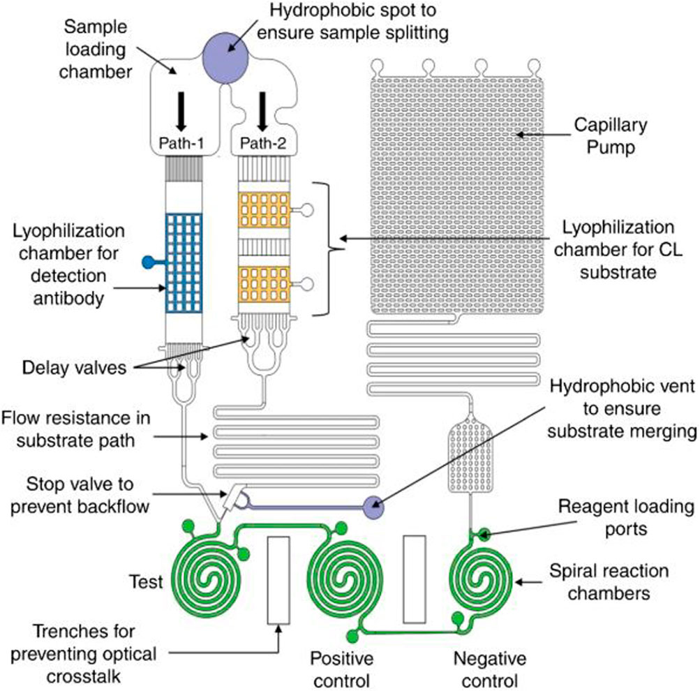
Figure 1. The image is provided as an illustrative example to demonstrate a capillary system. It depicts a microchannel capillary flow assay (MCFA) lab chip designed for chemiluminescence-based sandwich ELISA. The chip features a network of microchannels with hydrophilic surfaces, allowing the serum sample containing the target biomarker to flow through the system without external pumping. As the sample moves through two parallel microfluidic paths, it reconstitutes dried reagents, allowing the antigen-antibody complex to form in the reaction chambers. The chip maintains the necessary sequence for sandwich ELISA, with the reconstituted substrate triggering a chemiluminescent reaction that indicates biomarker concentration (Ghosh et al., 2020). Copyright 2020 the authors. Published by Springer Nature under a Creative Commons Attribution (CC BY) license.
Capillary-guided pumps can be categorised according to several factors including (I) the utilized material of the pump substrate, which can be either porous or solid; (II) the configuration of the chip, which can contain either open or closed channels; and (III) the presence of positive or negative capillary pressure, which determines the ability to absorb fluid within the pump.
1.1 Capillary pressure pumping
Among the applications of capillary pressure, the role of positive pressure is of great importance. This type of pumping can be achieved by the introduction of aqueous droplets with various sizes at the inlets and outlets of the pump. Smaller droplets at the inlet generate higher positive capillary pressure, driving the flow towards the larger droplet at the outlet (Wu et al., 2019; Lee et al., 2020). The speed and direction of flow within the channel can be controlled by adjusting droplet size. This method requires only a device to deliver small amounts of liquid, making it easily applicable in most laboratory settings. However, the challenge of pre-programming fluid flow times often necessitates user intervention to control the assay (Fichera et al., 2024; Najmi et al., 2022). It is worth noting that increasing the generated pressure can be a challenging issue, since it can cause irreversible damage to the platform. Furthermore, if the inlet and outlet droplet sizes are too similar, reverse flow could occur, limiting the reliability of the pumping system (Aghajanloo et al., 2024; Fichera et al., 2024; Najmi et al., 2022). To address these challenges, Berthier et al. developed an analytical model to optimize design parameters for surface tension-driven flows (Najmi et al., 2022). Their work identifies two distinct phases in the behavior of the input droplet: an initial stable flow phase followed by a transition to an unstable regime. The stable flow phase can be extended by periodically refilling the inlet droplet, enabling continuous flow in the microchannel, improving system reliability (Berthier and Beebe, 2007).
Microfluidic systems exploiting capillary pressure can be broadly categorized into three platforms: closed systems, semi-open systems, and open channels. Traditional closed systems consist of completely enclosed channels, whereas semi-open and open channels have open inlets and outlets with an air-liquid interface exposed to the environment. Compared to closed channels, open capillary systems offer several advantages, including fluid accessibility along the entire pathway, ease of fabrication, and ease of surface treatments. Additionally, these open-channel designs reduce the risk of bubble entrapment, which is a common issue in closed channels (Ye et al., 2018; Berry et al., 2019). However, issues such as fluid evaporation, potential fluid loss, and contamination hinder their broader use (Berthier et al., 2019).
To enhance the practicality of open capillary platforms, studies have focused on innovative designs. For example, a V-shaped cross-sectional geometries enhance spontaneous capillary action, making it suitable for handling high-viscosity fluids like blood (Berthier et al., 2015).
Porous capillary pumps (CP) can also play vital roles in lateral flow assays and immunochromatographic strip tests (Casals-Terré et al., 2020). These systems are used to analyse a wide range of biological samples, including urine (Armbruster et al., 2022), whole blood, plasma, sweat, and so on (Koczula and Gallotta, 2016). In these devices, the sample is introduced at the inlet and moves through a porous material to complete the test, allowing for qualitative or semi-quantitative analyses without requiring any expensive equipment. These systems rely on the capillary action of fluids within fibrous materials such as paper (Casals-Terré et al., 2020; Tian et al., 2018; Chen et al., 2012; Jarrett et al., 2020; Mehrdel et al., 2021; Yamada et al., 2017), polyester (Dai et al., 2019), wool, superhydrophobic textiles (Agustini et al., 2021; Lu et al., 2020), cotton thread, knots (Safavieh et al., 2015), and other substrates (Xu et al., 2020; Reches et al., 2010; Jarujamrus et al., 2020; Zhao et al., 2020; Fu and Downs, 2017).
In addition to CPs, various types of capillary valves based on porous materials have been studied to control fluid flow. The integration of these elements can lead to autonomous sequential fluid distribution within these systems (Chen et al., 2012). Porous capillary systems are easy to fabricate and use, cost-effective, and capable of transporting large fluid volumes, making them especially suitable for healthcare applications (Yamada et al., 2017). However, challenges such as reproducibility and flow rate control persist. The heterogeneous flow within selected porous membranes limits further miniaturization and fluid control. Variations in pore size and distribution within the porous structure restrict the resolution, robustness, and reliability of biochemical tests. In microfluidic devices, uneven pore distribution can lead to irregular flow rates, causing delays or variations in sample transport. For example, in saliva-based diagnostic devices, uneven pore structures can lead to inconsistent fluid dynamics and hinder sensitivity (Kumari et al., 2023).
Vinoth et al. developed a microfluidic platform integrated with a porous filtration membrane for monitoring salivary biomarkers (Vinoth et al., 2023). Their findings showed that the heterogeneous pore structure of the filtration membrane effectively prevented the bulkier proteins, mitigating biofouling issues. However, variations in pore size and distribution may still influence fluid dynamics, affecting the overall reliability and sensitivity of such devices (Vinoth et al., 2023). Furthermore, in lateral flow assays, like pregnancy tests, inconsistent pore sizes can hinder the consistent capillary flow of reagents, leading to variability in test results (Kumari et al., 2023; Yetisen et al., 2013). On the other hand, capillary systems based on microchannels minimize contamination risks, require smaller sample volumes, and provide improved flow rate control through structural manipulation. Consequently, flow in solid material-based capillary systems is more predictable and repeatable under controlled conditions.
Despite these advances, controlling the flow has remained the primary challenge in utilizing passive capillary-driven microfluidics. To address this challenge, a variety of materials have been employed in the fabrication of microfluidic chips, including glass, silicon, and polymers (Ren et al., 2013). Most devices are constructed from polymeric materials such as poly (methyl methacrylate) (PMMA) and, notably, polydimethylsiloxane (PDMS) due to their optical transparency and flexibility (Niculescu et al., 2021). In some systems, a combination of solid and porous materials is used to harness the benefits of both structures, enhancing functionality and control within capillary systems. This hybrid approach leverages the predictable flow characteristics of solid channels while utilizing the absorption and distribution properties of porous materials, allowing for more versatile and adaptable microfluidic designs (Kumari et al., 2023; Ren et al., 2013; Niculescu et al., 2021). Furthermore, capillary phenomena are often integrated with other passive and active pumping methods to drive fluid within microfluidic systems more effectively. For instance, Liu et al. combined capillary action with air absorption in degassed PDMS to wick, meter, and mix fluids in microfluidic devices (Liu and Li, 2018). This integration highlights the potential for innovative solutions by combining capillary effects with complementary technologies, expanding the versatility and application of microfluidic systems across various fields. Indeed, recent advancements in capillary-driven microfluidic devices have led to innovative applications across a wide range of biological assays. These devices offer unique advantages over traditional platforms, such as high sensitivity, rapid processing times, and minimal sample requirements, making them ideal options for POC diagnostics and other time-sensitive applications. Table 2 provides a summary of recent research in this area, highlighting the diverse design of capillary devices, various detection targets, sample types, assay turnaround times, and detection limits.
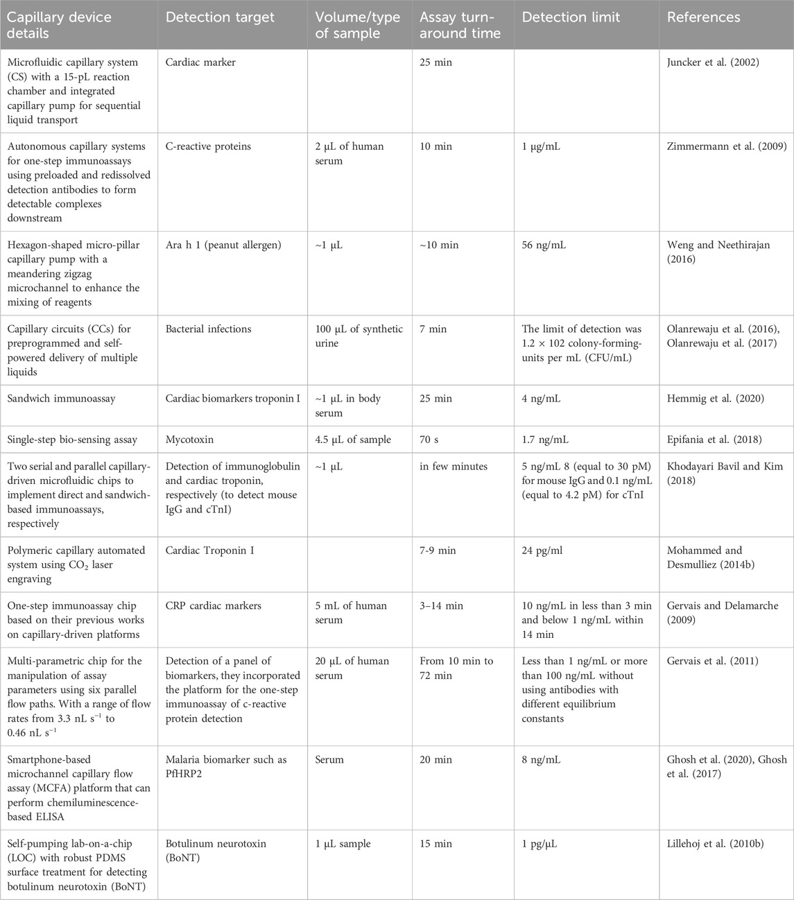
Table 2. A summary of recent research on capillary devices, highlighting their role in advancing biochemical assay efficiency and sensitivity.
Capillary systems are suitable for single or multi-step immunoassays (Desaegher et al., 2025; Chen et al., 2020; Lin et al., 2020). In a recent study, a capillary flow ELISA assay platform was integrated with a smartphone analyser for data display, transfer, storage, and analysis (Ghosh et al., 2020). The study demonstrated that this platform, using chemiluminescence-based detection for the malaria biomarker PfHRP2, achieved a limit of detection (LOD) of 8 ng/mL, which is sensitive enough to detect active malarial infection. Furthermore, the platform can be adapted for other biomarkers, allowing the development of low-cost, portable, point-of-care diagnostic tools with full networking capability (Ghosh et al., 2020).
In another study, Gervais et al. developed a one-step immunoassay chip based on their previous works on capillary-driven platforms (Gervais and Delamarche, 2009). The aim of the study was to detect C-reactive protein (CRP) cardiac markers with concentrations below 1 ng/mL within 14 min by simply injecting a droplet of the sample. The device included a sample collector, a delay valve, a resistor, a reaction chamber, a CP, and vents, which were the main elements of a capillaric circuit (Gervais and Delamarche, 2010; G Navascues Liquid Surfaces, 1979). The results demonstrated that the device was capable of extending the dynamic range of the test and improving the distribution of the detection antibody through a Dean flow mixer. The signal intensity in the reaction chambers varied according to the flow rate, allowing for precise control of the signal with just one sample handling step. This strategy enhanced the effectiveness of the test and reduced the need for sample dilutions or preconcentrations, making the chip more practical for point-of-care diagnostic applications. In another work, they designed a multi-parametric chip for the manipulation of assay parameters using six parallel flow paths for the detection of a panel of biomarkers. They incorporated the platform for the one-step immunoassay of C-reactive protein detection in human serum. The results of the study showed that the microfluidic chip, through its varied flow rates and controlled incubation times, could significantly improve detection sensitivity. In particular, the longer incubation times resulted in a fourfold increase in detection signal for C-reactive protein. This flexibility allows for better optimization of immunoassay conditions and enhances the chip’s versatility for various surface fluorescence immunoassays.
Previous reviews have primarily focused on specific aspects of capillary systems, such as the design of individual components (e.g., capillary pumps and valves) or their integration into diagnostic devices. Nevertheless, a comprehensive understanding of the interplay between key design parameters, such as wettability, geometry, and surface tension, and the overall performance of capillary-driven microfluidic systems across diverse applications remains elusive. Furthermore, critical challenges including precise control of flow rates, enhancing reproducibility, and scaling these systems for broader biomedical and environmental applications persist. This review aims to address these shortcomings by providing a comprehensive analysis of both the fundamental principles and the latest innovations in capillary-driven flow, with a particular focus on addressing persistent challenges and exploring opportunities to optimize device performance.
On this basis, the following sections will examine the fundamental concepts underlying capillary-driven flow in microfluidic devices, including an analysis of the governing equations and key design parameters of primary capillary elements. In addition, the section will explore the various applications of these principles, which are instrumental in enhancing the performance and versatility of capillary microfluidic systems.
2 Fundamental concepts of capillary flow in microfluidic devices
To understand capillary flow in microfluidic devices, it is essential to start with the basic concepts that govern this phenomenon. It is well-known that capillary flow is driven by surface and interfacial forces, determining how fluids move through channels and microstructures at the micron scale. The following sections will discuss these factors in detail.
2.1 Surface tension
Surface tension arises from the cohesive forces that exist between the molecules in a liquid. Within the liquid, molecular attractions are isotropic, with equal and opposite forces acting in all directions. But at the surface, the absence of molecules above creates an imbalance. This imbalance causes molecules to be pulled inward, minimizing the surface area and surface free energy. Surface tension is quantified as force per unit length (N/m).
In microfluidics, surface tension plays a crucial role in determining the behaviour of fluids within microchannels. It is responsible for several key phenomena, including meniscus formation, capillary rise and the spontaneous filling of channels. These effects are fundamental to the control of liquid spreading, movement and stability in microfluidic systems. For example, in diagnostic applications, surface tension ensures precise fluid transport, enabling accurate reactions and measurements. An understanding of and ability to manipulate surface tension enables designers to optimise the performance of microfluidic devices, ensuring consistent fluid flow and robust operation across a variety of applications (G Navascues Liquid Surfaces, 1979).
The typical visual indicator of surface tension is the contact angle (Figures 2A, B), the higher the surface tension the greater the contact angle (Kim et al., 2021). One of the novel technologies that take advantage of the physical phenomenon of surface tension is SAW (surface acoustic wave), this technology provides a method of generating accurate and consistent single or multiple droplets by jetting. This is achieved by directing acoustic energy onto liquid surfaces using transducers, resulting in a technique known as SAW-ADE. By creating a pressure gradient that exceeds the Rayleigh-Taylor instability threshold, and effectively overcomes surface tension. This pressure gradient causes a liquid protrusion that transforms into a jet, which eventually disintegrates into one or more droplets as a result of the Plateau-Rayleigh instability (Figure 2C) (Ning et al., 2023).
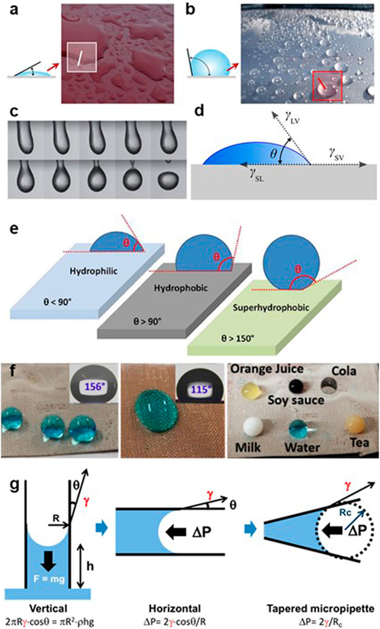
Figure 2. Surface tension: Surface tension primarily depends on the attractive forces between the particles in the liquid, as well as the interactions with any gas, solid, or liquid in contact with it. (A) A low contact angle indicates a low surface tension. (B) With a high surface tension, the energy equilibrium position generates high contact angles. Reprinted with permission from Kim et al. (2021). Copyright 2021 the authors. Published by MDPI under a Creative Commons Attribution (CC BY) license. (C) A series of images illustrating the separation of a 10 μL droplet in pendant state (2 ms between each frame, captured at 500 fps) that has been stimulated by surface acoustic waves (SAW). Reprinted with permission from Ning et al. (2023). Copyright 2023 the authors. Published by MDPI under a Creative Commons Attribution (CC BY) license. (D) The result of the equilibrium between surface interfacial tensions (γ) at the solid (S)-liquid (L)-gas (G) interfaces is the static contact angle (θ) (Neves et al., 2024). Copyright 2024 the authors. Published by MDPI under a Creative Commons Attribution (CC BY) license. (E) Diagram showing the wetting characteristics of surfaces with different contact angles (Liu et al., 2016). Copyright 2016 the authors. Published by MDPI under a Creative Commons Attribution (CC BY) license. (F) Real examples of various liquids on uncoated hydrophobic surfaces (left) and coated superhydrophobic surfaces (centre and right) (Neves et al., 2024). Copyright 2024 the authors. Published by MDPI under a Creative Commons Attribution (CC BY) license. (G) Capillary Pressure: Three examples of this phenomenon equilibrium position with water-air interface. The upward movement of water in a vertical capillary tube. In the horizontal capillary pipette filled with water. In the horizontal capillary tapered pipette filled with water. Copyright 2019 the authors. Published by MDPI under a Creative Commons Attribution (CC BY) license (Needham et al., 2019).
2.2 Wettability
Wettability refers to a liquid’s ability to adhere to a solid surface or another liquid substrate. It is a crucial concept in microfluidics because it determines how fluids interact with surfaces, influencing flow behavior and the efficiency of fluid transport in microchannels.
To quantify wettability, the spreading parameter S is often used, defined by Equation 1:
Wherein γ represents the surface tensions at the solid/gas (γSG), solid/liquid (γSL), and liquid/gas (γLG) interfaces. This parameter is particularly important in devices where precise fluid control is essential, such as point-of-care diagnostic chips (Figure 2D).
In this context, the contact angle is a key parameter in determining wettability. It is the angle formed between the tangent to the surface of the liquid and the surface of the solid at the line of contact between liquid, gas and solid. The static contact angle (θ) is given by Young’s equation (Equation 2):
Wherein θE is the equilibrium contact angle. This equation establishes the relationship between surface tensions at the solid-liquid-gas interfaces, providing insights into how a liquid interacts with a surface. This understanding is vital for predicting and optimizing fluid behavior in microchannels, particularly in applications where rapid and uniform fluid distribution is essential.
Surfaces are categorized based on their contact angle (Figure 2E). When the spreading parameter S > 0 and θ < 90°, the surface is considered highly wettable, or superhydrophilic. For S < 0 and θ < 90°, the surface is hydrophilic but exhibits reduced wettability. Conversely, when S < 0 and θ > 90°, the liquid forms distinct droplets, signifying a hydrophobic surface. Finally, when θ > 150° the surface is considered superhydrophobic. These classifications are crucial for tailoring surface properties to specific microfluidic applications. In Figure 2F, it can be seen how surface coating can affect to wettability. Authors developed fluorine-free superhydrophobic coatings on copper mesh by utilizing a combination of PDMS and a multi-walled carbon nanotube/zinc oxide (MWCNTs/ZnO) composite through dip-coating methods. The image on the center shows coloured water in contact with the uncoated surface (naturally hydrophobic), while the other two images show the effect of the coating on the coloured water and also on other liquids (clearly superhydrophobic).
Under dynamic conditions, contact angles become more complex. For example, as a droplet moves across a non-ideal surface, the advancing front (θa) and receding front (θr) often differ due to surface irregularities or variations in wettability. This phenomenon, known as contact angle hysteresis, can impact the consistency of fluid flow. If not properly accounted for, hysteresis can introduce errors in fluidic performance, potentially affecting the accuracy of diagnostic readings or other applications requiring precise control.
It is worth noting that a fluid’s contact angle increases with the increase in its flow rate. To formulize the capillary phenomena, Bracke et al. proposed an equation (Equations 3, 4) to calculate the contact angle with the use of the capillary number and the velocity of the fluid (Safavieh et al., 2015; Bracke et al., 1989):
In this equation, U denotes the filling front velocity, which is the speed at which the liquid front progresses through the microchannel. θa is the static advancing contact angle, and θd is the dynamic advancing contact angle. This dynamic perspective is crucial for designing microfluidic platforms that enable controlled fluid delivery, particularly in healthcare and environmental monitoring.
2.3 Capillary pressure
Capillary pressure is a pivotal force in microfluidic devices, where the small dimensions of the channels amplify the effects of surface interactions. This phenomenon, first explored by Washburn (1921) in the 1920s, arises from the adhesive forces between liquid molecules and the capillary wall, combined with the cohesive forces among the liquid molecules themselves. These interactions create a concave meniscus at the liquid’s surface, which draws the fluid upward due to the negative (suction) capillary force. This upward movement is a key mechanism enabling fluid transport in microchannels.
Capillary rise of water in a vertical capillary tube occurs when the tube is immersed in a liquid, causing the meniscus to rise against gravity to a height (h) above the surrounding liquid surface. At equilibrium, this height is determined when the forces are balanced according to the Young-Laplace equation, which takes into account the effects of gravity and surface tension (Figure 2G). In the horizontal capillary pipette filled with water, the water will flow into the horizontal capillary until it is opposed by a counterforce, such as pressure on the back end of the pipette, to hold it in position or push it back (Figure 2G). With a tapered micropipette, the position of the meniscus is outwards, requiring a sequence of increasing applied pressure to force the liquid surface downwards along the taper (Figure 2G) (Needham et al., 2019).
The pressure created by these capillary phenomena is described by the Young-Laplace equation, which considers the surface tension of the liquid, the geometric features of the channels (such as width, height, and length), and the surface chemistry (wettability) of the solid wall. In rectangular channels, common in microfluidic devices made through photolithography or rapid prototyping methods, the Young-Laplace equation (Equation 5) is expressed as:
Wherein P is the capillary pressure, and γ is the surface tension of the liquid. The angles θt and θb represent the contact angles at the top and bottom surfaces of the channel, respectively, while θl and θr are the contact angles at the left and right sides of the channel. The height and width of the channel are denoted by ℎ and w, respectively.
In microfluidic systems with wettable surfaces, where the contact angle θ is less than 90°, a negative capillary pressure pulls the fluid into the channel. This mechanism is fundamental to the operation of CPs. For optimal performance of capillary circuits, a contact angle θ of less than 60° is preferred. However, the actual effective capillary pressure can be lower than the predicted value due to discontinuities or imperfections in the capillary paths, which can affect the fluid flow dynamics.
2.4 Flow rate
Understanding and predicting flow rates in microchannels is vital for designing capillary systems that operate reliably across a range of conditions. This flow rate can be described using the Navier-Stokes equation. A pressure-driven, steady-state, fully developed laminar flow in a circular channel (Hagen-Poiseuille flow), is given by Equation 6:
Wherein Q is the volumetric flow rate, a is the radius of the channel, η is the dynamic viscosity of the fluid, L is the length of the channel, and Δp is the pressure difference across the length of the channel.
In typical microfluidic fabrication, channels are often rectangular. Therefore, for rectangular channels, the flow rate Q is described as (Equation 7):
In these expressions, ℎ is the channel height, w is the channel width, and the summation accounts for the contribution of multiple modes in the rectangular geometry.
The equation (Equation 8) can be approximated by:
When the ℎ/w ratio converges to zero, this approximation approaches the exact solution. For the case where ℎ = w, the deviation from the exact solution is about 13%, and for ℎ = w/2, it decreases to 2%, showing that the approximation aligns well with exact results (Bruus, 2008). The sensitivity of flow rates to channel dimensions, as highlighted by this approximation, underscores the need for precise fabrication techniques in microfluidic design, particularly for applications like biochemical assays where consistent flow rates are essential to ensure uniform reagent mixing and precise reaction times. Additionally, the equation offers valuable insights into the impact of design modifications, such as reducing h/w ratios, which can enhance flow stability. This improved control overflow dynamic is vital for optimizing assay conditions, ensuring reproducibility, and enhancing the overall accuracy of diagnostic systems.
It is worth noting that Zimmerman et al. have presented a first-order approximation for the flow rate as the following (Equation 9) (Zimmermann, 2009):
Here, Rℎ is the hydraulic radius, and ΔP is the pressure difference across the microchannel, approximated by the pressure at the liquid-air interface, as described by the Young-Laplace equation for capillary pressure in a rectangular channel.
On the other hand, Song et al. proposed an alternative equation (Equation 10) for the average fluid flow velocity within the capillary channel (Saha et al., 2009; Song et al., 2011):
Where
These two sets of equations are utilized in various studies. Although both yield approximately similar values for fluid parameters in capillary channels, some differences may exist. Mohammed et al. compared experimental results for fluid flow rates within capillary circuits with the equations proposed by Zimmerman and Song, demonstrating that Song’s equation is more accurate, particularly for larger channel ratios (Mohammed and Desmulliez, 2014a). In their calculations for pump filling, they treated the pump as a single channel with a length equal to the sum of the interconnected channels within its structure. They found that Zimmerman’s equations are better suited for smaller channel ratios. In summary, these equations appear to offer different approaches to model fluid flow in capillary channels. Zimmerman’s equation tends to be more appropriate for smaller channel ratios, while Song’s equation provides better accuracy for larger channels.
This comprehensive investigation underscores the importance of selecting appropriate theoretical models for different channel geometries and provides a useful comparison between theoretical predictions and experimental observations in microfluidic systems.
To further understand and optimize fluid flow in microfluidic systems, researchers often turn to electrical analogies. Considering electrical analogies for capillary circuits, the hydraulic resistance of a rectangular microchannel can be expressed as follows (Equation 11):
Wherein ΔP is the pressure difference, Q is the flow rate, η is the fluid viscosity, w and ℎ are the width and height of the channel, respectively, and L is the channel length.
The overall resistance of the channel is determined by its smallest cross-sectional area. Unlike the constant resistance in electronic circuits, flow resistance increases as the channel fills, while capillary pressure remains constant for a fixed cross-section. The CP’s contribution to the overall resistance is negligible due to the interconnected nature of its structure. Thus, a constant flow rate can be maintained once the flow reaches the CP. However, the flow resistance and consequently the flow rate can be adjusted by changing the dimensions of other circuit elements, such as chambers, vias, and valves. Programmable fluid flow within a microfluidic channel can be achieved by manipulating its geometric dimensions. This approach is advantageous for applications requiring specific timing or precise flow rates.
In recent years, several studies have expanded upon these foundational concepts by developing innovative designs and models to optimize capillary systems. For instance, Safavieh et al. explored novel capillary pump architectures aimed at improving fluid management within microchannels (Safavieh et al., 2015). Their work highlights the development of two CP designs that mitigate bubble entrapment and achieve consistent flow rates. These designs, known as the serpentine pump and the leading-edge pump, use variable gap sizes between posts to direct the flow and avoid air bubbles, which can disrupt the consistency of fluid metering. The gap between adjacent posts in two subsequent rows (W1) is larger than the gap between two columns (W2). The posts are oval-shaped to function as a temporary stop valve, preventing liquid from leaking into the gap between rows and to avoiding sharp edges that increase the bubble entrapment. The oval shapes of the posts reduce bubble entrapment by eliminating sharp edges. They suggest three strategies to increase the reliability of temporary stop valves between the posts. 1. Increasing the W1/W2 ratio, 2. Decreasing the hydrophilicity of the sealing over the pump structure, and 3. Increasing the capillary pressure in each row to wick the liquid more robustly.
The serpentine CP channels liquid along a winding path, while the leading-edge CP channels it along one edge, allowing the fluid to fill row-by-row. In serpentine CP, the capillary channels follow a serpentine or zigzag shape, which slows down the fluid flow and increases the contact area between the liquid and the channel walls. This design optimizes capillary action by increasing the surface area available for the liquid to “stick” to, thus enhancing the fluid’s movement through the channel.
In the second variant, leading-edge CP, the smaller gap distance of microarrays from one of the edges creates higher capillary pressure and guides the fluid parallel to that specific edge. From the leading edge, the parallel fluid flow moves between the rows and fills the entire pump immediately. Safavieh et al. studied 0–45° angled structures for both CPs and indicated that in 45-degree angled CPs, the liquid’s bypass and consequently air entrapment have the minimum susceptibility. They also demonstrated that a gradient in pressure and flow rate can be generated by adjusting the gap size between microposts, thus achieving precise control over the fluid dynamics within the CP. This deterministic guidance of the filling front enables robust management of flow rate and volume, making these designs particularly suitable for applications requiring high accuracy. Figure 3 demonstrates the serpentine and the leading-edge CP.
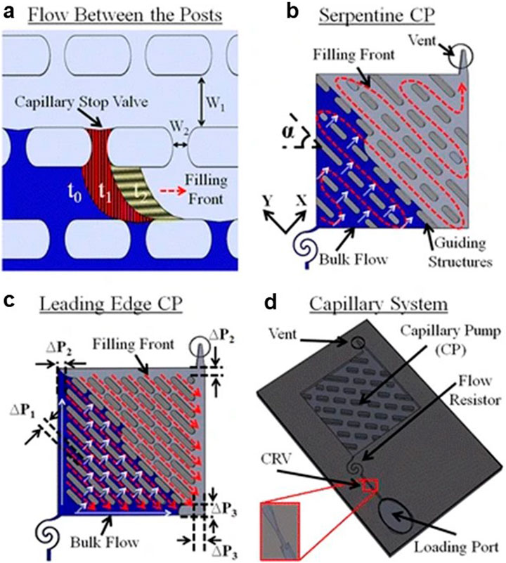
Figure 3. Schematics of serpentine and leading-edge CPs with arrays of posts. (A) Shows the migration of the flow between the posts from time t0 to t2. (B) Serpentine CP. (C) Leading-edge. (D) A capillary system containing a loading port, a CRV, and a flow resistor (Safavieh et al., 2015). Copyright 2019 the authors. Published by MDPI under a Creative Commons Attribution (CC BY) license.
Similarly, Tamayol et al. investigated the pressure drop across ordered arrays of cylinders embedded within microchannels (Tamayol et al., 2013). Their research provided valuable insights into how geometrical parameters, such as cylinder diameter and spacing can impact flow resistance. Using both experimental and analytical methods, they developed models that predict flow resistance in the creeping flow regime. Their findings revealed that the pressure drop can be minimized by optimizing the diameter and spacing of micro-cylinders while desired surface-area-to-volume ratios were maintained. Tamayol’s work involved fabricating silicon/glass samples and conducting pressure drop measurements across various nitrogen flow rates. Their results indicated that the porous medium approach offers a broad applicability, while the variable cross-section technique excels in denser cylinder arrays. These findings underscore the importance of channel architecture in determining flow resistance and highlight the potential for optimizing the design of microchannel to achieve specific flow characteristics.
Another interesting approach is the integration of electrical analogies with advanced geometric designs, enabling significant advances in microfluidic systems. By understanding and manipulating flow resistance and capillary pressure, researchers can design programmable CPs with precise control over fluid dynamics. The innovative designs developed by Safavieh and Tamayol establish robust frameworks for enhancing microfluidic applications, paving the way for more efficient and reliable passive microfluidic systems (Safavieh et al., 2015; Tamayol et al., 2013).
3 capillary circuit elements
A capillary system is composed of several essential elements including (I) a loading pad to introduce fluids, (II) a reaction chamber for assays, and (III) a CP capable of driving liquid through the system via capillary forces. The process begins when fluid is placed on the loading pad and fills the circuit by displacing air through vents. These vents, which are relatively large conduits connected to the atmosphere, are designed to be hydrophobic, preventing liquid entry unless required for specific applications (Olanrewaju et al., 2018).
In the capillary systems, microchannels serve as pathways for fluid transport, functioning similarly to electrical lines in circuits. Fluidic resistors, which are microchannels with constrained cross-sections, act analogously to resistances in electrical circuits. The flow resistance in these channels is inversely proportional to the fourth power of the channel’s radius (R⁻⁴) in the case of circular cross-sections. Thus, even a small dimensional change can significantly impact the overall resistance of the circuit, making precise control of these dimensions crucial for optimal system performance.
In a pioneer work, Olanrewaju et al. (2018) introduced various capillary elements and modelled them using an electrical circuit analogy. The CP was represented as a voltage source, producing an almost constant pressure throughout the circuit. The overall resistance of a CP was determined by modelling it as a network of parallel and serial resistors. This is similar to the electrical approaches for deriving the total resistance of a circuit (electrical analogy) (Rousset et al., 2022). They developed a library of capillary elements which can be combined to make complex capillary circuits. In this approach, the microchannels represent electrical lines in an electrical circuit, and the trigger valve function like diodes with unidirectional behavior. Classic valves such as CRV (Capillary Retention Valve) and RBV (Retention Burst Valve), which will be elaborated on later, were represented by bar symbols indicating their braking pressure. In the case of the CRV, this pressure is being infinite.
4 Capillary pumps (CP)
Capillary pumps (CPs) are crucial components in capillary circuits, positioned at the end of capillary systems (CS), where they generate the highest capillary pressure. This pressure difference drives fluid motion through the system, functioning analogously to a voltage source in an electrical circuit. Indeed, the CP creates negative pressure via capillary forces due to the difference between the wetting meniscus in the pump and the dewetting meniscus at the injection port. This mechanism enables precise fluid control, making CPs an essential element in microfluidic devices.
A useful analogy is to consider CPs as batteries. They store energy in the form of a dry surface or material that achieves a lower energy state upon hydration. As the material hydrates, energy is released, driving fluid movement within the connected microfluidic system (Probstein, 1989). The dynamics of this process can be quantified using the Washburn equation (Equation 12), which relates the position of the wetted front (x) to the square root of time (t) (Washburn, 1921):
Here,
4.1 Design considerations and flow resistance
A CP is often preceded by a meandered channel, which acts as a flow resistance element. Together, the pump and this resistance allow for precise flow rate control. Assuming constant capillary pressure within the pump, the flow rate becomes a function of the flow resistance. The CP itself is designed to have negligible flow resistance compared to other circuit elements—often two to three orders of magnitude smaller. This design allows the flow rate to be adjusted by modifying the upstream resistance without altering the pump’s structure.
In addition to resistance, the geometry and material properties of the pump structure play a critical role. Porous materials in CPs can be approximated as a collection of cylindrical capillaries. According to the Hagen–Poiseuille equation (Equation 13), the resistance (R) of each capillary is:
For a porous material, its resistivity (
This framework allows for a detailed understanding of how capillary pressure, internal resistivity, and porosity influence the flow rate in porous materials.
4.2 Capillary pressure and capacity
An attractive force between the capillary wall and liquid generates capillary pressure (
CP capacity, defined as the maximum liquid volume intake, is determined by the pump’s geometry and material properties. For rigid porous materials, capacity is proportional to porosity, while for hydrogels, capacity is characterized by the swelling ratio. Hydrogels, which lack well-defined pore sizes, can achieve high volume efficiencies, sometimes exceeding 99.5%. However, swelling alters their resistivity and suction pressure, complicating flow control compared to rigid porous materials (Ogawa et al., 1993).
4.3 Applications and advanced design features
Capillary pumps serve diverse purposes in microfluidic circuits, including triggering reactions, pumping fluids, and metering precise fluid volumes. They also function as waste reservoirs in biological assays. The shape, geometric parameters, and wettability characteristics of CPs can be tailored to control the liquid filling front, ensuring consistent flow and minimizing bubble entrapment. For example, covering the CP can prevent contamination and evaporation, though evaporation-based methods may introduce challenges in flow regulation.
When designing CPs, it is important to balance pressure and flow rate depending on the connected device’s resistance. For systems with significant fluidic resistance, small pore sizes are advantageous due to their ability to generate higher pressures. Conversely, in systems with low resistance, larger pores optimize flow rate by reducing internal resistance. This trade-off resembles the maximum power transfer principle in electrical circuits.
4.4 Types of capillary pumps
Capillary pumps can be categorized into four main types (see Figure 4), each with unique features and applications:
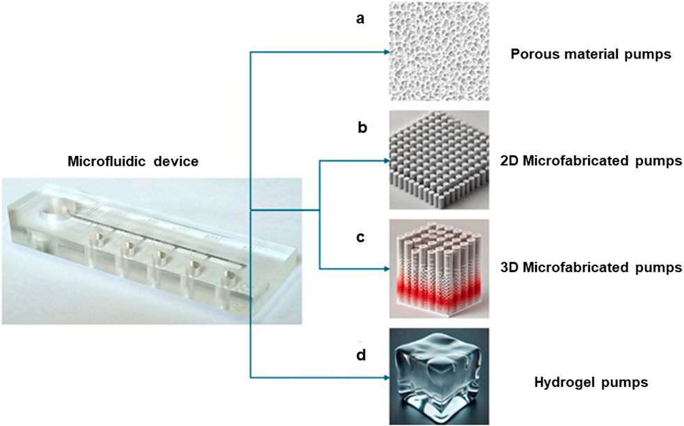
Figure 4. Various types of capillary pumps. (A) Porous Capillary Pumps: These use materials with interconnected pores to move the fluid. (B) 2D Microfabricated Capillary Pumps: Composed of two-dimensional microstructures, such as microchannels or patterned surfaces, designed for precise flow control. (C) 3D Microfabricated Capillary Pumps: Use three-dimensional microstructured arrays to enhance capillary pressure and reduce air trapping. (D) Hydrogel Capillary Pumps: Utilize the swelling of materials to absorb large volumes of fluid with high efficiency. Reprinted from Aghajanloo et al. (2024). Copyright 2024 the authors. Published by AIP Publishing under a Creative Commons Attribution (CC BY) license.
4.4.1 Porous Capillary Pumps
Porous CPs utilize materials with interconnected pores, such as paper or membranes, to drive fluid movement (see Figure 4A). These designs are simple and cost-effective, making them suitable for disposable devices. However, they may exhibit variable flow rates due to uneven pore sizes or clogging. In their work, Salafi et al. developed a portable and low-cost smartphone-based microscopy platform for real-time particle detection in microfluidics, incorporating a paper pump to drive fluid movement. This approach enhances the practicality of microfluidics for real-time point-of-care diagnostics, with a 94% accuracy in particle counting (Salafi et al., 2019).
4.4.2 Microfabricated 2D capillary pumps
These pumps consist of two-dimensional microstructures, such as microchannels or patterned surfaces, designed to achieve precise flow control (see Figure 4B). They are ideal for applications requiring high reproducibility and stability in microfluidic circuits. Lillehoj et al. developed a self-pumping lab-on-a-chip system using PDMS, where capillary-driven flow in 2D microchannels enabled rapid and autonomous detection of toxic substances like botulinum neurotoxin. This system demonstrates the effectiveness of 2D capillary pumps in real-time, portable detection applications (Lillehoj et al., 2010a).
4.4.3 Microfabricated 3D capillary pumps
Extending the concept of 2D designs, 3D CPs use microstructured arrays to create interconnected flow paths (see Figure 4C). This approach enhances capillary pressure and minimizes air entrapment. Studies by Zimmerman et al. have highlighted the advantages of 3D designs, such as reduced pinning effects and improved uniformity in flow rates (Zimmermann et al., 2007).
4.4.4 Hydrogel capillary pumps
Hydrogels offer a unique advantage with their high swelling ratio and ability to intake large fluid volumes. While they provide high efficiency, their swelling behavior can complicate flow control and impact device performance (see Figure 4D). Akyazi et al. developed cholinium-based poly(ionic liquid) hydrogels for use as passive pumps in microfluidic paper-based analytical devices (μPADs). These hydrogels effectively manipulate fluid flow by directing it preferentially, improving water retention by a factor of nine compared to standard μPADs, and significantly extending the operational lifetime of the device. This highlights the potential of hydrogel-based capillary pumps for enhancing fluid management in microfluidic systems (Akyazi et al., 2018).
4.5 Main design of capillary pumps
Among the key designs for the internal structure of capillary pumps, the simplest involves a microchannel extended just enough to hold the required fluid volume. Another design involves parallel channels, known as tree line pumps, in which the fluid is drawn through a branching tree-like network of capillary channels (Figure 5A). The liquid enters through the main channel and then is guided through smaller branches. The advantage of such designs is their high surface area and enhanced capillary action due to the multiple, closely spaced smaller channels, which can improve the pumping efficiency. In these pumps, increasing resistance as the filling front progresses results in a decreased flow rate. Tree line pumps can provide regions with different capillary pressures, allowing for multiple flow rates. When one branch fills, it disconnects from the fluid flow, isolating its resistance from other branches (Zimmermann et al., 2007).
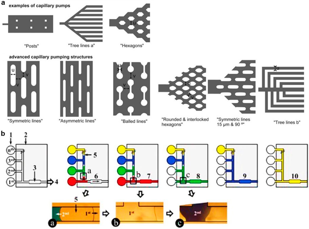
Figure 5. (A) Some examples of capillary pump patterns. The characteristic dimensions of the components that produce capillary pressure within a capillary pump can be modified by altering the density (referred to as Posts), the geometry (referred to as Hexagons), the spatial arrangement, and the continuity (referred to as Tree lines) of these structures. All capillary pumps are illustrated with the filling direction oriented from left to right. Reproduced with permission from Zimmermann et al. (2007). (B) Sequential liquid delivery and some capillary valves. In multiple inlet capillary devices, the air trapped between the liquid plugs can act as a check valve, preventing the liquids from mixing. In this approach, air trapped in a capillary tube can be used to create sequential fluid flow. Reproduced with permission from Novo et al. (2013).
Microstructured CPs offer an effective design alternative. These microarrays create parallel interconnected flow paths, enhancing capillary flow with a high surface-to-volume ratio. This design results in a high and stable flow rate in the circuit, minimizing air entrapment and reducing flow resistance (Zimmermann et al., 2007). The structure of microarrays or meshes also decreases the likelihood of clogging and flow stoppages due to their interconnected fluid paths, making them robust designs for CPs. Moreover, they require a reduced total footprint for the pump. Zimmerman et al. investigated various microarray shapes within a CP (Zimmermann et al., 2007). The gaps between posts in a row act as pinning sites, serving as Delay Valves (DV) that impede the progression of the filling front. Rounded micro-post peripheries minimize fluid pinning, enhancing flow performance. The CP with the smallest characteristic dimension generates the largest flow rate in the CS. In their study, the “Symmetric Line” design with minimal dimensions exhibited the highest calculated flow rate, yet also showed the most significant discrepancy between theoretical and experimental results was due to fluid delays at pinning sites. Conversely, the interlocked characteristic of the hexagon design results in a more uniform flow rate because of fewer pinning sites. Based on experimental data, they proposed a correction factor for the flow resistance of the pump, using the formula (Equation 16):
Wherein v is the lateral and forward distance between the arrays.
It should be noted that the ΔP calculated from theoretical equations might show a larger value than the actual one obtained from experiments. This discrepancy arises from the discontinuities in the pump-filling channel caused by gaps between the posts. To ensure sufficient capillary pressure for the circuit, the CP can be connected to the rest of the CS using a gradually expanding configuration. Bubble entrapment, known as corner flow, can occur when the liquid filling front moves faster along one side of the CP and reaches the outlet before completely filling it. This issue can cause inaccuracies in metering and deviations from expected behavior and timing, such as incubation times in bioassays. Additionally, entrapped air unpredictably increases channel resistance, becoming significant when the contact angle (θ) is below 30°. Therefore, the optimal working contact angle for capillary devices is between 30 and 60°. Zimmerman et al. used micro-post CPs with indented side walls to slow down fluid progression along the peripheral edges, minimizing air entrapment (Zimmermann et al., 2007) However, this strategy is not always effective, as the filling front may bypass some rows, entrapping bubbles within the channel. When pumps are connected in series, this problem becomes more pronounced and critical, especially in assays requiring different flow rates at various stages. Zimmerman et al. also designed an “arc-shaped” bridge at the end of each pump to minimize fluid bypass risk. This structure acts as a delay valve, reducing the likelihood of bubble entrapment but weakening the pump’s suction pressure. Increasing the bridge size guides fluid more predictably and aims to prevent incomplete pump filling. However, it can fail when weaker pumps are connected. These hierarchical bridges are more suitable when connecting a slow pump to a fast one. For highly hydrophilic surfaces, adding flow resistance after arc bridges can further prevent fluid bypass by slowing the filling front’s progression. However, adding these elements will increase the device complexity and uncertainty, potentially leading to CP failure.
5 Sequential liquid delivery
While air entrapment can pose challenges in CPs, it can also serve a valuable purpose in systems with multiple inlets by acting as a fluid sequencer (Figure 5B). The trapped air prevents liquids from mixing by acting as a barrier, ensuring that different solutions from various inlets reach the reaction chamber in a specific sequence. In this setup, the CP draws the sample from the closest inlet, with the trapped air effectively blocking other flows until the initial delivery is fully completed. It should be noted that the entrapped air adds high flow resistance to the circuit which can increase the chance of flow stoppage in such systems. The required fluid volume to reach the reaction chamber should account for evaporation at the corresponding inlets before the liquids are drawn, which can be controlled by adjusting environmental temperature and humidity (Novo et al., 2013).
Another method involves designing RBVs with programmed thresholds for the addition or removal of the solutions in a sequential manner. Safavieh et al. designed a circuit consisting of RBVs of varying capacities and CRVs to encode the delivery of liquid in a predetermined sequential manner (Figure 6A). As mentioned before, the flow resistance preceding the CP prevents fluid bypass due to the large pressure of the pump to ensure that all the arms are filled before reaching the CP. The hysteresis between advancing and receding contact angles with the surface introduces uncertainties in determining the burst pressure of the valve. Thus, it is recommended to choose the CP way stronger than the RBVs, and also consider a significant difference between valves’ threshold to ensure the reliability of the circuit (Safavieh and Juncker, 2013).
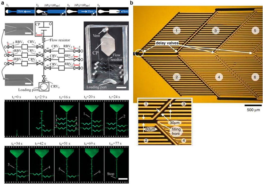
Figure 6. (A) RBVs are an adaptation of CRVs, both of which result from a localised reduction in channel cross-section that inhibits fluid drainage due to increased capillary pressure. Whereas CRVs are designed to hold liquid indefinitely, RBVs act as a release valve when the capillary pressure exceeds a certain limit. Consequently, a series of RBVs with progressively higher thresholds can be used to regulate the timing of fluids delivery. Reproduced with permission from Safavieh and Juncker (2013). (B) Because the velocity of a filling front in a wide microchannel is lower than the velocity of a filling front moving in a narrow microchannel, delay valves (DV) retard one of at least two filling fronts by increasing the size of the meniscus of the filling front and thereby reducing its capillary pressure. A delay valve changes the ratio of the flow rates of two parallel flow paths. Reproduced with permission from Zimmermann et al. (2008).
Zimmermann et al. (2008), proposed using Delay Valves (DVs) to manage the sequential addition of reagents. DVs ensure that each circuit element is entirely filled before moving to the next. These strategies for sequential filling are mostly applicable in the control of timing for bioassays steps, such as incubation and rinsing. Once a channel fills, it exits the circuit and no longer contributes to overall flow resistance, keeping resistance low. This feature helps maintain low system flow resistance. Ultimately, it is possible to tune the flowrate by altering the resistance value positioned before the pumping system. Authors showed that DV (Figure 6B), could significantly reduce the velocity of a filling front by putting it in competition with another filling front advancing in a relatively higher capillary pressure zone.
6 Capillary systems with constant flow rate
Although the microstructure pump’s own resistance is often ignored by simplifying the capillary pressure as a constant suction value, it is feasible to compensate for increased pump resistance by gradually varying the width of the parallel channels to increase the capillary pressure. Figure 7 illustrates this approach to compensate for variations in flow rate: Guo et al. used a narrow air passage as a prevailing resistance that managed to maintain a constant flow rate independent of the viscosity of the liquid (Guo et al., 2016). They also demonstrated that, by using a characterized liquid downstream, another unknown liquid could be drawn with a constant flow rate, regardless of its viscosity and surface energy (Guo et al., 2018).
Figure 7. CP with a constant flow rate in time and independent of the sample viscosity and sample surface energy. Its design facilitates the capillary imbibition of a well-characterised pump liquid into the downstream section of the pump, which in turn draws the unknown sample liquid into the upstream section. The geometry of the downstream pump is designed to exert a Laplace pressure and fluidic resistance on the sample liquid that significantly exceeds that of the upstream geometry, minimising the effect of the unknown sample liquid on the flow rate (Guo et al., 2018). Copyright 2018 the authors. Published by Springer Nature under a Creative Commons Attribution (CC BY) license.
In 2014 (van der Wijngaart, 2014), using a theoretical approach, defined the geometric parameters for CP with constant flow rate. Other authors like Madadi et al. (2014) studied the effect of pillar arrangement and its shape on flow resistance. In some immunoassays, precise control over the filling time of the fluid is crucial. On the other hand, biological fluids can vary in viscosity, causing fluctuations in pump flow rate. To address this, the proposed CP design consists of a capillary with a narrowed air vent downstream, where gas viscosity dominated over the effect of liquid’s viscosity and enforced a constant flow rate for any liquid. Authors developed a theoretical model and validated it with experimental analyses for circular CPs, which can also be applied to rectangular cross-sections. They also modified the design to achieve precise flow rate control, independent of both the sample’s viscosity and its surface energy. They introduced the “pump liquid” to the pump first, the pressure of which was much higher than the “sample liquid’s pressure.” The specific Design of the device ensured that the capillary pressure and the viscosity of the pump liquid plug dominated the entire device. Thus, the pump’s liquid encodes the whole pump’s flow rate. A flow restrictor between two parts of the pump dominates the flow resistance of the whole pump. Consequently, the pressure drop of the pump plug and resistance of the restrictor embed the pump’s constant flow rate (Guo et al., 2018).
In another study, Van der Wijngaart proposed a single-channel CP design that maintains a constant flow rate throughout the device. For a rectangular channel with the height of h, channel width decreases with the position of the fluid’s meniscus, in which the pressure increases constantly to compensate for the decrease in the hydrodynamic resistance. They expressed the equation for w (the channel width), as a function of s (spatial position along the channel center line). This design can be extended to obtain the geometrical parameters of a single channel with consecutive constant volumetric flow rates (van der Wijngaart, 2014).
7 Micro pillar CPs configurations
As mentioned earlier, the structure of micro array CP is the most advantageous design in CS due to its low flow resistance, approximately constant flow, and a reduced probability of bubble entrapment within the pump. This structure can be designed in different shapes and geometrical features. For instance, Madadi et al. (2014) investigated micropillar array parameters in CPs, such as their topology, geometrical dimensions, and distribution, to optimize pump efficiency by reducing flow resistance (Madadi et al., 2014). They selected PDMS due to its low Young’s modulus and deformability under pressure. They studied different low aspect ratio pillar shapes (circle, diamond, elongated, and pine) and their geometrical properties (diameters, side and forward distance between pillars) using analytical and numerical modelling to determine the optimum structure for a high-throughput micro pump (Figure 8) They showed that the numerical, analytical, and experimental results were in reasonable agreement for all pillar shapes, and the flow resistance increased with the diameter. Additionally, they found that increasing the lateral distance has a more significant impact on reducing flow resistance compared to increasing the forward distance. Pillar diameter in the flow direction and side distance between two adjacent pillars are introduced as the most effective design parameters to control the pressure drop of microchannel-integrated micropillars (MIMPs). According to the results, the pillars with elongated shapes had the maximum flow resistance, even though they can be used for the progression of flow in different directions. Conversely, diamond shape pillars produced the minimum hydrodynamic resistance and highest flow rate in the channel. Increasing the porosity could reduce flow resistance as well. The optimized diamond pillar micro pump showed a 73% higher flow rate than the cylindrical design, and was an order of magnitude more efficient than the best results from Zimmerman’s micropillar pump studies (Zimmermann et al., 2007; Vasilakis et al., 2017).
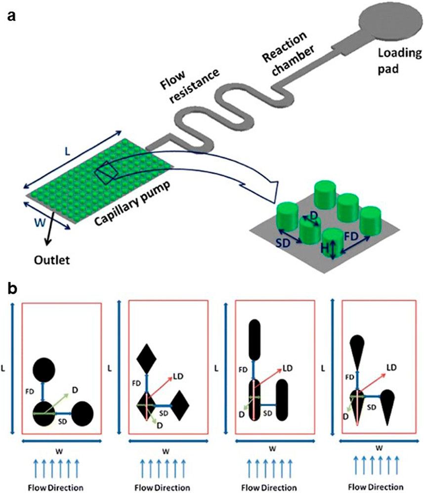
Figure 8. (A) Schematics of circular MIMP capillary pump in a microfluidic device. (B) The different pillar shapes (circle, diamond, elongated, pine) and geometrical parameters (D diameter, LD large diameter, SD side distance between pillars, FD forward distance between pillars) are investigated. Reproduced with permission from Madadi et al. (2014).
8 Capillary valves
Among different types of microvalves, capillary valves stand out due to their reliability and the fact that they do not require actuators, external power, or moving parts. They are widely used in microfluidic platforms, including Point-of-Care (POC) devices (Yoon et al., 2006; Khanjani et al., 2020; Barman et al., 2021; Wang et al., 2021).
8.1 Delay valves (DV)
As discussed in previous sections, delay valves manage the liquid front, reducing bubble entrapment and fluid bypass risks (Makhinia et al., 2023; Dos Ramos et al., 2016; Lai and Chung, 2018; Nie et al., 2020), especially in the connected CPs. This can be achieved by decreasing the capillary pressure in the intersection of two pumps. These valves slow down the meniscus progression in merging channels by increasing junctional channel size. A flow resistance at the end part minimizes the chance of fluid speeding in the channel and its bypass. In one study, authors designed a manufacturable DV, featuring several parallel comb-like protrusions and intermediate channels that facilitate precise control over timing (Li et al., 2017a).
8.2 Stop valves
Stop valves feature a restriction followed by an abrupt cross-sectional change, stopping fluid progression (Zimmermann et al., 2008; Barman et al., 2021; Azizian et al., 2023a; Papadimitriou et al., 2018; Glière and Delattre, 2006). A narrower width before the abrupt change and a larger angle deviation in the abrupted channel ensures a more reliable stop valve functionality. Ideally, the enlargement of the cross-section should occur in all directions, but it requires complicated fabrication processes. However, the stop valves with alterations in cross-section in the plane are not robust enough, with creeping possibilities from the bottom and above surfaces. To mitigate the creeping, the sealing can be made of less hydrophilic materials (e.g., PDMS) to prevent the valve’s break in the top surface. The hydrophobic nature of the cover can prevent the corner flow which breaks the valve. Increasing the aspect ratio of the valve stops the leakage from the bottom (i.e., depth/width>10), while it increases the complexities associated with the valve’s microfabrication process. In 2006, Glière and Delattre (2006), using a two-level deep reactive ion etching (DRIE) technology, generated a novel capillary stop valve design that extended the channel section in both width and depth. They determined that the liquid meniscus could be stopped at the valve opening in all situations. Additionally, the resultant burst pressure was high enough to enable accurate regulation and monitoring.
The following expression can be used to predict the behaviour of a stop valve, indicating that if the abrupt enlargement of the conduit curvature is set as β > α, when
Wherein, w is the width of the meniscus in the valve, α defines the half of the angle inscribed in the meniscus when its shape is approximated as an arc, θ indicates the contact angle of the meniscus with channel walls, β demonstrates the angle between new and old direction of the microchannel wall, and γla shows the liquid-air interface surface tension.
8.3 Trigger valves (TVs)
The combination of two stop valves, in which the sample in one of the valves triggers the other one in flow junctions (intersection) is called a trigger valve (Safavieh et al., 2015). The delay in the simultaneous arrival of two liquids might lead to bubble entrapment which can cause the blockage of channels, thus controlling the flow timing is necessary. Logical functions can be implemented in the system using TV as well. A liquid reaching the junction is stopped in the entrance due to the geometry of the valve until the other channel is filled with a second liquid, then the leakage between two valves triggers the liquids to progress into a common channel. The geometrical design of the valve can determine its functionality. The timing can be programmed for independent processes or for more than two fluids using a trigger valve to synchronize their movement. An n-to-1 AND (logical function) gate can be designed with the same concept. In 2004, Melin et al. (2004) found that the angle at which two valves meet each other and the spacing between them affects performance. The combination of a trigger valve with a long channel could be turned into an embedded timer within the capillary system. While the fluid was filling the meandered channel, the other filling front was stopped at the trigger valve junction until both streams meet and move forward. Two streams could be triggered with suction in the common outlet channel as well.
Conventional TVs are susceptible to leakage along the bottom or the top wall of the channel, similar to the stop valves. Safavieh proposed the design of a two-level trigger valve to increase the robustness of conventional ones (Figure 9A). A perpendicular flow within the wider channel triggers the fluid and breaks the stop valve. Two-level TV experience expansion both laterally and vertically at the bottom, while the top surface of the valve is covered with hydrophobic PDMS, minimizing the chance of creeping. They compared the proposed two-level TV with conventional ones and claimed that two-level TV with an aspect ratio of 1.5 would maintain the fluid for up to 20 min with no leakage in several experiments while the conventional TV with an aspect ratio of 3 experienced leakages within 2 s (Safavieh and Juncker, 2013).
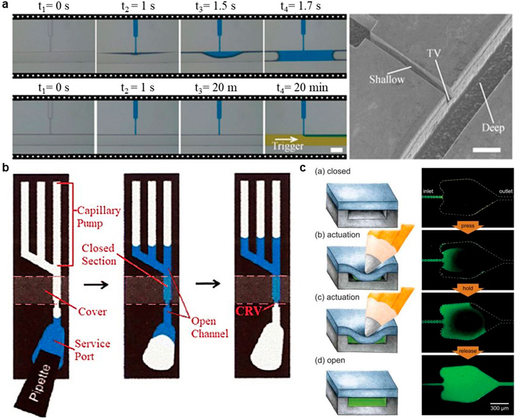
Figure 9. Capillary valves. (A) Two-level TV consisted of a shallow conduit intersecting a deep one and a hydrophobic coating. In the 3d detail the abrupt enlargement in the cross-section of the microchannel occurs in 2 directions: laterally and vertically. This three-dimensional geometry (aspect ratio, depth/width = 1.5) with the help of the hydrophobic coating increased the retention time of the valve up to 20 min. Reproduced with permission from Safavieh and Juncker (2013). (B) CRV: The CP of this device generates sufficient capillary pressure to drain both the service port and its attached access channel. The constriction (the CRV), located immediately upstream of the reaction chamber, is designed to be the smallest structure in the capillary system and therefore has the highest capillary pressure. The CRV pinches the interfacial meniscus of the wetting fluid and protects the reaction chamber from accidental drying. In this situation, subsequent solutions can be dispensed from the service port and drawn into the reaction chamber in the same way. Reproduced with permission from Juncker et al. (2002). (C) The authors introduced capillary soft valves (CSVs) as a simple method of controlling fluid flow in capillary-driven microfluidics. These valves function as normally closed units that can be activated by applying external pressure to their soft PDMS top layer. CSVs are designed to support complex assays requiring a wide range of operating temperatures and interactions with probes, dyes and species. They are also easy to integrate into circuits, design and operate. Reproduced with permission from Hitzbleck et al. (2012).
Combining trigger and stop valves, Li et al. presented a comb-like capillary time-valve to delay fluid in a predetermined manner for bioassays (Li et al., 2017a). The valve contained multiple comb-like protrusions. The filling front stopped temporarily at the edge of comb shape structures and started to progress along the edge until it reached the edge of the chip and triggered the fluid’s longitudinal flow, similar to the working principle of serpentine CP.
8.4 Capillary Retention Valves (CRV), Retention Burst Valves (RBV)
CRV and RBV work by reducing cross-sections to increase capillary pressure and preventing downstream drainage. CRVs hold the fluid permanently, while the RBVs act as release valves, and burst the flow at pressures higher than a predetermined threshold. Figure 9B shows a CRV integrated into the capillary system of Juncker et al., which prevented the access channel from drying out, thus inhibiting bubble formation or cross-contamination. The dimensions of constrained parts of CRV and RBV determines their strength to stop the fluid. If the pressure within the valve is higher than the pressure of CP, it would be a CRV, which will drive the fluid to the end. But if the pressure of CP is higher, the RBV will form, which will burst once the pressure in one point drops below the threshold of the valve. The hysteresis between the advancing and receding contact angles necessitates the dimension of CP to be much less than RBV, to ensure the valve’s drainage.
8.5 Capillary soft valves (CSVs)
Hitzbleck et al. introduced capillary soft valve (CSV) (Figure 9C), which halts the fluid flow by making an abrupt enlargement in its structure like a stop valve (Hitzbleck et al., 2012). The difference is that this normally closed valve is actuated with regular external pressure on its top layer, which can be simply made of PDMS, a soft enough material for this application. Gently pressing on the cover will increase the capillary pressure and opens the valve, causing wicking of the fluid forward consequently.
In addition to the main capillary-based microfluidic elements introduced above, some studies have introduced ancillary elements or considerations to improve capillary system functionality. As an example, Li et al. presented a wavelike buffer at the inlet port of a capillary-driven device to eliminate the effect of initial velocity and pressure and reduce the probability of bubble generation. The buffer reduces the flow disturbance by changing the longitudinal flow into a transversal one, which renders the injected fluid flow steadily to perform a more accurate test (Li et al., 2017b).
9 Avoiding backflow
Backflow is one of the challenging issues in passive microfluidic systems with multiple inlet ports. It originates from the Laplace pressure difference between liquids loaded directly to each inlet. The liquid with higher pressure pushes back the other one to its inlet, causing the fluid direction in the second channel to reverse (Xu et al., 2020).
The pressure drop may be the result of the difference between inlet size, liquid properties, or the volume of liquids drop-casted on each inlet. The phenomena can be a problem during immunoassays or other capillary-driven systems containing sequential fluid flow. To balance this pressure difference, Kim et al. (2005) inserted a contact channel (Figure 10A) (as a pressure balancer) between two inlets to diminish the pressure difference and inhibit the undesired merging of the flow streams. Zhai et al. (2018) added a capillary-driven pressure balancer (Figure 10B) composed of capillary valves to a vacuum-driven micromixing device, to prevent non-synchronized pumping, backflow, and flow crosstalk. Lee et al. investigated the effect of different elements of surface tension-driven networks on the strength of backflow (Xu et al., 2020). The build-in pressure of a liquid in an inlet can be calculated using the following formula (Equation 18):
Wherein, σ is the surface tension of the solution injected at the inlet, h demonstrates the height of the convex meniscus of the solution at the inlet, and r indicates the radius of the spherical cap of the liquid, which can be assumed to be equal to the radius of the inlet reservoir.
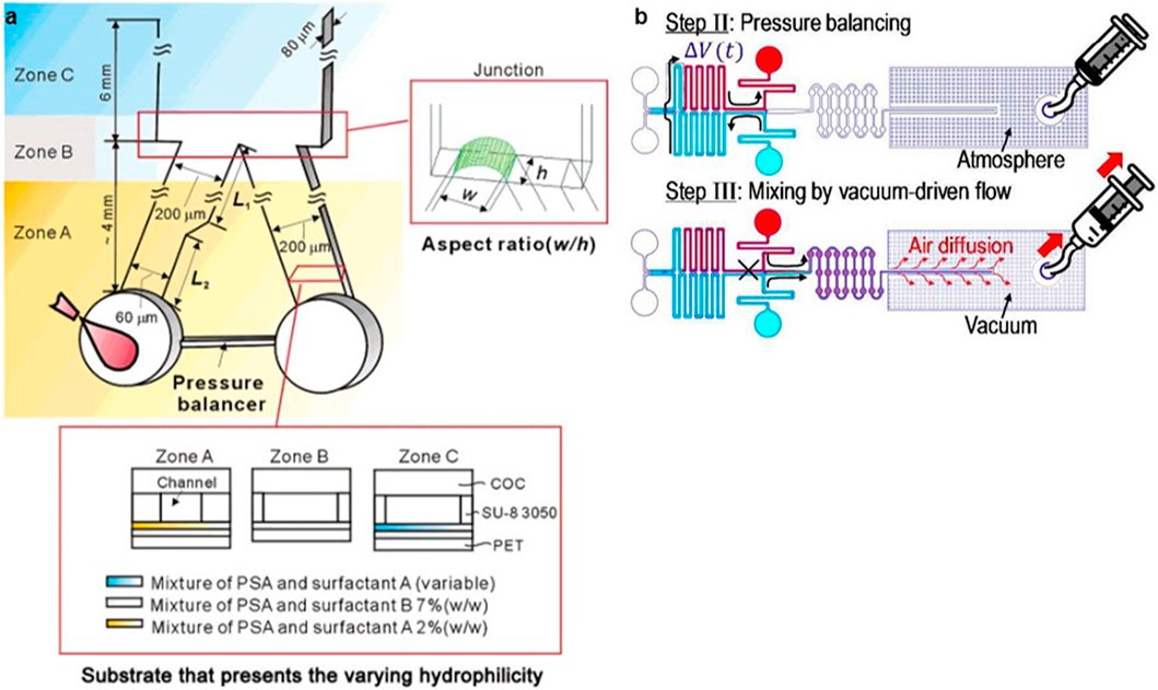
Figure 10. Preventing Backflow. (A) This solution consists of designing a pressure balancer bridge connecting two inlets, which allowed the combined streams to flow in a parallel laminar fashion. Authors conducted experiments showing that without the pressure balancer connection, there was re-entrant backflow at the junction. However, with the balancer configuration, the two merged streams flowed smoothly through the junction, maintaining a uniform parallel laminar flow (Kim et al., 2005). (B) In this work, a robust, portable micromixing device that is insensitive to backflow was designed, fabricated and characterised. The device is capable of handling both similar and dissimilar liquids. After loading the liquids at the inlets, the initial pressure difference caused by capillarity and gravity in each liquid at the two inlets is equalised by a capillary-driven pressure equalisation bypass. Finally, using manual syringe-assisted vacuum-driven pumping, the two pre-balanced liquid streams were allowed to enter a dead-end micromixing channel synchronously and without backflow. Reproduced with permission from Zhai et al. (2018).
In a separate study, Lee et al. argued that the variation in time constant ratios of the inlet channels in the capillary system is responsible for the occurrence of backflow phenomena (Lee et al., 2018). They found that the initial pressure difference at the inlets solely impacts the intensity of the backflow. Authors showed that backflow could be effectively prevented by employing inlet-channel elements that featured time constants (τk) that increased sequentially with each successive step.
In Equation 19, Ck is the fluidic conductance–the inverse of the fluidic resistance–of the k-th channel, rk is the radius of the k-th inlet, and σ is the surface tension of the injected solution.
10 Fabrication strategies of the devices
The fabrication techniques employed in the semiconductor industry are reducing the minimum feature size of microchannels to a mere few microns (Olanrewaju et al., 2018; Sun et al., 2021; Xie et al., 2024). These technologies are now ready for the mass production of high-quality components but require an extremely high up-front investment cost. Other less expensive fabrication techniques have been successfully developed and implemented in the production of functional microfluidic devices (Xie et al., 2024). These include CO₂ lasers, imprinting methods, molding, etching, lithographic fabrication, and various 3D printing methods, among others.
Laser technology typically exhibits a resolution in the range 15 µm (Yong et al., 2022; Sima and Sugioka, 2021; Zhang W. et al., 2022). Infrared radiation at a wavelength of 10.6 μm is frequently employed. It entails a sophisticated interaction of photothermal and photochemical processes. During the process of photon absorption, specific chemical bonds within the workpiece are ruptured directly, while others are broken because of the thermal energy released by the excited molecules. When the continuous CO₂ laser beam is focused on the workpiece, a rapid increase in temperature is observed. Consequently, the material melts and undergoes degradation, resulting in the formation of microchannels. In the case of femtosecond lasers, which are particularly useful to produce transparent capillary tubes featuring micro and nanopatterns on their internal surfaces, they typically operate at a wavelength of 1,030 nm (Yong et al., 2022; Clabel et al., 2023).
Molding represents a cost-effective methodology for the fabrication of functional microfluidic devices (Thuau et al., 2018). Molded components display a wide range of useful properties, including viscoelasticity, transparency, biocompatibility, durability, and biodegradability among others. The process, which resolution is approximately 100 μm, typically involves the organisation of a gel wire in an intended pattern on a layer of precured PDMS within a dish, which is then covered with another layer of PDMS that will undergo a curing process (Berthier et al., 2019; Lakhera et al., 2022). Subsequently, the original gel wires are removed using boiling water, after which a hydrophobic treatment is applied.
Imprinting techniques are an efficient method for fabricating microfluidic devices. These techniques achieve a resolution of approximately 20 nm and enhance production efficiency to over 100 samples per template (Xie et al., 2024; Luo et al., 2023). Moreover, these techniques exhibit remarkable reproducibility. The first generation of this technique involved pressing a thin wire into a heated softened plastic. The latest developments involve the use of silicon wafers to imprint a thermoplastic substrate (Azizipour et al., 2020).
Etching process, which offers a resolution of up to 5 μm (Ban et al., 2014; Li et al., 2019), is closely associated with lithography. This process consists of the removal of undesired materials from a silicon wafer through the application of either chemical or physical methods. Wet etching (chemical) is a process that relies on the use of solvents and solutions. The benefits of this method include good selectivity, excellent repeatability, high production efficiency, simplicity of equipment, and low costs. Its main drawbacks are the necessity for extensive drilling, and the generation of significant quantities of chemical waste among others. Dry etching techniques (light volatilisation, vapor-phase etching, plasma etching, metal etching, dielectric etching, and silicon etching, etc.) offer several advantages, including high repeatability, acceptable anisotropy, improved controllability, elevated selection ratios, flexibility, and also is more environmentally friendly (generating no chemical waste). However, dry etching is more expensive and requires complex equipment (high costs associated with cleanroom infrastructure and typically lengthy design-to-device timelines are due to the necessary photolithography masks and intricate fabrication processes) (Chanson et al., 2018).
Lithography is a technique employed to fabricate high-precision functional microfluidic devices, with typical resolutions reaching 20 μm (Lan et al., 2021; Carbonell et al., 2018). However, a significant disadvantage of lithography is that it necessitates the use of flat substrates and the maintenance of highly purified working environments (cleanrooms). The process commences with the deposition of a uniform layer of photoresist onto a silicon dioxide (SiO₂) wafer. Subsequently, a mask is employed to selectively expose and cure the photoresist, thereby creating a geometric pattern that mirrors the mask. The pattern is then developed in the photoresist, which serves to protect specific areas of the SiO₂ wafer during the subsequent etching process. Once the etching process is complete, the photoresist layer is removed, and an upper cladding layer is added to the patterned wafer.
Soft lithography represents a more straightforward and cost-effective alternative with similar resolutions to those of lithography (Gao et al., 2023; Zhang Y. et al., 2022). This method involves the creation of a negative of the channel designs through the formation of ridges in photoresist on a silicon wafer, which can then be utilised for the replication of the design in soft and transparent polydimethylsiloxane (PDMS). The generation of a single silicon wafer with positive patterns allows for the rapid production of multiple PDMS replicas in a laboratory setting. This process, which takes approximately 4 hours, employs common materials and an oven. When greater efficiency and larger-scale production are required, techniques such as hot embossing (which takes just a few minutes) and injection molding (which can be completed in mere seconds) can be utilized, albeit at a higher associated cost (Xie et al., 2024).
Finally, recent research (Makhinia et al., 2023; Azizian et al., 2023a; Cabrera-Moreta and Casals-Terré, 2024; Sochol et al., 2018) has highlighted 3D printing technology as a promising tool for manufacturing microdevices. Over the past few years, additive manufacturing has gained attention due to its speed, simplicity, and cost-effectiveness in the production of devices. We can find some 3D printing techniques that are currently being used for the fabrication of devices: Fused deposition modelling (FDM) is predominantly employed for the fabrication of microfluidic devices through moulding. Its resolution is approximately 100 μm, resulting in the production of parts with suboptimal surface quality (Duarte et al., 2024). Usually, a sacrificial mould for the microchannels is produced using a PVA (polyvinyl alcohol) filament. This is then positioned on a thin layer of cured polymer and covered with a fully degassed uncured polymer. Following ultrasonic cleaning and the removal of the printed PVA mould, a complete microchannel is achieved. Mult-jet modelling (MJM) technology can generate parts with a great variety of behaviours (hardness, flexibility, long-range elasticity, and a wide spectrum of colours). Its resolution is about 15 µm. However, these materials are costly and exclusive. The photopolymer is dispensed through a series of linearly arranged nozzles, operating either in continuous mode or drop-on-demand mode. It is then applied to the platform as microdroplets and cured using a uniform UV light source. Additionally, a water-soluble support structure is employed, which is completely removed upon completion of the printing process (Duarte et al., 2024; Aladese and Jeong, 2021). Digital Light Processing (DLP) has a resolution of up to 10 µm and functions by projecting images that have undergone digital processing. During the light curing procedure, ultraviolet light is directed onto the surface of photosensitive resin. Once the functional microfluidic devices have been printed, they are cleaned with isopropanol. Stereolithography (SLA) is quite comparable to DLP technology, achieving resolutions of around 25 μm. However, instead of projecting images, SLA employs a laser to cure each point of the model, maintaining high quality. Although it tends to be slower than DLP, SLA often delivers superior surface quality and richer details in most cases. Two-photon polymerisation (2PP). In contrast to single-photon polymerisation (SPP), which is employed in SLA, DLP, and MJM, 2PP utilises two photons for light curing. This process occurs under highly demanding conditions that require specific materials and exceptionally high energy densities. The dimensional accuracy of 2PP is 50 nm, and it is a very expensive process (Kotz et al., 2021; Carlotti and Mattoli, 2019).
11 Surface treatment methods
Inorganic materials such as silicon and glass were preferred for the fabrication of early microfluidic devices due to their availability and common hydrophilic properties (imposing a contact angle of 52° and 25°, respectively) (Nagy, 2019). However, silicon is fragile and expensive. Besides, its opaque nature limits its applications with optical detections. The amorphous structure of the glass makes it difficult for fabrication of high aspect ratio channels; thus, despite its low cost, the fabrication process can be expensive and time-consuming (Hou et al., 2017). Alternatively, organic materials are easy to use, enabling fast micro-channels prototyping. Based on their intrinsic properties, Hou et al. categorized organic-based materials for microfluidic fabrication into five classes: 1) elastomers (e.g., PDMS), 2) thermosets (like SU-8 and polyimide), 3) plastics (such as PMMA), PS, and Polytetrafluoroethylene (e.g., PTFE), 4) hydrogels, and 5) paper (Ren et al., 2013; Hou et al., 2017; Mou and Jiang, 2017).
Among emerging manufacturing strategies, additive manufacturing has garnered significant interest. However, despite the excitement from early adopters, its effectiveness is somewhat constrained by the technical challenge of producing reliable microfluidic channels with sizes smaller than one hundred micrometres (Azizian et al., 2023a; Cabrera-Moreta and Casals-Terré, 2024; Cabrera-Moreta et al., 2024). As a result, PDMS lithography remains the dominant fabrication method in laboratories. Introduced by Xia and Whitesides in 1998 (Xia and Whitesides, 1998), soft lithography using PDMS has become the most common approach for creating low-cost microfluidic prototypes (Niculescu et al., 2021; Zhang Y. et al., 2022).
The advantages of PDMS include transparency, which enables real-time monitoring of the process, biocompatibility, inert nature, scalability, and permeability, which all are important factors for long-term cell growth-contained applications (diffusion coefficient of ∼2,000–4,000 μm2/s for O2 and ∼1,000 μm2/s for CO2) (Aghajanloo et al., 2024). However, nonspecific protein adsorption and absorption of hydrophobic analytes (Qian et al., 2020) can lead to the fouling of the channels and inaccurate measurements. Indeed, its hydrophobic nature (WCA∼108°± 7°) can be considered as the main disadvantage of using PDMS as the substrate material in the case of capillary-based platforms. As discussed before, a hydrophobic surface repels water, thus it is difficult to introduce aqueous solutions into such surfaces. Therefore, surface treatment is critical in these systems to minimize molecular absorption and render the PDMS a hydrophilic surface. Besides, it can facilitate the process of bonding between the treated PDMS with its substrate, which may be PDMS, glass or other similarly modified surfaces to make a strong irreversible sealing. Table 3 provides an overview of commonly used microfluidic materials, highlighting their key characteristics.
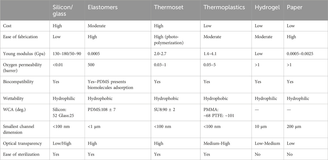
Table 3. Comparative guide to the most commonly used materials in the fabrication of microfluidic devices and their main characteristics. This synthesis has been created by cross-referencing the data obtained in the research of Ren et al. (2013), Mou and Jiang (2017), Niculescu et al. (2021).
Surface oxidation methods involve exposing PDMS to an energy source (e.g., plasma, UV light, and corona discharge) may change its surface characteristics. Plasma treatment using an ionized gas to functionalizing the surface is the most popular method of surface modification due to its simple and short process. Oxygen, nitrogen, argon, and hydrogen bromide are among the most commonly used materials in plasma treatment. The PDMS properties such as WCA, surface elasticity after plasma modification, and durability depends on the surface characterization, power, and duration of exposure to the plasma source. A prolonged process is reported to stiffen the PDMS surface, while it might lead to crack formation. UV/ozone light is another common method allowing for deep surface modification without material weakening. However, the UV process is much slower than the plasma method (Makamba et al., 2003).
Surface Oxidation methods can not last long; the process of hydrophobic recovery or aging return PDMS hydrophobic properties within 1 hour. Coating the PDMS surface by a sol-gel method, wet chemical methods, such as layer-by-layer deposition, non-ionic surfactants, and charged polymers are other common ways for PDMS surface functionalization (Zhou et al., 2010; Zhou et al., 2012).
Although these methods are rapid and straightforward, weak connections between surface and coating materials, due to the lack of covalent bonding has remained a challenging issue. Better results can be achieved through chemical modification methods, including chemical vapor deposition, self-assembled monolayers, silanization, and polymer brushes from grafting to and grafting from methods (Gökaltun et al., 2019). More comprehensive reviews about these modification methods, their implementation details, and results, which are beyond the scope of this article, can be found in the literature (Lu et al., 2020; Gao et al., 2023; Makamba et al., 2003; Tu et al., 2012; Almutairi et al., 2012; Akther et al., 2020; Madadi and Casals-Terré, 2013).
12 Numerical models applied to capillary-driven devices
Although the geometrical design parameters of a capillary system- such as dimensions, curvatures, and pinning sites- are of great importance due to the risk of bubble entrapment and the need to prevent it, the numerical analysis of capillary flow behaviour remains underexplored. This probably stems from the complexities related to the wetting phenomena physics and the geometries of such systems. CFD tools and their associated numerical modelling play an essential role in advancing our understanding of microfluidics and capillary flow. Among a few available reports, Clime et al. developed a 3D numerical optimization model for the capillary-based delivery of the liquid from a hydrophilic channel to a reservoir to investigate the potential bubble entrapment or flow blockage. The dynamic of capillary flow is modeled based on the Lattice Boltzmann algorithm. They studied the fluid’s advancement into the channel for different values of contact angle, the curvature of the lateral edges, and the geometry of the reservoir (Clime et al., 2012), which are the key parameters in the geometry of a capillary device. In this regard, another computational flow simulation has done on 2D non-uniform capillary-driven micro- channels, which are common in capillary valve design. Erickson et al. (2002) investigated converging-diverging and diverging-converging capillary shapes with different dimensions and ratios as well as the effect of contact angle and wetting properties on the fluid’s progression. Another study performed by Lai et al. on zig-zag channels to work as resistance elements or mixers. They investigated capillary-driven meandered channels with different geometrical ratios through 2D numerical simulation–neglecting the channel depth- to investigate the effect of channel width on the resistance, speed, and pressure drop of a capillary-driven flow (Lai and Chung, 2013). This study provides valuable insights for designing meander channels in capillary systems.
As discussed, microarray structures are the most desirable design for CPs. Azizian et al. (2023b) developed a novel capillary valve known as the π-valve that operates without diffusion. The system was modelled numerically using the Navier‒Stokes equations, which included surface tension forces, and an adaptive spatial discretization was employed to track the liquid–air interfaces. This valve (Figure 11A) incorporates a three-dimensional design with a void space serving as a buffer between two fluids, ensuring they do not directly mix. Upon activation, pneumatic suction from the downstream capillary flow displaces the air trapped in the void, effectively preventing any gas bubbles from entering the system. This design successfully avoids diffusive mixing prior to valve activation. The researchers employed numerical simulations to evaluate the valve’s functionality and to optimize its dimensions and used 3D printing to create the mold or microfluidic chip. This cutting-edge valve can provide notable advantages, especially in minimizing cross-contamination.
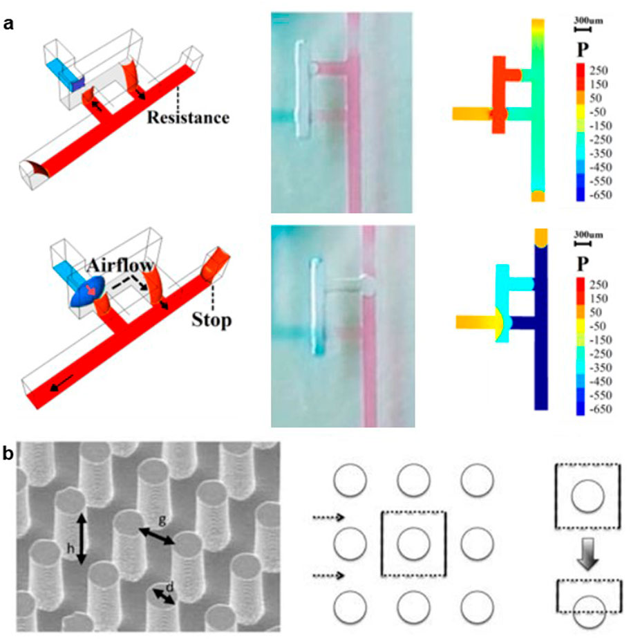
Figure 11. (A) Simulation and assay of the novel π-valve. In the computational fluid dynamics simulation images, the phase contour between the air and liquid phases and the pressure values can be observed. The capillary-driven flow through a microfluidic device was modelled as an incompressible multiphase flow with an immiscible liquid–air interface. The governing equations were solved using the Gerris open-source computational fluid dynamics (CFD) code, which employed the adaptive mesh refinement (AMR) technique and semi-structured quad/octree spatial cells (Azizian et al., 2023b). Copyright 2023 the authors. Published by Springer Nature under a Creative Commons Attribution (CC BY) license. (B) In another study a predictive model for pressure-driven viscous flow through posts was developed using finite element simulations. This viscous scaling model accounted for viscous drag from both the post surface and the supporting substrate and was found to be effective for a wide range of post geometries. The model was then combined with a surface energy-based method to estimate capillary pressure, resulting in a comprehensive scaling law similar to Washburn dynamics. Reproduced with permission from Srivastava et al. (2010).
Srivastava et al. (2010) presented a finite element analysis scaling model to predict the viscous flow within a micro post array across various geometries (Figure 11B). They demonstrated that the flow rate between two adjacent pillars in an array scale as h1.17 g1.33 d−0.5, where h shows the post height, d demonstrates the post diameter and g indicates the gap size between the posts. They extended the model for investigating the wetting rate of posts with different combinations of h, g, and d. The results might be helpful from the fabrication viewpoint to optimize the designed dimensions with the microfabrication facilities. Experimental validation for the model was presented as well.
In a related work (Madadi et al., 2014), the authors employed numerical analysis as a fundamental method for calculating the flow resistance encountered in microchannel-integrated micropillars (MIMPs). This innovative approach allowed for a comprehensive investigation of fluid dynamics within these structures by solving the flow characteristics numerically for a variety of pillar shapes and arrangements. The numerical simulations provided valuable insights into how the design of the micropillars impacts flow characteristics. Their findings revealed that the configuration leading to the highest flow resistance involved the use of elongated pillars. In contrast, the study identified that pillar shapes resembling pine and diamond demonstrated significantly lower flow resistance values, highlighting the importance of geometric design in optimizing fluid flow.
13 Conclusion
In conclusion, capillary-driven microfluidic systems offer significant advantages in various applications, particularly in point-of-care (POC) diagnostics and biological assays, due to their simplicity, cost-effectiveness, and ability to function without complex external equipment. These systems leverage the interaction between fluid surface tension, geometry, and substrate wettability, making capillary-driven pumps highly effective for fluid flow control in microchannels. While challenges such as fluid flow control, evaporation, and reproducibility persist, innovations in design—such as optimizing CPs, developing open-channel configurations, and integrating porous materials—have improved the reliability and performance of these systems. Hybrid approaches that combine solid and porous materials, alongside the integration of passive and active pumping methods, further enhance the versatility of capillary microfluidics. As research continues to advance in this field, capillary-driven devices are poised to play a transformative role in healthcare and diagnostic technologies, providing rapid, sensitive, and efficient solutions for a wide range of applications.
Author contributions
EK: Writing–original draft. AF: Writing–original draft, Writing–review and editing. JL: Investigation, Writing–original draft, Writing–review and editing. SN: Validation, Visualization, Writing–review and editing. JC: Resources, Writing–review and editing. SM: Resources, Validation, Writing–review and editing. BA: Conceptualization, Investigation, Validation, Writing–review and editing.
Funding
The author(s) declare that no financial support was received for the research, authorship, and/or publication of this article.
Conflict of interest
The authors declare that the research was conducted in the absence of any commercial or financial relationships that could be construed as a potential conflict of interest.
Generative AI statement
The author(s) declare that no Generative AI was used in the creation of this manuscript.
Publisher’s note
All claims expressed in this article are solely those of the authors and do not necessarily represent those of their affiliated organizations, or those of the publisher, the editors and the reviewers. Any product that may be evaluated in this article, or claim that may be made by its manufacturer, is not guaranteed or endorsed by the publisher.
References
Aghajanloo, B., Ejeian, F., Frascella, F., Marasso, S. L., Cocuzza, M., Tehrani, A. F., et al. (2023). Pumpless deterministic lateral displacement separation using a paper capillary wick. Lab. Chip 23, 2106–2112. doi:10.1039/d3lc00039g
Aghajanloo, B., Inglis, D. W., Ejeian, F., Tehrani, A. F., Esfahani, M. H. N., Saghafian, M., et al. (2022). Effect of process parameters on separation efficiency in a deterministic lateral displacement device. J. Chromatogr. A 1678, 463295. doi:10.1016/j.chroma.2022.463295
Aghajanloo, B., Losereewanich, W., Pastras, C. J., and Inglis, D. W. (2024). Wicking pumps for microfluidics. Biomicrofluidics 18, 061501. doi:10.1063/5.0218030
Agustini, D., Caetano, F. R., Quero, R. F., Fracassi da Silva, J. A., Bergamini, M. F., Marcolino-Junior, L. H., et al. (2021). Microfluidic devices based on textile threads for analytical applications: state of the art and prospects. Anal. Methods 13, 4830–4857. doi:10.1039/d1ay01337h
Akbari, Z., Raoufi, M. A., Mirjalali, S., and Aghajanloo, B. (2023). A review on inertial microfluidic fabrication methods. Biomicrofluidics 17, 051504. doi:10.1063/5.0163970
Akther, F., Yakob, S. B., Nguyen, N.-T., and Ta, H. T. (2020). Surface modification techniques for endothelial cell seeding in PDMS microfluidic devices. Biosens. (Basel) 10, 182. doi:10.3390/bios10110182
Akyazi, T., Tudor, A., Diamond, D., Basabe-Desmonts, L., Florea, L., and Benito-Lopez, F. (2018). Driving flows in microfluidic paper-based analytical devices with a cholinium based poly(ionic liquid) hydrogel. Sensors Actuators B Chem. 261, 372–378. doi:10.1016/j.snb.2018.01.154
Aladese, A. D., and Jeong, H.-H. (2021). Recent developments in 3D printing of droplet-based microfluidics. Biochip J. 15, 313–333. doi:10.1007/s13206-021-00032-1
Almutairi, Z., Ren, C. L., and Simon, L. (2012). Evaluation of polydimethylsiloxane (PDMS) surface modification approaches for microfluidic applications. Colloids Surfaces A Physicochem. Eng. Aspects 415, 406–412. doi:10.1016/j.colsurfa.2012.10.008
Armbruster, M. R., Grady, S. F., Arnatt, C. K., and Edwards, J. L. (2022). Isobaric 4-plex tagging for absolute quantitation of biological acids in diabetic urine using capillary LC-MS/MS. ACS Meas. Sci. au 2, 287–295. doi:10.1021/acsmeasuresciau.1c00061
Azizian, P., Casals-Terré, J., Ricart, J., and Cabot, J. M. (2023b). Diffusion-free valve for preprogrammed immunoassay with capillary microfluidics. Microsyst. Nanoeng. 9, 91. doi:10.1038/s41378-023-00568-2
Azizian, P., Casals-Terré, J., Ricart, J., Cabot, M., and Capillary-Driven Microfluidics, J. (2023a). Capillary-driven microfluidics: impacts of 3D manufacturing on bioanalytical devices. Analyst 148, 2657–2675. doi:10.1039/D3AN00115F
Azizipour, N., Avazpour, R., Rosenzweig, D. H., Sawan, M., and Ajji, A. (2020). Evolution of biochip technology: a review from lab-on-a-chip to organ-on-a-chip. Micromachines (Basel) 11, 599. doi:10.3390/mi11060599
Ban, C., Park, J., Jang, D. Y., and Han, A. (2014). Liquid-phase capillary etching of poly(dimethylsiloxane) microchannels with tetra-n-butylammonium fluoride. J. microelectromechanical Syst. 23, 276–283. doi:10.1109/JMEMS.2014.2301040
Barman, U., Lagae, L., and Jones, B. (2021). Capillary stop valve actuation by thermo-pneumatic- pressure for lab-on-chip systems. Microsyst. Technol. 27, 681–692. doi:10.1007/s00542-020-05026-x
Berry, S. B., Lee, J. J., Berthier, J., Berthier, E., and Theberge, A. B. (2019). Droplet incubation and splitting in open microfluidic channels. Anal. methods 11, 4528–4536. doi:10.1039/c9ay00758j
Berthier, E., and Beebe, D. J. (2007). Flow rate analysis of a surface tension driven passive micropump. Lab. Chip 7, 1475–1478. doi:10.1039/b707637a
Berthier, E., Dostie, A. M., Lee, U. N., Berthier, J., and Theberge, A. B. (2019). Open microfluidic capillary systems. Anal. Chem. 91, 8739–8750. doi:10.1021/acs.analchem.9b01429
Berthier, J., Brakke, K. A., Furlani, E. P., Karampelas, I. H., Poher, V., Gosselin, D., et al. (2015). Whole blood spontaneous capillary flow in narrow V-groove microchannels. Sensors Actuators B Chem. 206, 258–267. doi:10.1016/j.snb.2014.09.040
Bracke, M., Voeght, F., and Joos, P. (1989). The kinetics of wetting: the dynamic contact angle. Prog. Colloid and Polym. Sci., 142–149. doi:10.1007/BFb0116200
Bruus, H. (2008). Theoretical microfluidics. Oxford: Oxford University Press. doi:10.1093/oso/9780199235087.001.0001
Cabrera-Moreta, V. H., and Casals-Terré, J. (2024). Capillary-driven microdevice mixer using additive manufacturing (SLA technology). Appl. Sci. 14, 4293. doi:10.3390/app14104293
Cabrera-Moreta, V. H., Casals-Terré, J., and Salguero, E. (2024). Validation of fluid flow speed behavior in capillary microchannels using additive manufacturing (SLA technology). Processes 12, 1066. doi:10.3390/pr12061066
Carbonell, C., Valles, D. J., Wong, A. M., Tsui, M. W., Niang, M., and Braunschweig, A. B. (2018). Massively multiplexed tip-based photochemical lithography under continuous capillary flow. Chem 4, 857–867. doi:10.1016/j.chempr.2018.01.020
Carlotti, M., and Mattoli, V. (2019). Functional materials for two-photon polymerization in microfabrication. Small 15, e1902687–n/a. doi:10.1002/smll.201902687
Casals-Terré, J., Farré-Lladós, J., López, J. A., Vidal, T., and Roncero, M. B. (2020). Enhanced fully cellulose based forward and reverse blood typing assay. J. Biomed. Mater. Res. Part B Appl. Biomater. 108, 439–450. doi:10.1002/jbm.b.34400
Chanson, R., Zhang, L., Naumov, S., Mankelevich, Yu.A., Tillocher, T., Lefaucheux, P., et al. (2018). Damage-free plasma etching of porous organo-silicate low-k using micro-capillary condensation above −50°C. Sci. Rep. 8, 1886–1912. doi:10.1038/s41598-018-20099-5
Chen, H., Cogswell, J., Anagnostopoulos, C., and Faghri, M. (2012). A fluidic diode, valves, and a sequential-loading circuit fabricated on layered paper. Lab. Chip 12, 2909–2913. doi:10.1039/c2lc20970e
Chen, K., Amontree, J., Varillas, J., Zhang, J., George, T. J., and Fan, Z. H. (2020). Incorporation of lateral microfiltration with immunoaffinity for enhancing the capture efficiency of rare cells. Sci. Rep. 10, 14210. doi:10.1038/s41598-020-71041-7
Chuang, C. H., and Chiang, Y. Y. (2019). Bio-O-Pump: a novel portable microfluidic device driven by osmotic pressure. Sensors Actuators B Chem. 284, 736–743. doi:10.1016/j.snb.2019.01.020
Clabel, H. J. L., Paula, K. T., Pereira-da-Silva, M. A., Vollet-Filho, J. D., Marega, J. E., and Mendonça, C. R. (2023). Fabrication of micro patterns on BaTiO3:Er3+/Yb3+ perovskite films by femtosecond laser micromachining. Appl. Surf. Sci. 634, 157658. doi:10.1016/j.apsusc.2023.157658
Clime, L., Brassard, D., Pezacki, J. P., and Veres, T. (2012). Self-priming of liquids in capillary autonomous microfluidic systems. Microfluid. Nanofluidics 12, 371–382. doi:10.1007/s10404-011-0881-7
Dai, B., Li, K., Shi, L., Wan, X., Liu, X., Zhang, F., et al. (2019). Bioinspired janus textile with conical micropores for human body moisture and thermal management. Adv. Mater. 31, e1904113-n/a. doi:10.1002/adma.201904113
Desaegher, A., Marin, V., Beauvieux, M.-C., Colombiès, B., Lauga, M., Alloug, S., et al. (2025). Exploring strategies to rapidly identify false positives in high-sensitivity cardiac troponin I assay: a prospective study. Clin. Chim. Acta 565, 119996. doi:10.1016/j.cca.2024.119996
Dos Ramos, L., Lajoinie, G., Kieviet, B. D., de Beer, S., Versluis, M., Hempenius, M. A., et al. (2016). Redox control of capillary filling speed in poly(ferrocenylsilane)-modified microfluidic channels for switchable delay valves. Eur. Polym. J. 83, 507–516. doi:10.1016/j.eurpolymj.2016.06.002
Duarte, L. C., Figueredo, F., Chagas, C. L. S., Cortón, E., and Coltro, W. K. T. (2024). A review of the recent achievements and future trends on 3D printed microfluidic devices for bioanalytical applications. Anal. Chim. Acta 1299, 342429. doi:10.1016/j.aca.2024.342429
Epifania, R., Soares, R. R. G., Pinto, I. F., Chu, V., and Conde, J. P. (2018). Capillary-driven microfluidic device with integrated nanoporous microbeads for ultrarapid biosensing assays. Sensors Actuators B Chem. 265, 452–458. doi:10.1016/j.snb.2018.03.051
Erickson, D., Li, D., and Park, C. B. (2002). Numerical simulations of capillary-driven flows in nonuniform cross-sectional capillaries. J. Colloid Interface Sci. 250, 422–430. doi:10.1006/jcis.2002.8361
Fichera, A., Pagano, A., and Volpe, R. (2024). Microscale damper prototype: a preliminary study on suppressing air flow oscillations within microchannels. J. Phys. Conf. Ser. 2685, 012022. doi:10.1088/1742-6596/2685/1/012022
Fu, E., and Downs, C. (2017). Progress in the development and integration of fluid flow control tools in paper microfluidics. Lab. Chip 17, 614–628. doi:10.1039/c6lc01451h
Gao, S., Zhan, T., Zhou, W., Niu, F., Min, S., Xiao, A., et al. (2023). Mold embossing-based soft lithography for fabrication of complex non-rectangular channels. ACS Appl. Mater Interfaces 15, 31755–31764. doi:10.1021/acsami.3c01306
Gervais, L., and Delamarche, E. (2009). Toward one-step point-of-care immunodiagnostics using capillary-driven microfluidics and PDMS substrates. Lab. Chip 9, 3330–3337. doi:10.1039/b906523g
Gervais, L., and Delamarche, E. (2010). “Extended dynamic range capillary-driven microfluidics,” in Proceedings of the 14th International Conference on Miniaturized Systems for Chemistry and Life Sciences; International Conference on Miniaturized Systems for Chemistry and Life Sciences, Groningen: The Netherlands, October 3 2010, 809–811.
Gervais, L., Hitzbleck, M., and Delamarche, E. (2011). Capillary-driven multiparametric microfluidic chips for one-step immunoassays. Biosens. Bioelectron. 27, 64–70. doi:10.1016/j.bios.2011.06.016
Ghosh, S., Aggarwal, K., and Ahn, C. H. A new mobile healthcare system using smartphone and lab-on-a-chip for on-site diagnostics of malaria. (2017).
Ghosh, S., Aggarwal, K., Vinitha, T. U., Nguyen, T., Han, J., and Ahn, C. H. (2020). A new microchannel capillary flow assay (MCFA) platform with lyophilized chemiluminescence reagents for a smartphone-based POCT detecting malaria. Microsyst. Nanoeng. 6, 5. doi:10.1038/s41378-019-0108-8
Glière, A., and Delattre, C. (2006). Modeling and fabrication of capillary stop valves for planar microfluidic systems. Sensors Actuators A Phys. 130–131, 601–608. doi:10.1016/j.sna.2005.12.011
G Navascues Liquid Surfaces (1979). Theory of surface tension. Rep. Prog. Phys. 42, 1131. doi:10.1088/0034-4885/42/7/002
Gökaltun, A., Kang, Y. B. A., Yarmush, M. L., Usta, O. B., and Asatekin, A. (2019). Simple surface modification of poly(dimethylsiloxane) via surface segregating smart polymers for biomicrofluidics. Sci. Rep. 9, 7377. doi:10.1038/s41598-019-43625-5
Guijt, R. M., and Manz, A. (2018). Miniaturised total chemical-analysis systems (ΜTAS) that periodically convert chemical into electronic information. Sensors Actuators B Chem. 273, 1334–1345. doi:10.1016/j.snb.2018.06.054
Guo, W., Hansson, J., and Van Der Wijngaart, W. (2016). Capillary pumping independent of liquid sample viscosity. Langmuir 32, 12650–12655. doi:10.1021/acs.langmuir.6b03488
Guo, W., Hansson, J., and Wijngaart, W. (2018). van der Capillary Pumping Independent of the Liquid Surface Energy and Viscosity. Microsyst. Nanoeng. 4, 1–7. doi:10.1038/s41378-018-0002-9
Hemmig, E., Temiz, Y., Gökçe, O., Lovchik, R. D., and Delamarche, E. (2020). Transposing lateral flow immunoassays to capillary-driven microfluidics using self-coalescence modules and capillary-assembled receptor carriers. Anal. Chem. 92, 940–946. doi:10.1021/acs.analchem.9b03792
Hitzbleck, M., Avrain, L., Smekens, V., Lovchik, R. D., Mertens, P., and Delamarche, E. (2012). Capillary soft valves for microfluidics. Lab. Chip 12, 1972. doi:10.1039/c2lc00015f
Hou, X., Zhang, Y. S., Santiago, G. T., Alvarez, M. M., Ribas, J., Jonas, S. J., et al. (2017). Interplay between materials and microfluidics. Nat. Rev. Mater 2, 17016. doi:10.1038/natrevmats.2017.16
Jarrett, H., Wade, M., Kraai, J., Rorrer, G. L., Wang, A. X., and Tan, H. (2020). Self-Powered microfluidic pump using evaporation from diatom biosilica thin films. Microfluid. Nanofluidics 24, 36. doi:10.1007/s10404-020-02343-5
Jarujamrus, P., Prakobkij, A., Puchum, S., Chaisamdaeng, S., Meelapsom, R., Anutrasakda, W., et al. (2020). Acid-base titration using a microfluidic thread-based analytical device (ΜTAD). Anal. Lond. 145, 4457–4466. doi:10.1039/d0an00522c
Juncker, D., Schmid, H., Drechsler, U., Wolf, H., Wolf, M., Michel, B., et al. (2002). Autonomous microfluidic capillary system. Anal. Chem. 74, 6139–6144. doi:10.1021/ac0261449
Jurin, J. I. I. (1719). An account of some experiments shown before the royal society; with an enquiry into the cause of the ascent and suspension of water in capillary tubes. Philos. Trans. (R. Soc. (Great Britain) 1683) 30, 739–747. doi:10.1098/rstl.1717.0026
Karimi, S., Mojaddam, M., Majidi, S., Mehrdel, P., Farré-Lladós, J., and Casals-Terré, J. (2021). Numerical and experimental analysis of a high-throughput blood plasma separator for point-of-care applications. Anal. Bioanal. Chem. 413, 2867–2878. doi:10.1007/s00216-021-03190-1
Khanjani, E., Kargar-Estahbanaty, A., Taheri, A., and Baghani, M. (2020). Analysis of temperature-sensitive hydrogel microvalves in a T-junction flow sorter using full scale fluid–structure interaction. J. Intelligent Material Syst. Struct. 31, 1371–1382. doi:10.1177/1045389X20922914
Khodayari Bavil, A., and Kim, J. A. (2018). A capillary flow-driven microfluidic system for microparticle-labeled immunoassays. Analyst 143, 3335–3342. doi:10.1039/c8an00898a
Kim, K.-H., Lee, J., Kim, C.-H., and Kim, J.-H. (2021). Particle-based dynamic water drops with high surface tension in real time. Symmetry (Basel) 13, 1265. doi:10.3390/sym13071265
Kim, S.-J., Lim, Y. T., Yang, H., Shin, Y. B., Kim, K., Lee, D.-S., et al. (2005). Passive microfluidic control of two merging streams by capillarity and relative flow resistance. Anal. Chem. 77, 6494–6499. doi:10.1021/ac0504417
Koczula, K. M., and Gallotta, A. (2016). Lateral flow assays. Essays Biochem. 60, 111–120. doi:10.1042/EBC20150012
Kotz, F., Quick, A. S., Risch, P., Martin, T., Hoose, T., Thiel, M., et al. (2021). Two-photon polymerization: two-photon polymerization of nanocomposites for the fabrication of transparent fused silica glass microstructures (adv. Mater. 9/2021). Adv. Mater. 33. doi:10.1002/adma.202170062
Kumari, S., Samara, M., Ampadi Ramachandran, R., Gosh, S., George, H., Wang, R., et al. (2023). A review on saliva-based health diagnostics: biomarker selection and future directions. Biomed. Mater. and Devices 2, 121–138. doi:10.1007/s44174-023-00090-z
Lai, C. C., and Chung, C. K. (2013). Numerical simulation of the capillary flow in the meander microchannel. Microsyst. Technol. 19, 379–386. doi:10.1007/s00542-012-1629-3
Lai, C.-C., and Chung, C.-K. (2018). Facile design and fabrication of capillary valve for mixing using two-step PDMS moulding. Micro and Nano Lett. 13, 1408–1411. doi:10.1049/mnl.2018.5067
Lakhera, P., Chaudhary, V., Bhardwaj, B., Kumar, P., and Kumar, S. (2022). Development and recent advancement in microfluidics for point of care biosensor applications: a review. Biosens. Bioelectron. X 11, 100218. doi:10.1016/j.biosx.2022.100218
Lan, D., Shang, Y., Su, H., Liang, M., Liu, Y., Li, H., et al. (2021). Facile fabrication of hollow hydrogel microfiber via 3D printing-assisted microfluidics and its application as a biomimetic blood capillary. ACS Biomater. Sci. Eng. 7, 4971–4981. doi:10.1021/acsbiomaterials.1c00980
Lee, J. J., Berthier, J., Kearney, K. E., Berthier, E., and Theberge, A. B. (2020). Open-Channel capillary trees and capillary pumping. Langmuir 36, 12795–12803. doi:10.1021/acs.langmuir.0c01360
Lee, Y., Choi, M., and Kim, S. J. (2018). Method to prevent backflow in a capillarity network for bioassays: exploiting time constant ratios. Sensors Actuators B Chem. 255, 3630–3635. doi:10.1016/J.SNB.2017.09.093
Lei, K. F. (2018). Introduction: the origin, current status, and future of microfluidics. Microfluid. Fundam. Devices Appl., 1–18. doi:10.1002/9783527800643.CH1
Li, J., Liang, C., Wang, S., Guo, L., Liu, Z., and Liu, C. (2017b). A wavelike buffer for introducing samples into autonomous capillary microfluidic devices. J. Micromech. Microeng. 27, 017003. doi:10.1088/1361-6439/27/1/017003
Li, J., Liang, C., Zhang, B., and Liu, C. (2017a). A comblike time-valve used in capillary-driven microfluidic devices. Microelectron. Eng. 173, 48–53. doi:10.1016/j.mee.2017.03.013
Li, Y., Sun, K., Shao, Y., Wang, C., Xue, F., Chu, C., et al. (2025). Next-generation approaches for biomedical materials evaluation: microfluidics and organ-on-a-chip technologies. Adv. Healthc. Mater. 14, e2402611. doi:10.1002/adhm.202402611
Li, Y., Zhang, H., Yang, R., Tazrin, F., Zhu, C., Kaddoura, M., et al. (2019). In-plane silicon microneedles with open capillary microfluidic networks by deep reactive ion etching and sacrificial layer based sharpening. Sensors Actuators A Phys. 292, 149–157. doi:10.1016/j.sna.2019.04.008
Lillehoj, P. B., Wei, F., and Ho, C.-M. (2010a). A self-pumping lab-on-a-chip for rapid detection of botulinum toxin. Lab. Chip 10, 2265–2270. doi:10.1039/c004885b
Lillehoj, P. B., Wei, F., and Ho, C. M. (2010b). A self-pumping lab-on-a-chip for rapid detection of botulinum toxin. Lab. Chip 10, 2265–2270. doi:10.1039/c004885b
Lin, Q., Wu, J., Fang, X., and Kong, J. (2020). Washing-free centrifugal microchip fluorescence immunoassay for rapid and point-of-care detection of protein. Anal. Chim. Acta 1118, 18–25. doi:10.1016/j.aca.2020.04.031
Liu, H., Gao, S.-W., Cai, J.-S., He, C.-L., Mao, J.-J., Zhu, T.-X., et al. (2016). Recent progress in fabrication and applications of superhydrophobic coating on cellulose-based substrates. Materials 9, 124. doi:10.3390/ma9030124
Liu, Y., Gao, R., Zhuo, Y., Wang, Y., Jia, H., Chen, X., et al. (2023). Rapid simultaneous SERS detection of dual myocardial biomarkers on single-track finger-pump microfluidic chip. Anal. Chim. Acta 1239, 340673. doi:10.1016/j.aca.2022.340673
Liu, Y., and Li, G. (2018). A power-free, parallel loading microfluidic reactor array for biochemical screening. Sci. Rep. 8, 13664. doi:10.1038/s41598-018-31720-y
Liu, Y., Sun, L., Zhang, H., Shang, L., and Zhao, Y. (2021). Microfluidics for drug development: from synthesis to evaluation. Chem. Rev. 121, 7468–7529. doi:10.1021/acs.chemrev.0c01289
Lu, S., Zhao, Y., Hu, X., Lin, Y., and Ke, Y. (2020). Biomimetic fabrication of micron/nano-meter assembled superhydrophobic polymer fiber fabrics for oil/water separation. Mater. Lett. 262, 127152. doi:10.1016/j.matlet.2019.127152
Luo, X., Yang, L., and Cui, Y. (2023). Micropumps: mechanisms, fabrication, and biomedical applications. Sensors Actuators A Phys. 363, 114732. doi:10.1016/j.sna.2023.114732
Ma, J., Wang, Y., and Liu, J. (2017). Biomaterials meet microfluidics: from synthesis technologies to biological applications. Micromachines (Basel) 8, 255. doi:10.3390/mi8080255
Madadi, H., and Casals-Terré, J. (2013). Long-term behavior of nonionic surfactant-added PDMS for self-driven microchips. Microsyst. Technol. 19, 143–150. doi:10.1007/s00542-012-1641-7
Madadi, H., Casals-terré, J., Castilla-lópez, R., and Sureda-anfres, M. (2014). High-throughput microcapillary pump with efficient integrated low aspect ratio micropillars. Microfluid. Nanofluidics 17, 115–130. doi:10.1007/s10404-013-1295-5
Makamba, H., Kim, J. H., Lim, K., Park, N., and Hahn, J. H. (2003). Surface modification of poly(dimethylsiloxane) microchannels. Electrophoresis 24, 3607–3619. doi:10.1002/elps.200305627
Makhinia, A., Azizian, P., Beni, V., Casals-Terré, J., Cabot, J. M., and Andersson Ersman, P. (2023). On-demand inkjet printed hydrophilic coatings for flow control in 3D-printed microfluidic devices embedded with organic electrochemical transistors. Adv. Mater. Technol. 8. doi:10.1002/admt.202300127
Maki, A. J., Hemmila, S., Hirvonen, J., Girish, N. N., Kreutzer, J., Hyttinen, J., et al. (2015). Modeling and experimental characterization of pressure drop in gravity-driven microfluidic systems. J. Fluids Eng. 137. doi:10.1115/1.4028501
Mehrdel, P., Khosravi, H., Karimi, S., Martínez, J. A. L., and Casals-Terré, J. (2021). Flow control in porous media: from numerical analysis to quantitative μpad for ionic strength measurements. Sensors 21, 3328. doi:10.3390/s21103328
Melin, J., Roxhed, N., Gimenez, G., Griss, P., Vanderwijngaart, W., and Stemme, G. (2004). A liquid-triggered liquid microvalve for on-chip flow control. Sensors Actuators B Chem. 100, 463–468. doi:10.1016/j.snb.2004.03.010
Mohammed, M. I., and Desmulliez, M. P. Y. (2014a). Characterization and theoretical analysis of rapidly prototyped capillary action autonomous microfluidic systems. J. Microelectromechanical Syst. 23, 1408–1416. doi:10.1109/JMEMS.2014.2314470
Mohammed, M. I., and Desmulliez, M. P. Y. (2014b). Autonomous capillary microfluidic system with embedded optics for improved troponin I cardiac biomarker detection. Biosens. Bioelectron. 61, 478–484. doi:10.1016/j.bios.2014.05.042
Mou, L., and Jiang, X. (2017). Materials for microfluidic immunoassays: a review. Adv. Healthc. Mater. 6, 1601403. doi:10.1002/adhm.201601403
Nagy, N. (2019). Contact angle determination on hydrophilic and superhydrophilic surfaces by using R-? Type capillary bridges. Langmuir 35, 5202–5212. doi:10.1021/acs.langmuir.9b00442
Najmi, A., Saidi, M. S., and Kazemzadeh Hannani, S. (2022). Design of the micropump and mass-transfer compartment of a microfluidic system for regular nonenzymatic glucose measurement. Biotechnol. Rep. 34, e00723. doi:10.1016/j.btre.2022.e00723
Needham, D., Kinoshita, K., and Utoft, A. (2019). Micro-surface and -interfacial tensions measured using the micropipette technique: applications in ultrasound-microbubbles, oil-recovery, lung-surfactants, nanoprecipitation, and microfluidics. Micromachines (Basel) 10, 105. doi:10.3390/mi10020105
Neves, L. B., Afonso, I. S., Nobrega, G. T. V., Barbosa, L. G., Lima, R. A., and Ribeiro, J. E. (2024). A review of methods to modify the PDMS surface wettability and their applications. Micromachines (Basel) 15, 670–727. doi:10.3390/mi15060670
Niculescu, A. G., Chircov, C., Bîrcă, A. C., and Grumezescu, A. M. (2021). Fabrication and applications of microfluidic devices: a review. Int. J. Mol. Sci. 22, 2011–2026. doi:10.3390/ijms22042011
Nie, W., Liu, G., and Zhang, R. (2020). Microfluidic inertial switch with delay response characteristics. J. Phys. Conf. Ser. 1507, 102001. doi:10.1088/1742-6596/1507/10/102001
Ning, J., Lei, Y., Hu, H., and Gai, C. (2023). A comprehensive review of surface acoustic wave-enabled acoustic droplet ejection technology and its applications. Micromachines (Basel) 14, 1543. doi:10.3390/mi14081543
Novo, P., Volpetti, F., Chu, V., and Conde, J. P. (2013). Control of sequential fluid delivery in a fully autonomous capillary microfluidic device. Lab. Chip 13, 641–645. doi:10.1039/C2LC41083D
Ogawa, I., Yamano, H., and Miyagawa, K. (1993). Rate of swelling of sodium polyacrylate. J. Appl. Polym. Sci. 47, 217–222. doi:10.1002/app.1993.070470204
Olanrewaju, A., Beaugrand, M., Yafia, M., and Juncker, D. (2018). Capillary microfluidics in microchannels: from microfluidic networks to capillaric circuits. Lab. Chip 18, 2323–2347. doi:10.1039/C8LC00458G
Olanrewaju, A. O., Ng, A., Decorwin-Martin, P., Robillard, A., and Juncker, D. (2017). Microfluidic capillaric circuit for rapid and facile bacteria detection. Anal. Chem. 89, 6846–6853. doi:10.1021/acs.analchem.7b01315
Olanrewaju, A. O., Robillard, A., Dagher, M., and Juncker, D. (2016). Autonomous microfluidic capillaric circuits replicated from 3D-printed molds. Lab. Chip 16, 3804–3814. doi:10.1039/c6lc00764c
Ongaro, A. E., Ndlovu, Z., Sollier, E., Otieno, C., Ondoa, P., Street, A., et al. (2022). Engineering a sustainable future for point-of-care diagnostics and single-use microfluidic devices. Lab. Chip 22, 3122–3137. doi:10.1039/d2lc00380e
Papadimitriou, V. A., Segerink, L. I., van den Berg, A., and Eijkel, J. C. T. (2018). 3D capillary stop valves for versatile patterning inside microfluidic chips. Anal. Chim. Acta 1000, 232–238. doi:10.1016/j.aca.2017.11.055
Probstein, R. F. (1989). Transport in fluids. Physicochem. Hydrodyn., 9–30. doi:10.1016/b978-0-409-90089-7.50008-x
Qian, J. Y., Hou, C. W., Li, X. J., and Jin, Z. J. (2020). Actuation mechanism of microvalves: a review. Micromachines (Basel) 11, 172. doi:10.3390/mi11020172
Reches, M., Mirica, K. A., Dasgupta, R., Dickey, M. D., Butte, M. J., and Whitesides, G. M. (2010). Thread as a matrix for biomedical assays. ACS Appl. Mater Interfaces 2, 1722–1728. doi:10.1021/am1002266
Ren, K., Zhou, J., and Wu, H. (2013). Materials for microfluidic chip fabrication. Acc. Chem. Res. 46, 2396–2406. doi:10.1021/ar300314s
Rousset, N., Lohasz, C., Boos, J. A., Misun, P. M., Cardes, F., and Hierlemann, A. (2022). Circuit-based design of microfluidic drop networks. Micromachines (Basel) 13, 1124. doi:10.3390/mi13071124
Sachdeva, S., Davis, R. W., and Saha, A. K. (2020). Microfluidic point-of-care testing: commercial landscape and future directions. Front. Bioeng. Biotechnol. 8, 602659. doi:10.3389/fbioe.2020.602659
Sackmann, E. K., Fulton, A. L., and Beebe, D. J. (2014). The present and future role of microfluidics in biomedical research. Nature 507, 181–189. doi:10.1038/nature13118
Safavieh, R., and Juncker, D. C. (2013). Capillarics: pre-programmed, self-powered microfluidic circuits built from capillary elements. Lab. Chip 13, 4180. doi:10.1039/c3lc50691f
Safavieh, R., Tamayol, A., and Juncker, D. (2015). Serpentine and leading-edge capillary pumps for microfluidic capillary systems. Microfluid Nanofluid 18, 357–366. doi:10.1007/s10404-014-1454-3
Saha, A. A., Mitra, S. K., Tweedie, M., Roy, S., and McLaughlin, J. (2009). Experimental and numerical investigation of capillary flow in SU8 and PDMS microchannels with integrated pillars. Microfluid. Nanofluidics 7, 451–465. doi:10.1007/s10404-008-0395-0
Salafi, T., Zeming, K. K., Lim, J. W., Raman, R., Seah, A. W. R., Tan, M. P., et al. (2019). Portable smartphone-based platform for real-time particle detection in microfluidics. Adv. Mater. Technol. 4, n/a. doi:10.1002/admt.201800359
Sima, F., and Sugioka, K. (2021). Ultrafast laser manufacturing of nanofluidic systems. Nanophot. Berl. Ger. 10, 2389–2406. doi:10.1515/nanoph-2021-0159
Sochol, R. D., Sweet, E., Glick, C. C., Wu, S.-Y., Yang, C., Restaino, M., et al. (2018). 3D printed microfluidics and microelectronics. Microelectron. Eng. 189, 52–68. doi:10.1016/j.mee.2017.12.010
Song, H., Wang, Y., and Pant, K. (2011). System-level simulation of liquid filling in microfluidic chips. Biomicrofluidics 5, 24107. doi:10.1063/1.3589843
Srivastava, K., Boyle, N. D., Flaman, G. T., Ramaswami, B., van den Berg, A., van der Stam, W., et al. (2023). In situ spatiotemporal characterization and analysis of chemical reactions using an ATR-integrated microfluidic reactor. Lab. Chip 23, 4690–4700. doi:10.1039/d3lc00521f
Srivastava, N., Din, C., Judson, A., MacDonald, N. C., and Meinhart, C. D. (2010). A unified scaling model for flow through a Lattice of microfabricated posts. Lab. Chip 10, 1148–1152. doi:10.1039/B919942J
Sun, M., Han, K., Hu, R., Liu, D., Fu, W., and Liu, W. (2021). Advances in micro/nanoporous membranes for biomedical engineering. Adv. Healthc. Mater. 10, e2001545–n/a. doi:10.1002/adhm.202001545
Tamayol, A., Yeom, J., Akbari, M., and Bahrami, M. (2013). Low Reynolds number flows across ordered arrays of micro-cylinders embedded in a rectangular micro/minichannel. Int. J. Heat Mass Transf. 58, 420–426. doi:10.1016/j.ijheatmasstransfer.2012.10.077
Thuau, D., Laval, C., Dufour, I., Poulin, P., Ayela, C., and Salmon, J.-B. (2018). Engineering polymer MEMS using combined microfluidic pervaporation and micro-molding. Microsyst. Nanoeng. 4, 15–18. doi:10.1038/s41378-018-0017-2
Tian, T., Bi, Y., Xu, X., Zhu, Z., and Yang, C. (2018). Integrated paper-based microfluidic devices for point-of-care testing. Anal. Methods 10, 3567–3581. doi:10.1039/c8ay00864g
Tu, Q., Wang, J.-C., Zhang, Y., Liu, R., Liu, W., Ren, L., et al. (2012). Surface modification of poly(dimethylsiloxane) and its applications in microfluidics-based biological analysis. Rev. Anal. Chem. 31. doi:10.1515/revac-2012-0016
van der Wijngaart, W. (2014). Capillary pumps with constant flow rate. Microfluid. Nanofluidics 16, 829–837. doi:10.1007/s10404-014-1365-3
Vashist, S. K. (2017). Point-of-Care diagnostics: recent advances and trends. Biosens. (Basel) 7, 62. doi:10.3390/bios7040062
Vasilakis, N., Papadimitriou, K. I., Morgan, H., and Prodromakis, T. (2017). High-performance PCB-based capillary pumps for affordable point-of-care diagnostics. Microfluid. Nanofluidics 21, 103. doi:10.1007/s10404-017-1935-2
Vinoth, R., Sangavi, P., Nakagawa, T., Jayaraman, M., and Mohan, A. V. (2023). All-in-One microfluidic device with an integrated porous filtration membrane for on-site detection of multiple salivary biomarkers. Sensors Actuators B Chem. 379, 133214. doi:10.1016/j.snb.2022.133214
Wang, S., Zhang, X., Ma, C., Yan, S., Inglis, D., and Feng, S. (2021). A review of capillary pressure control valves in microfluidics. Biosens. (Basel) 11, 405. doi:10.3390/bios11100405
Wang, T., Yu, C., and Xie, X. (2022). Microfluidics for environmental applications. Adv. Biochem. Engineering/Biotechnology 179, 267–290. doi:10.1007/10_2020_128
Washburn, E. W. (1921). The dynamics of capillary flow. Phys. Rev. 17, 273–283. doi:10.1103/PhysRev.17.273
Weng, X., and Neethirajan, S. (2016). A microfluidic biosensor using graphene oxide and aptamer-functionalized quantum dots for peanut allergen detection. Biosens. Bioelectron. 85, 649–656. doi:10.1016/j.bios.2016.05.072
Whitesides, G. M. (2006). The origins and the future of microfluidics. Nature 442, 368–373. doi:10.1038/nature05058
Whulanza, Y., Hakim, A. T., Utomo, S. M., Irwansyah, R., Charmet, J., and Warjito, (2019). Design and characterization of finger-controlled micropump for lab-on-a-chip devices. Evergreen 6, 108–113. doi:10.5109/2321002
Wu, D., Shi, B., Li, B., and Wu, W. (2019). A novel self-activated mechanism for stable liquid transportation capable of continuous-flow and real-time microfluidic PCRs. Micromachines (Basel) 10, 350. doi:10.3390/mi10060350
Wu, W. (2018). A pressure-driven gas-diffusion/permeation micropump for self-activated sample transport in an extreme micro-environment. Anal. 143, 4819–4835. doi:10.1039/c8an01120f
Xia, Y., and Whitesides, G. M. (1998). Soft lithography. Angew. Chem. Int. Ed. 37, 550–575. doi:10.1002/(SICI)1521-3773(19980316)37:5<550::AID-ANIE550>3.0.CO;2-G
Xie, M., Zhan, Z., Li, Y., Zhao, J., Zhang, C., Wang, Z., et al. (2024). Functional microfluidics: theory, microfabrication, and applications. Int. J. Extreme Manuf. 6, 032005. doi:10.1088/2631-7990/ad2c5f
Xu, K., Begley, M. R., and Landers, J. P. (2015). Simultaneous metering and dispensing of multiple reagents on a passively controlled microdevice solely by finger pressing. Lab. Chip 15, 867–876. doi:10.1039/c4lc01319k
Xu, L., Wang, A., Li, X., and Oh, K. W. (2020). Passive micropumping in microfluidics for point-of-care testing. Biomicrofluidics 14, 031503. doi:10.1063/5.0002169
Yamada, K., Shibata, H., Suzuki, K., and Citterio, D. (2017). Toward practical application of paper-based microfluidics for medical diagnostics: state-of-the-art and challenges. Lab. Chip 17, 1206–1249. doi:10.1039/c6lc01577h
Yang, M., Tan, C. F., Lu, W., Zeng, K., and Ho, G. W. (2020). Spectrum tailored defective 2D semiconductor nanosheets aerogel for full-spectrum-driven photothermal water evaporation and photochemical degradation. Adv. Funct. Mater. 30. doi:10.1002/adfm.202004460
Ye, Y., Zhao, Y., Cheng, J., Li, M., and Huang, C. (2018). Design, fabrication and characterisation of Si-based capillary-driven microfluidic devices. Micro and Nano Lett. 13, 1682–1687. doi:10.1049/mnl.2018.5120
Yeh, E.-C., Fu, C.-C., Hu, L., Thakur, R., Feng, J., and Lee, L. P. (2017). Self-Powered integrated microfluidic point-of-care low-cost enabling (SIMPLE) chip. Sci. Adv. 3, e1501645. doi:10.1126/sciadv.1501645
Yetisen, A. K., Akram, M. S., and Lowe, C. R. (2013). Paper-based microfluidic point-of-care diagnostic devices. Lab. Chip 13, 2210–2251. doi:10.1039/c3lc50169h
Yong, J., Yang, Q., Huo, J., Hou, X., and Chen, F. (2022). Underwater gas self-transportation along femtosecond laser-written open superhydrophobic surface microchannels (<100 µm) for bubble/gas manipulation. Int. J. Extreme Manuf. 4, 015002. doi:10.1088/2631-7990/AC466F
Yoon, D., Cho, Y.-K., Oh, K., Kim, S., Kim, Y., Han, J., et al. (2006). A microfluidic gel valve device using reversible sol–gel transition of methyl cellulose for biomedical application. Microsyst. Technol. 12, 238–246. doi:10.1007/s00542-005-0051-5
Yun, K.-S., and Yoon, E. (2006). “Micropumps for MEMS/NEMS and microfluidic systems,” in MEMS/NEMS: handbook techniques and applications. Editor C. T. Leondes (Boston, MA: Springer US), 1112–1144.
Zhai, Y., Wang, A., Koh, D., Schneider, P., and Oh, K. W. (2018). A robust, portable and backflow-free micromixing device based on both capillary- and vacuum-driven flows. Lab. Chip 18, 276–284. doi:10.1039/C7LC01077J
Zhang, W., Hou, W., Deike, L., and Arnold, C. (2022a). Understanding the Rayleigh instability in humping phenomenon during laser powder bed fusion process. Int. J. Extreme Manuf. 4, 015201. doi:10.1088/2631-7990/ac466d
Zhang, Y., Duan, H., Li, G., Peng, M., Ma, X., Li, M., et al. (2022b). Construction of liquid metal-based soft microfluidic sensors via soft lithography. J. Nanobiotechnology 20, 246. doi:10.1186/s12951-022-01471-0
Zhao, K., and Sun, L. (2024). Superwetting capillary tubes: surface science under confined space. Langmuir 40, 9319–9327. doi:10.1021/acs.langmuir.3c04044
Zhao, Q., Cui, H., Wang, Y., and Du, X. (2020). Microfluidic platforms toward rational material fabrication for biomedical applications. Small 16, e1903798–n/a. doi:10.1002/smll.201903798
Zhou, C., Zhang, H., Li, Z., and Wang, W. (2016). Chemistry pumps: a review of chemically powered micropumps. Lab. Chip 16, 1797–1811. doi:10.1039/c6lc00032k
Zhou, J., Ellis, A. V., and Voelcker, N. H. (2010). Recent developments in PDMS surface modification for microfluidic devices. Electrophoresis 31, 2–16. doi:10.1002/elps.200900475
Zhou, J., Khodakov, D. A., Ellis, A. V., and Voelcker, N. H. (2012). Surface modification for PDMS-based microfluidic devices. Electrophoresis 33, 89–104. doi:10.1002/elps.201100482
Zimmermann, M. (2009). Autonomous capillary systems for life science research and medical diagnostics. University of Basel.
Zimmermann, M., Hunziker, P., and Delamarche, E. (2008). Valves for autonomous capillary systems. Microfluid Nanofluid 5, 395–402. doi:10.1007/s10404-007-0256-2
Zimmermann, M., Hunziker, P., and Delamarche, E. (2009). Autonomous capillary system for one-step immunoassays. Biomed. Microdevices 11, 1–8. doi:10.1007/s10544-008-9187-2
Keywords: microfluidics, capillary valves, capillary pumps, biochemical assays, POC diagnostics
Citation: Khanjani E, Fergola A, López Martínez JA, Nazarnezhad S, Casals Terre J, Marasso SL and Aghajanloo B (2025) Capillary microfluidics for diagnostic applications: fundamentals, mechanisms, and capillarics. Front. Lab. Chip. Technol. 4:1502127. doi: 10.3389/frlct.2025.1502127
Received: 26 September 2024; Accepted: 08 January 2025;
Published: 28 January 2025.
Edited by:
Hoan Thanh Ngo, Johns Hopkins University, United StatesReviewed by:
Hui Li, Southern Illinois University Carbondale, United StatesNguyen Thanh Qua, Vietnam National University, Ho Chi Minh City, Vietnam
Copyright © 2025 Khanjani, Fergola, López Martínez, Nazarnezhad, Casals Terre, Marasso and Aghajanloo. This is an open-access article distributed under the terms of the Creative Commons Attribution License (CC BY). The use, distribution or reproduction in other forums is permitted, provided the original author(s) and the copyright owner(s) are credited and that the original publication in this journal is cited, in accordance with accepted academic practice. No use, distribution or reproduction is permitted which does not comply with these terms.
*Correspondence: Jasmina Casals Terre, amFzbWluYS5jYXNhbHNAdXBjLmVkdQ==; Simone Luigi Marasso, c2ltb25lLm1hcmFzc29AcG9saXRvLml0; Behrouz Aghajanloo, YmVocm91ei5hZ2hhamFubG9vQG1xLmVkdS5hdQ==