
 David Ide2

- 1Laboratory of Cellular and Synaptic Neurophysiology, Eunice Kennedy Shriver National Institute of Child Health and Human Development, National Institutes of Health, Bethesda, MD, USA
- 2Section on Instrumentation, National Institute of Mental Health, National Institutes of Health, Bethesda, MD, USA
- 3Section on Neurocircuitry, Laboratory of Brain and Cognition, National Institute of Mental Health, National Institutes of Health, Bethesda, MD, USA
- 4Section on Cognitive Neuroscience, Laboratory of Neuropsychology, National Institute of Mental Health, National Institutes of Health, Bethesda, MD, USA
Introduction: Surgically implanted chambers with removable grids are routinely used for studying patterns of neuronal activity in primate brains; however, accessing target tissues is significantly constrained by standard grid designs. Typically, grids are configured with a series of guide holes drilled vertically, parallel to the walls of the chamber, thus targeted sites are limited to those in line vertically with one of the guide holes. Methods: By using the three-dimensional modeling software, a novel grid was designed to reach the targeted sites far beyond the standard reach of the chamber. The grid was fabricated using conventional machining techniques and three-dimensional printing. Results: A pilot study involving microinjection of the magnetic resonance (MR) contrast agent gadolinium into the discrete regions of interest (ROIs) in the temporal cortex of an awake, behaving monkey demonstrated the effectiveness of this new design of the guide grid. Using multiple different angles of approach, we were readily able to access 10 injection sites, which were up to 5 mm outside the traditional, orthogonal reach of the chamber.
Introduction
In order to examine a wide range of neuronal functions in vivo, several techniques have emerged which allow for controlled manipulations, and measurements, within circumscribed regions of interest (ROIs), including (1) local delivery of pharmacological agents, and (2) mapping the electrophysiological responses of neurons to behaviorally relevant stimuli or neurochemical modulation, and (3) electrical stimulation of discrete populations of neurons (e.g., Dias and Segraves, 1999; Nichols and Newsome, 2002; Pickens et al., 2009; Eifuku et al., 2010; Watanabe and Munoz, 2010). Additionally, recent studies have used local injections of magnetic resonance (MR)-visible tracers (e.g., Mn2+) to determine anatomical connectivity in vivo (e.g., Saleem et al., 2002; Simmons et al., 2008). All of these research approaches, when utilized in non-human primates, may require the implantation of a recording chamber that can contain a grid to guide the recording/microstimulation electrodes, infusion cannulae, injection needles, etc., into the brain ROI (e.g., Evarts, 1968).
Traditionally, a chamber is chronically affixed to the skull above the ROIs via surgical screws and acrylic dental cement. During the subsequent experimental sessions (e.g., electrophysiological recording/microstimulation/focal drug delivery), a removable grid, with holes parallel to the walls of the recording chamber, is used to guide one or multiple electrodes/cannulae through the craniotomy and the dura mater into the targeted tissue (see also Crist et al., 1988).
There are, however, several disadvantages to this traditional approach. First, on the skull, the space for placing the chamber is limited. This limited space may be further reduced by other associated mechanical attachments, such as the headpost. As a result, it may not be possible to place the chamber at the most advantageous position, nor to have a single chamber be as large as the study might dictate (e.g., covering both hemispheres and both medial and lateral target areas). Second, in studies that require reaching the outermost lateral regions of the brain, the chamber must be implanted in a vicinal region. This necessitates larger muscle retractions in order to place the chamber, which increases the risk of collateral damage to the animal (e.g., damaging the temporalis muscle). Third, as in the case where a vessel passes through the top of the ROI, if using a straight grid, the investigators must either take the risk of hitting the vessel and damaging the brain tissue, or relocate the cannula/electrode a sufficient number of grid holes away to avoid the vessel, but possibly missing the critical ROI; clearly both of these solutions are less than ideal.
Although there are some angled guide grids commercially available, most of them have only one specified angle, which may allow the investigator to reach a single ROI but at the same time possibly preclude reaching other ROIs (e.g., when reaching the different ROIs requires different angles, as might occur with bilateral ROIs). For such cases, the investigator would have to do the experiment in serial fashion, changing to differently angled grids to access each ROI, prohibitively protracting the overall experimental time, and rendering simultaneous study of multi-ROI neuronal activities impossible. Furthermore, a single angle grid actually only shifts the reach of the chamber but cannot increase it. Actually, it will even decrease it in some cases because the wall of the chamber may block some grid holes from reaching the target.
In order to solve the problems described above, we pursued development of a novel angled guide grid system. This new guide grid system would permit each point of interest to be reached at the same time, irrespective of the angle(s) required to target that point. Additionally, it would permit a larger target area to be reached by the same size of chamber.
Methods and Results
Subjects and General Procedures
One adult male macaque monkey (Macaca mulatta, 9 years old, and 7 kg) was used. All experimental and surgical procedures followed the Institute of Laboratory Animal Research (part of the National Research Council of the National Academy of Sciences) guidelines and were approved by the National Institute of Mental Health (NIMH) Animal Care and Use Committee (ACUC). The monkey was anesthetized and surgically implanted, using aseptic techniques, with a plastic headpost and custom rectangular chamber (58 × 32 mm, made of Ultem® see Figure 1).
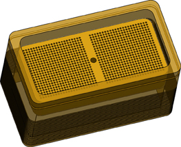
Figure 1. Chamber with the removable straight grid insert. The base of the chamber will be shaped to the contours of the monkey's skull and cemented in place.
After a two-week recovery period, we inserted the traditional straight guide grid (52 × 25 × 10 mm, made of Ultem®) into the chamber and filled the chamber with gadolinium (Magnevist, Berlex Pharmaceuticals; 1:1200 dilution in sterile saline, pH 7.0–7.5) to illuminate the grids holes in the MR images (Figure 2). Then, a high-resolution T1-weighted whole-brain anatomical scans (voxel size: 0.5 × 0.5 × 0.5 mm3) was acquired to map the grid and the brain structure by using a 4.7T Bruker scanner with a Modified Driven Equilibrium Fourier Transform (MDEFT) sequence.
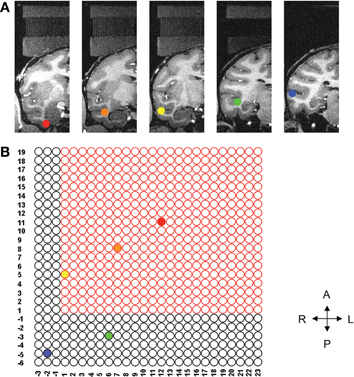
Figure 2. Location of each of five ROIs and corresponding grid holes. (A) Five ROIs in the coronal plane, each of them marked by different color. (B) Illustrates the five sites needed for the study on the grid. Only the three sites inside the bounded box can be reached using the conventional straight grid; the remaining two sites are beyond the reach of the straight grid. The left hemisphere (not shown) also had three sites that could be reached with the straight grid and two sites out of reach of the straight grid.
Targeting the ROIs
Five ROIs were selected from each hemisphere. Only the right side is shown for clarity (see Figure 2A). Using the AFNI (Analysis of Functional NeuroImages) software (Cox, 1996), we determined the corresponding grid hole that we should use if we wanted to use the straight grid (Figure 2B). The grid holes in red are those of the straight grid. As shown in this figure, the straight grid could reach only three targets, (yellow, orange, and red), inside of the bounding box that represented the perimeter of the straight grid. Obviously, a single angled grid could not reach all of the bilateral targets. Moreover, even a grid with two separate angles (one for each hemisphere) was not adequate to solve our problems because the angle in anterior-posterior direction would reduce the area we could reach due to intersection with the walls of the recording chamber such that there were several targets which remained unreachable (Figure 3). To overcome these limitations, a new type of grid was designed as follows.
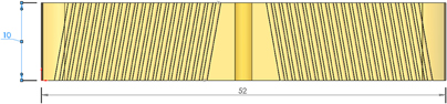
Figure 3. Grid insert with two distinct angles. This scheme leaves a large trapezoidal section in the middle of the brain ROI unreachable. Dimensions in millimeter.
Solid Modeling
For the example presented here, 10 points were determined by depth, distance right to left, and distance anterior to posterior referenced to the top center of the guide grid. Each point was assigned a color to aid in identification. A three-dimensional model of the guide grid, recording chamber, and targets of interest was created using the software SolidWorks® (Dassault Systemes SolidWorks, Concord: MA). Projection axes were created between each of the 10 target points and corresponding points on the surface of the grid. Sketch planes were created perpendicular to each axis at the depth of the target points (Figure 4). Each mapped point served as the center of a 5 mm by 5 mm square sketch that was used to create an extruded cut up through the surface of the guide grid (Figure 5). By moving the positions of the corresponding points on the surface of the grid, the final position of each of the extruded cuts could be adjusted to ensure that the 10 different cuts did not interfere with each other or intersect the recording chamber. The guide grid was now comprised of a 52 mm by 25 mm by 10 mm block with ten 5 mm by 5 mm extruded cuts, and each of these extruded cuts was angled exactly toward the point of interest from which it was derived.
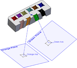
Figure 4. Sectional view of the grid insert. A plane at each injection site was created perpendicular to an axis that connected the target site and a point on the surface of the grid. Each target site was assigned a color to distinguish them one from another. For clarity, only two are shown here.
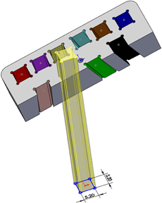
Figure 5. The 5 × 5 mm sketch used to project an extruded cut up through the grid insert. The sketch was slightly oversized (5.2 × 5.2 mm), and circular grooves at the corners were added to facilitate introduction of adhesive.
Master Grid Fabrication
This varied angle guide grid was saved in the stereolithography “.STL” file format and printed using a Dimension Elite 3D printer (Stratasys, Eden Prairie: MN). This is a significant salient feature that rendered this method feasible as conventional machining of such a grid insert would have been prohibitively expensive. Three-dimensional printing is readily available and affordable as an outside service for those institutions that do not have their own printer.
Small guide grids, 5 mm by 5 mm by 10 mm were fabricated from Ultem® (Figure 6). Each small guide grid had twenty-five 635 micron thru holes drilled on 1 mm centers. This size was decided upon to give the investigator some leeway to avoid anatomical obstructions, such as blood vessels, while still permitting a reasonable number of points to be reached by each varied angle guide grid. These small guide grids were cemented in flush with the bottom surface of the varied angle guide grid (Figure 6). This new grid system provided a 5 × 5 mm2 area for each cannula or electrode insertion site that guaranteed all 10 targets could be reached with one master grid placed in a single chamber.
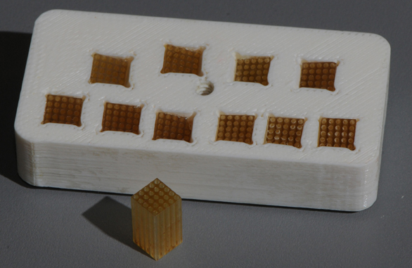
Figure 6. The 5 × 5 × 10 mm insert. Each insert contained 25 holes (diameter: 635 micron; 1 mm on center). Final master grid with 10 inserts each aimed at a specific ROI.
Pilot Study Results
The goal of our initial study was to assess targeting accuracy through this new type of grid. As described in Sections “Solid Modeling and Master Grid Fabrication”' above, a three-dimensional model was designed, based on AFNI mapping of target regions, for the master varied angled grid with ten individual square cutouts to house the individual small Ultem® guide grids. Once this master grid was fabricated, and the small guide grids had been inserted, we placed the grid system into the chamber and filled the chamber with gadolinium (1:1200 dilution in sterile saline) to illuminate the grids holes in the MR images (Figure 7A). We again acquired high-resolution T1-weighted whole-brain anatomical scans (voxel size: 0.5 × 0.5 × 0.5 mm3). Using AFNI software, the ideal grid holes, as well as the lengths of the guide and infusion cannulae, required to reach the target sites, were established. Based on the calculation, all the 10 ROIs can be reached by using this new grid. These theoretical calculations were verified by the following experiment. Following aseptic protocol, a sterile field was prepared and using sterile gastight Hamilton syringes, mounted on the microliter rack of an infusion pump (Harvard Apparatus) and connected to the infusion cannula (30 gauge stainless steel). After inserting guide tubes (24 gauge stainless steel) into the intended grid holes, the infusion cannulae were lowered into place and we made microinfusions (2.7–3.75 μl/site, at rates ranging from 0.18 to 0.25 μl/min) of the MR contrast agent gadolinium (1:75 dilution in sterile saline, pH 7.0–7.5) into the circumscribed ROIs in the temporal cortex of the awake monkey prior to MR scan sessions. Based on the T1-weighted scans collected following these injection sessions, we were successfully able to inject the gadolinium solution into each site in an efficacious manner, demonstrating the viability of this new targeting technique (see Figure 7B).
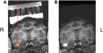
Figure 7. (A) One ROI, shown here in the coronal plane, rotated into the coordinate system of the guide grid, the ROI marked as an orange disk. (B) The actual injection results made though this angled grid.
Discussion
In the present study, a new type of 3D printed grid insert system, which is capable of accommodating multiple angles simultaneously, was designed and proven to be a productive scheme for expanding the reach of the electrodes and/or injection cannulae aimed at sites deep in the brain. This type of grid insert system would have applications in a variety of experiments (see target areas in Hernández et al., 2010; Maior et al., 2010; Vallentin and Nieder, 2010), allowing concurrent access to several ROIs, including bilateral targeting, from a single-stage surgical preparation.
Alternatives and Considerations
An equally valid but different approach to the problem of simultaneous multi-angle targeting of multiple brain regions would be the use of an array of permanent indwelling individual guide cannulae (as available through Plastics One, Roanoke: VA, for instance). Such cannulae can be obtained in MR compatible materials (fused silica), allowing for anatomical scanning to validate target acquisition, as well as functional imaging experiments. One caveat, however, is that this method is far less flexible than a grid based system, as modification of the target acquisition may require additional intervals for placement surgeries. Both methods could be combined effectively of course, for targeting of tissues by trajectories originating from more caudal or lateral points. For example, such combination would retain the capacity for flexible, simultaneous bilateral targeting of ROIs in frontal as well as temporal cortices via this new multi-angle grid system, while hippocampal tissue could be approached longitudinally (see Hampton et al., 2004), via chronic indwelling guide cannulae.
Future Developments
Future work will test the feasibility of adapting this technique for use with recording electrodes. This will involve modification of a microdrive (Nichols et al., 1998) to control the placement of the electrode to conform to the appropriate angle. The device and techniques described in the current study provide a useful method to reach injection sites well beyond of the vertical reach of a single recording chamber. This multi-angle guide grid system takes advantage of the capabilities offered by the Dimension Elite 3D printer (Stratasys, Eden Prairie: MN) and is an affordable alternative to conventional machining options. These factors combine to maximize flexibility during the course of an experiment, allowing issues that might arise, such as vascular obstacles, or gliosis, to be circumvented by changing an angle of approach and printing a new guide grid to achieve placements in the target ROI. Such flexibility would be beneficial for target trajectories passing near ventricles (see Bouret and Richmond, 2009; Maior et al., 2010), bilateral targeting (see Dunn and Colby, 2010), and regions with rich vascular challenges (see Singer and Sheinberg, 2010; Hayden et al., 2011).
Conflict of Interest Statement
The authors declare that the research was conducted in the absence of any commercial or financial relationships that could be construed as a potential conflict of interest.
Acknowledgments
We thank the NIF facility including Dr. Frank Ye and Charles Zhu for assistance with scanning. This project was fully funded by the Intramural Research Program of NIMH, NICHD, and NINDS/NIH/DHHS.
References
Bouret, S., and Richmond, B. J. (2009). Relation of locus coeruleus neurons in monkeys to Pavlovian and operant behaviors. J. Neurophysiol. 101, 898–911.
Cox, R. W. (1996). AFNI: software for analysis and visualization of functional magnetic resonance neuroimages. Comput. Biomed. Res. 29, 162–173.
Crist, C. F., Yamasaki, D. S. G., Komatsu, H., and Wurtz, R. H. (1988). A grid system and a microsyringe for single cell recording. J. Neurosci. Methods 26, 117–122.
Dias, E. C., and Segraves, M. A. (1999). Muscimol-induced inactivation of monkey frontal eye field: effects on visually and memory-guided saccades. J. Neurophysiol. 81, 2191–2214.
Dunn, C. A., and Colby, C. L. (2010). Representation of the ipsilateral visual field by neurons in the macaque lateral intraparietal cortex depends on the forebrain commissures. J. Neurophysiol. 104, 2624–2633.
Eifuku, S., Nakata, R., Sugimori, M., Ono, T., and Tamura, R. (2010). Neural correlates of associative face memory in the anterior inferior temporal cortex of monkeys. J. Neurosci. 30, 15085–15096.
Evarts, E. V. (1968). A technique for recording activity of subcortical neurons in moving animals. Electroencephalogr. Clin. Neurophysiol. 24, 83–86.
Hampton, R. R., Buckmaster, C. A., Anuszkiewicz-Lundgren, D., and Murray, E. A. (2004). Method for making selective lesions of the hippocampus in macaque monkeys using NMDA and a longitudinal surgical approach. Hippocampus 14, 9–18.
Hayden, B. Y., Heilbronner, S. R., Pearson, J. M., and Platt, M. L. (2011). Surprise signals in anterior cingulated cortex: neuronal encoding of unsigned reward prediction errors driving adjustment in behavior. J. Neurosci. 31, 4178–4187.
Hernández, A., Nácher, V., Luna, R., Zainos, A., Lemus, L., Alvarez, M., Vázquez, Y., Camarillo, L., and Romo, R. (2010). Decoding a perceptual decision process across cortex. Neuron 66, 300–314.
Maior, R. S., Hori, E., Tomaz, C., Ono, T., and Nishijo, H. (2010). The monkey pulvinar neurons differentially respond to emotional expressions of human faces. Behav. Brain Res. 215, 129–135.
Nichols, M. J., and Newsome, W. T. (2002). Middle temporal visual area microstimulation influences veridical judgments of motion direction. J. Neurosci. 22, 9530–9540.
Nichols, A. H., Ruffner, T. W., Sommer, M. A., and Wurtz, R. H. (1998). A screw microdrive for adjustable chronic unit recording in monkeys. J. Neurosci. Methods 81, 185–188.
Pickens, C. L., Adams-Deutsch, T., Nair, S. G., Navarre, B. M., Heilig, M., and Shaham, Y. (2009). Effect of pharmacological manipulations of neuropeptide Y and corticotropin-releasing factor neurotransmission on incubation of conditioned fear. Neuroscience 164, 1398–1406.
Saleem, K. S., Pauls, J. M., Augath, M., Trinath, T., Prause, B. A., Hashikawa, T., and Logothetis, N. K. (2002). Magnetic resonance imaging of neuronal connections in the macaque monkey. Neuron 34, 685–700.
Simmons, J. M., Saad, Z. S., Lizak, M. J., Ortiz, M., Koretsky, A. P., and Richmond, B. J. (2008). Mapping prefrontal circuits in vivo with manganese-enhanced magnetic resonance imaging in monkeys. J. Neurosci. 28, 7637–7647.
Singer, J. M., and Sheinberg, D. L. (2010). Temporal cortex neurons encode articulated actions as slow sequences of integrated poses. J. Neurosci. 30, 3133–3145.
Vallentin, D., and Nieder, A. (2010). Representations of visual proportions in the primate posterior parietal and prefrontal cortices. Eur. J. Neurosci. 32, 1380–1387.
Keywords: neuronal activity, recording chamber, guide grid, solid modeling, three-dimensional printing
Citation: Talbot T, Ide D, Liu N and Turchi J (2012) A novel, variable angle guide grid for neuronal activity studies. Front. Integr. Neurosci. 6:1. doi: 10.3389/fnint.2012.00001
Received: 31 October 2011; Paper pending published: 04 December 2011;
Accepted: 05 January 2012; Published online: 20 January 2012.
Edited by:
Hermann J. Mueller, University of Munich, GermanyReviewed by:
Toemme Noesselt, Otto-von-Guericke-University, GermanyPatrizia Fattori, University of Bologna, Italy
Copyright: © 2012 Talbot, Ide, Liu and Turchi. This is an open-access article distributed under the terms of the Creative Commons Attribution Non Commercial License, which permits non-commercial use, distribution, and reproduction in other forums, provided the original authors and source are credited.
*Correspondence: Thomas Talbot, Laboratory of Cellular and Synaptic Neurophysiology, Eunice Kennedy Shriver National Institute of Child Health and Human Development, National Institutes of Health, 13 South Drive Room G360, Bethesda, MD 20892-5712, USA. e-mail:dGFsYm90dEBtYWlsLm5paC5nb3Y=