 David Trebotich1*
 Randolph R. Settgast2Terry Ligocki1William Tobin3Gregory H. Miller1
 Sergi Molins4
 Carl I. Steefel4
- 1Lawrence Berkeley National Laboratory, Applied Mathematics and Computational Research Division, Berkeley, CA, United States
- 2Lawrence Livermore National Laboratory, Atmospheric, Earth and Energy Division, Livermore, CA, United States
- 3Lawrence Livermore National Laboratory, Applications, Simulations and Quality Division, Livermore, CA, United States
- 4Lawrence Berkeley National Laboratory, Energy Geosciences Division, Berkeley, CA, United States
Predicting the evolution of fractured media is challenging due to coupled thermal, hydrological, chemical and mechanical processes that occur over a broad range of spatial scales, from the microscopic pore scale to field scale. We present a software framework and scientific workflow that couples the pore scale flow and reactive transport simulator Chombo-Crunch with the field scale geomechanics solver in GEOS to simulate fracture evolution in subsurface fluid-rock systems. This new multiphysics coupling capability comprises several novel features. An HDF5 data schema for coupling fracture positions between the two codes is employed and leverages the coarse resolution of the GEOS mechanics solver which limits the size of data coupled, and is, thus, not taxed by data resulting from the high resolution pore scale Chombo-Crunch solver. The coupling framework requires tracking of both before and after coarse nodal positions in GEOS as well as the resolved embedded boundary in Chombo-Crunch. We accomplished this by developing an approach to geometry generation that tracks the fracture interface between the two different methodologies. The GEOS quadrilateral mesh is converted to triangles which are organized into bins and an accessible tree structure; the nodes are then mapped to the Chombo representation using a continuous signed distance function that determines locations inside, on and outside of the fracture boundary. The GEOS positions are retained in memory on the Chombo-Crunch side of the coupling. The time stepping cadence for coupled multiphysics processes of flow, transport, reactions and mechanics is stable and demonstrates temporal reach to experimental time scales. The approach is validated by demonstration of 9 days of simulated time of a core flood experiment with fracture aperture evolution due to invasion of carbonated brine in wellbore-cement and sandstone. We also demonstrate usage of exascale computing resources by simulating a high resolution version of the validation problem on OLCF Frontier.
1 Introduction
The Exascale Computing Project (ECP) Subsurface Application Code Development Project supported by the US Department of Energy has aimed to solve fracture evolution in wellbore cement at unprecedented scale and resolution for the purpose of wellbore integrity assessment in carbon sequestration. In particular, high fidelity modeling of multiphysics coupling of flow, transport, reactions and mechanics in wellbore cement for domains on the order of centimeters with pore scale resolution is critical to the prediction of fracture evolution, and, thus, potential of risk, in carbon sequestration sites. This simulation problem—up to 10 cm domains with micron-scale resolution—is an exascale computing challenge, requiring both performance and memory bandwidth beyond CPU-based machines. In order to achieve this exascale challenge, codes need to be performance portable on next generation exascale architectures, specifically for GPU acceleration, but also new multiphysics capabilities must be developed to solve the multiphysics problem of coupled flow, transport, reactions, and mechanics. As a result, we have developed a coupling framework and scientific workflow that combines two methodologically different code bases: the high resolution pore scale flow and reactive transport capabilities of Chombo-Crunch, and the large scale geomechanics code, GEOS. We present the multiscale, multiphysics coupling algorithm, and demonstrate verification and validation as a viable approach to an exascale challenge problem.
1.1 Impact
The geologic subsurface constitutes the United States' primary source of energy and also provides a vast amount of storage critical to a low-carbon and secure energy future. At the same time, world energy demand is steadily increasing, pressure to reduce climate impacts is growing, and concern regarding water quality and quantity is also rising. Consequently, there are multiple, urgent drivers for more efficient utilization of subsurface resources while reducing environmental impact. The safe and efficient use of the subsurface, however, requires a sound understanding of and predictive capability for the coupled thermal, hydrological, chemical, and mechanical (THCM) processes that ultimately control the success or failure of many energy related endeavors in the subsurface including: geologic CO2 sequestration, petroleum extraction, geothermal energy and nuclear waste isolation.
For example, development of renewable geothermal energy by its very nature involves strongly coupled thermal-hydrological-mechanical processes by design. In addition, chemical processes (such as scaling) can lead to long-term degradation of heat exchange. Stimulation is often required to efficiently extract heat from the rock mass. Understanding and optimizing these processes requires understanding how coupled processes at small scales impact the emergent behavior of the geothermal system. For example, at a relatively modest computational scale, it was demonstrated that the variations in aperture within a rough fracture can couple with thermal stresses to enhance channelization of flow in geothermal systems and reduce heat exchange (Fu et al., 2015). Such studies, however, have been limited by computational resources to consider either a small portion of the geothermal system, or make limiting assumptions to allow for scale up. The computational tool we propose here will be directly applicable to these classes of systems at a scale not previously possible.
It is currently impossible to model a full geological system, with reservoir, caprock, multiple wells, and other potential leakage pathways, to assess risk using current software and HPC. Consequently, risk analysis of geological energy or waste storage or geothermal systems requires simplified approaches and cannot be predictive of risk. For example, most approaches to risk-analysis in the subsurface are scenario based. Such approaches need to assume a range of plausible events for which probabilities and impacts can be assessed. This assumes that the failure modes of the system are known a priori. In contrast, the development of large scale geological system models, including the necessary details at scales where processes couple, promises a more predictive approach where the potential failure modes emerge from the model rather than being predetermined.
1.2 Multiscale, multiphysics simulation
Critical to the success of modeling subsurface problems of interest to US energy security is the ability to predict multiphysics and chemistry behavior on a macroscopic scale—such as a geologic reservoir in the subsurface. For the subsurface, this is typically accomplished by modeling thermal, hydrological, chemical and mechanical, or THCM, multiphysics processes using a continuum Darcy model for flow, large scale finite element models for geomechanics and effective medium models for reactions which make use of averaged parameters for rates. While this approach has been applied for many years, and successfully, the more recent emergence of pore scale experiments and modeling and simulation have illuminated the need for multiscale approaches to multiphysics coupling (Molins et al., 2012, 2014, 2017; Trebotich et al., 2014). Existing macromodels do not represent and cannot capture microscale emergent processes which can evolve into large scale dynamics over time. Examples of these types of emergent processes include dissolution of subsurface asperities on the micron scale causing local fracture collapse when CO2 is injected into an underground reservoir (km scale).
One urgent challenge is to understand and predict the reservoir-scale behavior as affected by the long-term integrity of the hundreds of thousands deep wells that penetrate the subsurface for resource utilization. The performance of a wellbore hinges on the behavior of very thin interface features controlling the leakage of fluids along the well casing-cement boundary that extend over kilometer distances along the well. Similarly, leakage of buoyant fluids (e.g., CO2) through caprocks may be controlled by micron-scale asperities in fracture networks that are themselves subject to geomechanical and geochemical modification. The multiphysics response of subsurface caprock materials (including nanoporous shales) to perturbations from mechanical and chemical stressors is a coupled mesoscale behavior that is not well understood or predictable at the pore scale, and is even more challenging when upscaling to the core and reservoir scale where questions about resource utilization and storage security ultimately need to be answered.
At the reservoir or field scale (~1–10 km domain size), multiphase flow and reactions in fractured porous media are typically modeled using continuum models that make use of averaged quantities and bulk parameters that do not fully take into account THCM-related heterogeneity at different spatial and temporal scales. As such, permeability values used in field scale hydrological models are an average over the entire fracture length when, in reality, the aperture can vary widely from say 1 μm to 1 cm. A more rigorous treatment is to resolve the pore-scale (0.1–10 micron) physical and geochemical heterogeneities in wellbores and fractures so as to improve our ability to predict the evolution of these features when subjected to geomechanical and geochemical stressors. Pore scale modeling resolves flow and transport in the pore space, precisely computing permeability and other porous medium properties such as reactivity and diffusivity. These parameters can then be upscaled into field scale models. For this upscaling to be effective, the pore scale must be simulated on a domain the size of a representative elementary volume (REV) of the field scale (~1 mm−1 cm). The ultimate challenge, therefore, is to integrate the complex multiphysics processes occurring at multiple scales, from the micro- to the kilometer scale, in a high resolution reservoir simulator. Meeting this challenge will require the use of innovative multiscale coupling approaches, and ultimately, exascale computing.
As a result of the DOE ECP newly established exascale application codes can model individual scales with high fidelity, challenging current understanding of what it means to be an REV of the continuum scale in heterogeneous media (Trebotich, 2024). In fact, micromodel simulations themselves applied brute force at unprecedented scale and resolution produce vast amounts of data which have come to comprise ground truth science. Combining this new information with recent developments in the software coupling of individual scale capabilities creates an opportunity to perform dynamic data-informed multiscale, multiphysics simulation, which has been the holy grail in simulation science.
1.3 Exascale challenge problem
Our ultimate target problem is prediction of non-isothermal multiphase fluid flow and reactive transport, chemical and mechanical effects on formation properties, induced seismicity, and reservoir performance for energy storage and recovery applications. The primary focus will be on subsurface energy systems impacted by strong flow and/or chemical heterogeneity that could impact fluid leakage or engineered reservoir performance. An example application would be to simulate an entire field of wellbores and their interaction through the reservoir over 100 year time scales. Another problem of similar importance and complexity is the simulation of the geomechanical and geochemical evolution of a fracture system potentially impacting caprock integrity, with length scales up to 1 km informed by pore scale features and processes. A vast range of scales is necessary to capture the physics of flow and reaction in fractures and wellbore casings (0.1 to 10 microns) that ultimately govern the performance and risk of the reservoir (kilometer scale). Poor wellbore performance has been identified as a dominating factor in the contamination of drinking water aquifers due to hydraulic fracturing and potential loss of containment in CO2 sequestration. Understanding wellbore integrity is essential for protecting water supplies in locations such as California in particular where water and oil resources are frequently in close proximity and water supplies are in critical demand. The reality is that wellbore performance is the result of a complicated physical-chemical-thermal interaction between an engineered system (e.g., metal components, and cements) and the natural surroundings (e.g., rock, reactive fluids, oil, and gas). Only recently has it become possible to simulate some of the coupled processes associated with these complex systems, albeit over a very limited scale range (Carroll et al., 2013; Walsh et al., 2014a,b). The number of coupled processes and length scales within these systems make them impossible to study with current HPC hardware where deleterious impacts develop in field. Specifically, one pressing challenge is that the performance of a wellbore hinges on the micro-scale behavior of very thin interface features that control leakage of fluids (the well casing-cement boundary, for example) that extend over kilometer distances along the well. Questions about resource utilization and storage security ultimately need to be answered on the scale of entire reservoirs, which are often affected by the hundreds to thousands of wells.
For this paper we present the baseline capability to simulate the multiscale, multiphysics processes of the exascale challenge problem: coupled, single phase flow, transport, reactions and geomechanics in wellbore cement and surrounding carbonate rock matrix fractures up to 10 cm in length with 1 micron pore scale resolution. This multiphysics capability combines large scale flow and geomechanics with pore scale flow and reactive transport to model fracture evolution in wellbore cement and surrounding rock, necessitating advanced coupling of two different numerical methodologies at two different scales. The pore scale resolution alone requires exascale resources as it models 100s of billions of degrees of freedom assuming fracture apertures of <1 mm and fracture widths <1 cm. The target computing architecture is the Frontier exascale supercomputer at Oak Ridge Leadership Computing Facility (OLCF) which requires performance portability and engineering of the multiphysics simulation capability on GPUs.
2 Approach
For this challenge problem we developed a scientific workflow and software framework that combines the two application codes—Chombo-Crunch and GEOS—to solve coupled multiphysics processes associated with subsurface fracture evolution. Chombo-Crunch is a pore scale reactive transport simulator and models the inside of fractures and a layer of rock matrix outside the fracture; GEOS is a continuum scale flow and mechanics simulator that can model wellbore systems at the field scale. We developed a coupling framework in Chombo based on an HDF5 data schema that is only restricted by the coarse scale grids in GEOS. A novel time stepping strategy is presented for the coupling of the multiphysics, multiscale time scales.
2.1 Chombo-Crunch
Chombo-Crunch is a suite of HPC application codes that simulates flow, transport and reactions in heterogeneous media like the geologic subsurface (chombo.lbl.gov). Chombo-Crunch makes use of Chombo geometry and grid generation software based on embedded boundary (EB) representations derived from implicit functions on a grid. In particular, reactions are treated at the pore scale using the embedded boundary to explicitly resolve reactive surface area inside the fracture resulting in surface reactions that dissolve or precipitate mass of the rock matrix surrounding the interface. Chombo-Crunch makes use of fast linear solvers for elliptic problems in the flow and transport equations based on the PETSc software libraries (petsc.org) that access hypre (github.com/hypre-space/hypre) algebraic multigrid solvers (Trebotich et al., 2014). Chombo-Crunch has been applied to a wide range of pore scale and multiscale subsurface flow reactive transport problems (Molins et al., 2012, 2014, 2017, 2019; Deng et al., 2018).
Geologic media and materials are highly irregular and dense, and can be nanoporous. Complex geometries have more traditionally been treated with conforming grids, especially in the finite element community. For the arbitrarily complex geometries that present in the geologic subsurface traditional structured or unstructured grid generation techniques are too time-consuming and involve much user interaction. It is difficult to generate grids that both preserve the fidelity of the geometry and lead to robust solvers for the PDEs. Furthermore, if performing direct numerical simulation from image data of nanoporous materials such as those found in subsurface systems, the gridding and discretization techniques need to be consistent for the approach to be viable and computationally efficient. The meshing technique used for gridding the geometry must be amenable to surface extraction from experimentally derived image data obtained from core samples of geologic media; and the computational model should be able to directly simulate flows on the meshes obtained from imagery without loss of geometric detail in a fast, accurate, stable and conservative manner. The adaptive embedded boundary approach in Chombo-Crunch affords this kind of consistency between tractable gridding and efficient discretization (Trebotich and Graves, 2015).
2.2 GEOS
GEOS (geos.dev) is an open-source multiphysics framework designed for the simulation of a wide range of subsurface problems from hydraulic fracturing of unconventional reservoirs, to the fracture of solids at high loading rates. The goal of GEOS is to open up new horizons in modeling carbon storage and other subsurface energy systems including taking advantage of the ongoing revolution in high-performance computing hardware, which is enabling orders-of-magnitude gains in performance, but also forcing a fundamental rethink of our software designs; enriching the physics used in industrial simulations, allowing complex fluid flow, thermal, and geomechanical effects to be handled in a seamless manner; developing highly-scalable algorithms for solving these coupled systems; and improving workflows for modeling faults, fractures, and complex geologic formations. GEOS is released under an LGPL-v2.1 license.
Various physics-based solvers are built into GEOS. Each solver is either a self-contained set of functions geared toward solving a specific PDE, or a wrapper that defines a method by which to couple other physics solvers. For example, to simulate the hydraulic fracturing problem, GEOS utilizes a fully coupled approach where a solver that provides a finite element solution to the equations of motion are applied to the solid rock, and a solver that provides a finite volume solution for fluid flow is applied to the fluid in the fracture. The FEM implementation in GEOS currently has a classic structure where iteration is done over the elements, and matrix/rhs contributions are aggregated. Then the time integration method is applied (e.g., matrix solution), and the mesh positions are updated. Of specific interest for the proposed coupling with Chombo-Crunch, GEOS also contains a flexible implementation of contact detection/enforcement that enables the upscaled simulation of partially closed fluid filled fractures. GEOS has been applied to problems such as field scale hydraulic fracturing, enhanced geothermal production studies, microscale modeling of chemo-mechanical evolution of fractures, and the dynamic fracturing of geologic materials.
2.3 Multiphysics coupling algorithm
The coupling of Chombo-Crunch and GEOS is performed via a framework that makes use of an HDF5 data schema for transfer of data between the two codes. There are two representations of the interface between fluid and rock. GEOS uses a lower resolution representation of the interface that is composed of quadrilaterals (quads) that are faces of the hexahedral cells that form its computational mesh. Chombo-Crunch maintains both a representation that GEOS uses as well as a higher resolution implicitly defined surface used for the embedded boundary grid. Chombo-Crunch maintains consistency between the two representations. Figure 1 is a high level schematic representation of the coupling framework and workflow.
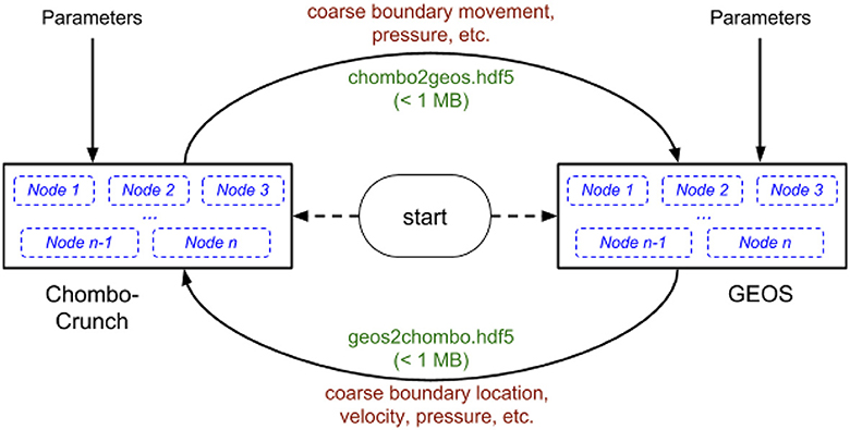
Figure 1. Schematic representation of multiphysics coupling framework and workflow.
We explain the overall coupling algorithm shown in Figure 1 by the following steps:
1. GEOS defines the initial coarse solid mesh and writes the fracture surface information into the coupling file including the following data:
a. reference nodal position
b. nodal deformation
c. surface face connectivity
d. coarse mesh fluid pressure
2. Chombo-Crunch reads the initial coarse mesh data from the coupling file and creates a consistent implicit representation of it at the higher resolution for the resolved embedded boundaries on a Cartesian grid.
3. Chombo-Crunch evolves the fluid flow, transport, and any deposition or removal of material on this boundary due to reactions.
4. Chombo-Crunch moves the reference nodal position of the coarse mesh such that the resulting (new) coarse boundary is consistent with the computations in step (3), and integrates the fine mesh pressures onto the coarse mesh surfaces. Moving of the reference nodal positions and computing the corresponding pressures on the coarse mesh is done by sampling, or a low-order version of integration.
5. Chombo-Crunch writes the new reference node positions and pressures on all the coarse faces into the coupling file.
6. GEOS reads the coupling data file and updates its representation of the finite element mesh to account for the material gain/loss (i.e., moves the reference nodal positions of coarse nodes). It then uses the coupling pressures to compute new nodal deformations of the solid mesh which modifies the solid representation.
7. GEOS writes the new coarse information (see step 1) into the coupling file.
8. Chombo-Crunch reads the new coarse information from the coupling file and changes the implicit higher resolution boundary representation to be consistent with the movement of the boundary due to solid mechanics. We continue to step 3 unless the computation is complete.
The two major steps in the coupling process described above involve making the coarse and fine boundary representations consistent—steps 4 and 8 above.
In step 4, we have the fine representation from the beginning and the end of the current time step in Chombo-Crunch. We have the coarse representation from the beginning of the current time step and we want to generate a coarse representation consistent with the end of the current time step. The details of this step are as follows:
1. We compute the signed distance function from fine representation for the end of the time step.
2. We compute the gradient of this function.
3. At each coarse node, we evaluate the signed distance function and gradient computed in (1) and (2) at the node's current position. This is currently done using the nearest point in the fine representation as the approximate location of node position. This could be done with more accuracy by interpolating between all the fine positions surrounding the coarse node.
4. Using this information we attempt to move the node to a place where the signed distance function is zero (i.e., the node would lie on the fine boundary representation). Our computation is only an approximation. It could be repeated to improve accuracy.
At this point the new fine and coarse representations of the boundary are considered consistent.
In step 8, we have the “old” coarse representation of the boundary from the end of the last time step and the “new” coarse representation of the boundary for the beginning of the current time step and the “old” fine representation of the boundary from the end of the last time step (which is consistent with the old coarse representation). To make a “new” fine representation of the boundary for the beginning of the current time step that is consistent with the new coarse representation, we do the following:
1. Compute the signed distance functions for the old and new coarse representations and the old fine representation.
2. Modify the signed distance function of the old fine representation using the difference between the signed distance functions of the old and new coarse representations. This effectively moves the fine representation by the amount the coarse representation has been moved by GEOS.
3. Compute a new fine representation using the modified signed distance function.
At this point the new fine and coarse representations of the boundary are, again, considered consistent.
2.4 Timestepping cadence
The overall timescale of the multiphysics coupling algorithm is governed by the reactions at the fracture boundary where reaction rates can cause dissolution or precipitation of the surface exposed to the reacting fluid. The timescale for these governing processes can be on the order of 100–200 seconds for carbonate chemistry or longer (up to a few 1,000 seconds) depending on the problem. The reaction rates will likely be different but remain large for the separated scale approach to hold. Here we test the multiphysics coupling with a calcium carbonate rock matrix. In order to integrate these timescales we make use of a combination of separated scales, equilibrium processes and quasi-static behavior. Table 1 contains the individual time scales involved in the coupled multiphysics problem. Some of the processes are not included in the algorithm because they are optional (explicit mechanics, coupled transport in rock matrix) and noted with an asterisk.
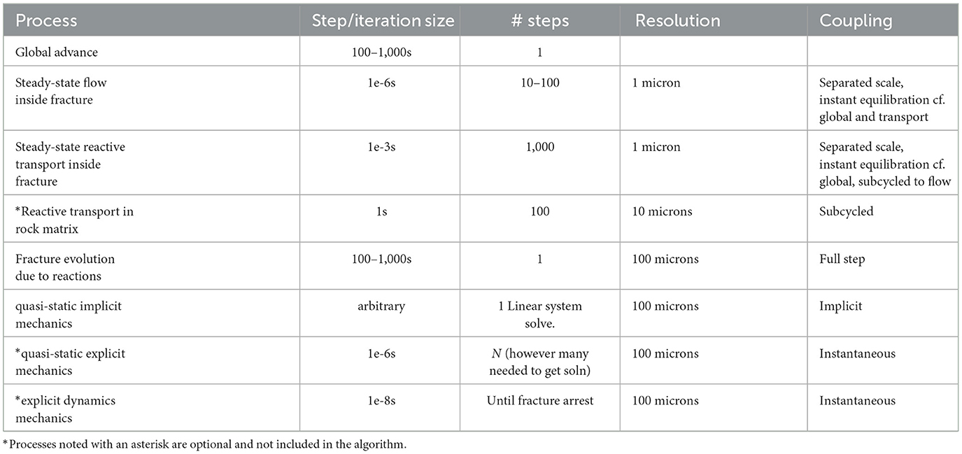
Table 1. Relevant time scales for multiphysics coupling framework cadence.
To couple these disparate scales we employed a staggered split-operator approach, with subcycling as needed. A qualitative illustration of the disparate timescales for this approach is shown in Figure 2. The cadence is listed as follows:
1. GEOS quasi-static deformation to obtain initial equilibrium location.
2. Chombo-Crunch fluid dynamics to a steady-state solution, approximately 10–100 iterations.
3. Chombo-Crunch transport, subcycled to global reaction step to obtain equilibrium solution, approximately 100 iterations.
4. Global reaction step by Chombo-Crunch moves EB in a dynamic single step, O (100 s) seconds.
5. GEOS quasi-static deformation to obtain new equilibrium location due to fluid pressures.
6. Repeat 2–5.
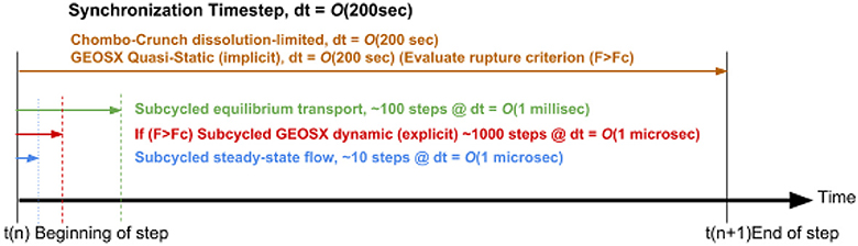
Figure 2. Global algorithm time stepping cadence.
2.5 Coupling software framework
The software framework used to exchange data between GEOS and Chombo utilizes a parallel HDF5 (exaHDF5) abstraction layer to serve as the common data platform between the two codes. The sequence of events that define the algorithm for the coupling framework is specified as follows. GEOS sends data that defines the boundary between solid rock and a fluid, and data that defines the state of materials, as a mesh of quadrilaterals to the abstraction layer. Chombo receives this data from the abstraction layer and generates an appropriate EB cut-cell representation from that data. Chombo runs through a flow simulation, and passes pressures on each quadrilateral face, at the GEOS resolution, to the abstraction layer. Then GEOS uses the pressures to run a quasi-static simulation to generate new estimates for the surface position. While the Chombo resolution is significantly higher than that of GEOS for the challenge problem, the coupling data size corresponds to data resolution of the GEOS mesh.
On the GEOS side, the coupling data written and read by GEOS scales with the GEOS resolution and the domain length. The number of cores on the GEOS side scales linearly with the number of quadrilaterals in its explicit boundary representation (and other physical quantities, e.g., pressure). There is also a fairly uniform distribution of quadrilaterals per core; the HDF5 communication infrastructure also (weak) scales at these data sizes. In addition, the data size on the GEOS side is much smaller and so absolute times in the coupling code are also much smaller. In addition, Chombo and GEOS use common code to read and write the coupling data so the scaling of this code is being measured directly in the Chombo timings presented below.
On the Chombo side, more processors are used as the domain size increases. Computational costs can result from the algorithm to interpret the GEOS geometric data and translate it into a Chombo geometric representation of the fracture. In particular, holding the Chombo resolution fixed, the amount of geometry, i.e., quadrilaterals, grows with the square of the GEOS resolution increase. This growth occurs while holding Chombo computational resources constant and so could result in a quadratic increase in time spent in the coupling code as the GEOS resolution increases. To address this problem, we consider how the geometry data changes as the GEOS resolution increases. The amount of data goes up with the square of the resolution increase; but, the physical size of the domain doesn't change. Thus, the area of each of the data elements goes down as the square of the resolution increases. We can exploit this fact.
The coupling software itself is a Chombo-based code that manages the communication of node positions that define the fracture surface in GEOS and the embedded boundaries that define the analogous representation of the fracture in Chombo. The coupling framework in Chombo manages both the pore scale representation of the fracture surface that is modeled by Chombo-Crunch and a coarse grid representation of the GEOS node positions resulting from mechanical deformation. There are two Chombo software classes that support this functionality: Moving EB, which responds to forcing on the fracture interface either by reactions in Chombo-Crunch or mechanical deformation in GEOS, and EB Grid Generation, which makes the grids as a result of moving the EB.
2.5.1 EB geometry generation
The geometry generation framework within Chombo expects the geometry to be able to provide a continuous function that is negative inside the fluid, positive outside the fluid, and zero on the boundary. We assume the quadrilateral mesh generated by GEOS has been converted into a triangular mesh by simply dividing each quadrilateral along one of its diagonals. For meshes of triangles, we use the signed distance function to the mesh. This function is called at points in the physical domain needed by the geometry generation.
To keep the runtime constant for a fixed Chombo resolution we need the time of the function evaluation to remain constant for different GEOS resolutions. One way to achieve this is to require that we only examine a small number of triangles at any given point regardless of the GEOS resolution. Given that the meshes at higher resolutions are simply refinements of the lower resolution meshes, this can almost be achieved. This is done by separating the triangles into spatial “bins” and then organizing these bins into a tree structure for access. The number of triangles in each bin is kept relatively constant and small by decreasing the minimum bin size based on the average triangle size.
2.6 Tree building
Initially, we construct a spatial tree with a root node that represents the entire physical domain. All triangles are in play. We then recursively do the following:
1. Divide the current node's domain by a factor of 2 in each direction that hasn't reached the minimum size (which is set by the average triangle size of the entire mesh).
a. If the current node's domain is at or below the minimum size in all directions then this is a leaf node. Save the triangles passed in at this node and return the node representation.
b. Else cut the node's domain into a set of smaller domains.
2. For each of the smaller domains determine which of the current triangles could affect the distance function within that domain.
a. If the number of triangles is not zero, call (1) with the current smaller domain and the current triangles. When it returns, add the node it returns to your children.
b. Else, since the number of triangles is zero, this smaller domain is either entirely inside the fluid or entirely outside the fluid. Determine which, make this a leaf node which contains that information, and add this node to your children.
When this recursive procedure returns at the highest level, it results in a tree where each internal node has children representing smaller physical domains. Also, the leaf nodes either have a subset of triangles to used to compute the signed distance function or a representative value for the signed distance function.
2.7 Tree usage
We use the tree structure each time the geometry generation code needs a function value. Specifically, to find the signed distance function at a point in physical space we do the following:
1. Verify the point is in the physical domain represented by the root node. If it isn't, this is an error–the root node needs to be constructed with a physical domain that includes all points where the signed distance function will be evaluated.
2. At the current node:
a. If we aren't at a leaf node, determine which of its children contains the point, move to that node and repeat (2) with that child as the current node.
b. Else:
i. If the leaf node is all inside or all outside, return the recomputed value for the signed distance function.
ii. Else use the subset of the triangles stored at this node to determining signed distance function to the point and return that value.
There are potentially two costs associated with finding the signed distance function at a point:
1. Traversing the tree structure (step 2-a above).
2. Computing the function value (step 2-b-ii above).
Cost (1) varies as the log of the number of triangles (since they shrink in size as their number increase with the GEOS resolution) and the log of the ratio of the domain size to the triangle size. Although this cost does increase, it increases slowly and the unit cost of moving in the tree is very small so the overall costs are not significant in this case.
Cost (2) is proportional to the number of triangles at each leaf node near the boundary. Cost (2) is constant away from the boundary because it is simply returning a precomputed value. This precomputed value is stored within the tree at a leaf node that is higher in the tree than the leaf nodes which hold triangles because this leaf node represents a larger volume of space where there are no triangles. That is, the tree only descends until there are no triangles in the current node's volume or until a depth limit is reached.
2.7.1 Moving grids
The multiphysics coupling of flow, transport, reactions, and mechanics requires representation and tracking of fracture interfaces. The embedded boundary approach, in general, used in Chombo-Crunch to represent arbitrarily complex geometries is discussed in Trebotich and Graves (2015); the moving EB framework used in Chombo-Crunch is based on the algorithm described in Miller and Trebotich (2011). The implementation of this algorithm in Chombo has been shown to be robust for a wide range of problems involving time-dependent fluid-solid boundaries governed by reactions (Molins et al., 2017).
The current implementation of the moving EB code in the coupling framework performs well for smaller domains and coarse resolution while on the host. We have achieved ~10 × performance improvement of the moving EB code on the CPU, mainly by localization of global data in the advanceLevelSet routine. However, as the domain size becomes larger and the resolutions become finer as we work up to the exascale challenge problem we anticipate the need for optimization of the moving EB code (as well as the geometry generation that results from the movement, see following section). We therefore pre-emptively developed a more generic version of the moving EB code with optimizations for GPU usage. Improved performance could be obtained by additional MPI parallelism, CUDA kernels and OpenMP threading. The new moving EB code was initially developed with multiphase flow (fluid-fluid interfaces) in mind; the software infrastructure is generic to fluid-solid interfaces as well.
A central tenet of the redesigned Moving EB code is that each computation is compactly supported by a discrete implicit function data that describes interface location, curvature, and other quantities of interest. The requirement that only discrete local data be used makes the computation viable on memory-limited distributed processors including GPUs. The implicit function is a level set, defined on centers of cells containing materials of interest. This choice means that a physics-based description is available to describe the motion of the level set in time. It also means that this discrete data does not exist everywhere in the neighborhood of every interface. We have developed new high-order adaptive stencils to provide accuracy and stability in this missing-data situation which also increases arithmetic intensity of the computation. This approach to interface description also enables the simultaneous use of more than one tracked interface, which can support not only calculations involving fluid-solid interfaces but also fluid-fluid interfaces.
Furthermore, accuracy requires that the interfaces possess smoothness, which is not always possible (e.g., at the edge of a material). Thus, the geometric description of a single material by a single interface will introduce large errors near edges. However, if the material's geometry is described by a separate interface for each facet, then high-order smoothness and high-order accuracy can be attained everywhere. Interfaces with cusps, as arise during splashing on a surface, or the division of cells, can be accurately computed using this technology by treating the cusp as a point or line of separation between smooth regions, and deriving properties such as curvature from each smooth region separately.
The following source code classes from the previous moving EB implementation have been specifically rewritten in anticipation of performance findings for larger problems: ChomboSpaceNorminator, ChomboSpaceOneDMoments ChomboSpaceTimeNorminator.cpp, LSService, Geominator, Norminator, and ChomboSpaceTimeOneDMoments. We report current performance for the validation test problem below.
2.8 Performance portability
The high resolution challenge problem presented here requires the multiphysics coupling framework to run on computational resources provided by the accelerator-based architectures of exascale machines. We targeted the exascale machine Frontier at the Oak Ridge National Laboratory Leadership Computing Facility (OLCF) (We ported and tested on earlier GPU-based systems such as OLCF Summit and NERSC Perlmutter). This involves several steps to reach a validating simulation. The primary requirement is performance portability of the application codes Chombo-Crunch and GEOS to GPUs. Elliptic solvers that make use of PETSc depend on performance portability of PETSc on GPUs; reaction geochemistry in CrunchFlow is accomplished by C++ conversion and enabling CUDA. Similarly, GEOS uses RAJA and CHAI and also makes use of hypre software libraries (Bui et al., 2021). Chombo-Crunch uses PETSc to access hypre algebraic multigrid solvers.
The EB geometry generation capability in Chombo was ported to GPUs. On the CPU, this piece of code is invoked when the geometry is initially created or when it changes, as it does in the moving EB framework. Chombo geometry generation depends on implicit function representation of surfaces, which is an embarrassingly parallel process that is ripe for optimization; it has not been optimized for the results presented here. As the problem sizes get larger and geometry generation becomes more significant in performance, we optimize this process with OpenMP on the host CPU. All global data must be distributed in the Chombo parallel data iterator schema to avoid race conditions on the GPU.
3 Results
We present validation of the multiphysics coupling framework and workflow and apply the multiphysics capability to the baseline exascale challenge problem. We first validated the new multiphysics capability that combines Chombo-Crunch and GEOS to solve coupled flow, transport reactions and mechanics. Initial validation simulations were performed on NERSC Cori CPUs and the OLCF Summit GPUs as these were the platforms we had access to at the time of development, and low resolution was adequate for validation. After Frontier came online we extended the validation results to Frontier and scaled the problem to 8 × resolution necessitating the need for exascale resources.
3.1 Validation problem
We choose a validation problem based on the open channel geometry in Walsh et al. (2014a), illustrated in Figure 3. In lieu of image data from the experimental channel, we construct a channel, 3.5 cm × 0.008 cm × 0.25 cm, out of a block of material, 3.5cm × 1.5cm × 1.5cm, with 3072 × 32 × 256 cells for the pore scale simulation by Chombo-Crunch at about 10 micron resolution. The channel runs the length of the material in the x direction, is centered in the z direction, and the bottom of the channel is centered in the y direction. The boundary conditions for the fluid flow are as follows: inflow rate of 0.1 cc/min and an exit back pressure of 12.4 MPa (Walsh et al., 2014a). We used Chombo-Crunch to simulate pore scale flow, transport and reactions coupled with GEOS to simulate mechanics. Initial simulations were performed on CPUs with coarse resolution of 10 microns at the pore scale for validation. We ran 6 production runs (512 nodes, 32,768 cores) for 12 h each on NERSC Cori KNL CPUs, and the equivalent on OLCF Summit GPUs, to achieve 9 days of simulated time for comparison to the experimental results in Walsh et al. (2014a). We present simulation data for fracture evolution after 1 day and 8 days for velocity and the reacting component, calcium, in Figures 4–6, and demonstrate 9 days of simulated time in Table 2 and Figure 7 to validate results in Walsh et al. (2014a)
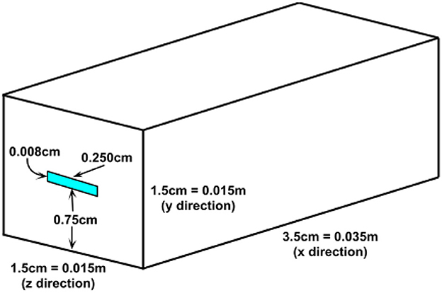
Figure 3. Illustration of the open channel problem in Walsh et al. (2014a).
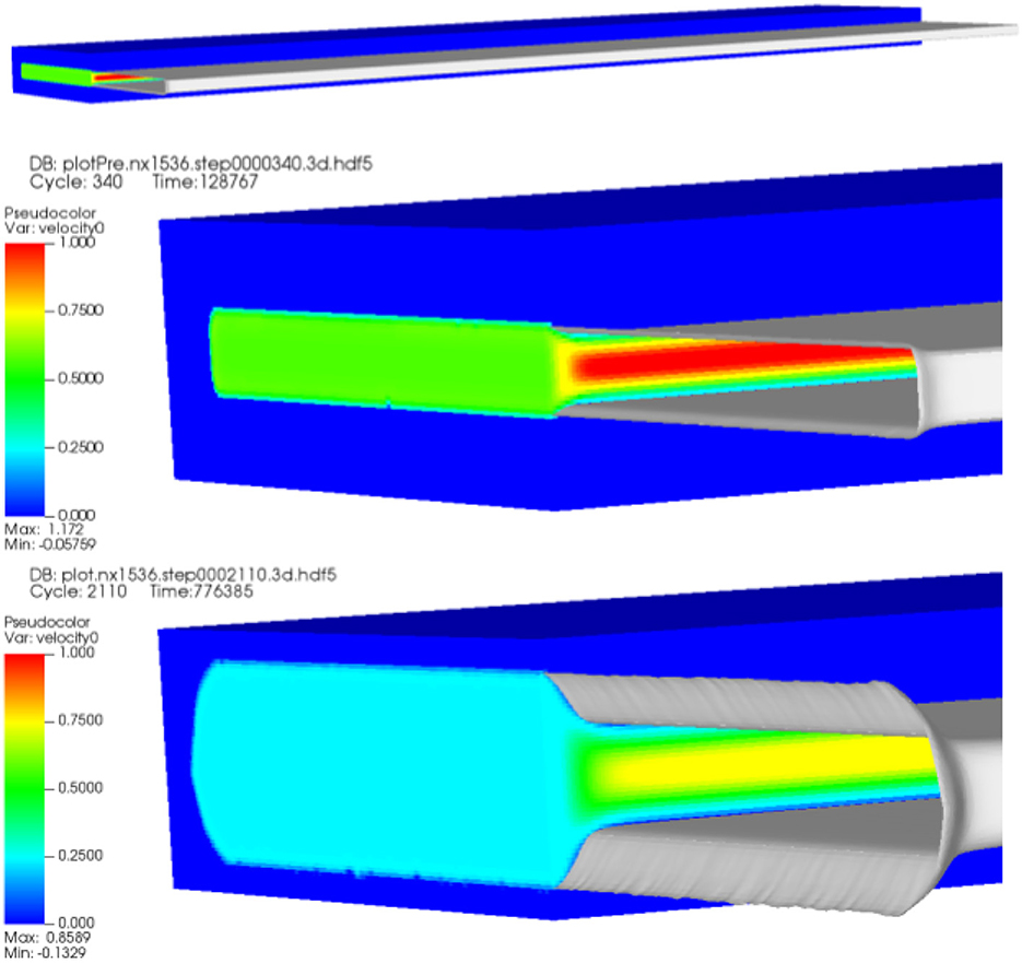
Figure 4. Computed velocity data in evolved fracture after 1 day of simulated time with closeup (top 2 figures). Computed velocity data in evolved fracture after 8 days of simulated time (bottom figure).
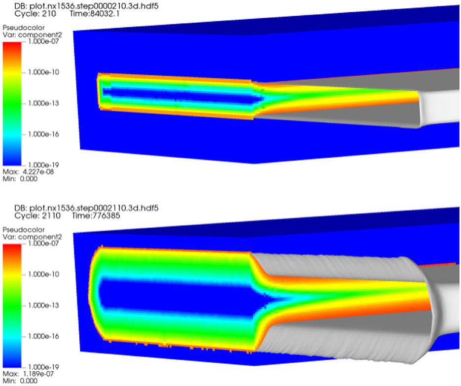
Figure 5. Computed total calcium data (log scale) in evolved fracture after 1 day and 8 days of simulated time.
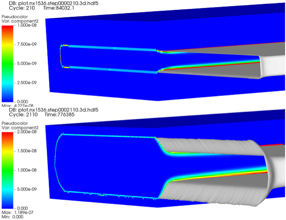
Figure 6. Computed total calcium data (true scale) in evolved fracture after 1 day and 8 days of simulated time.
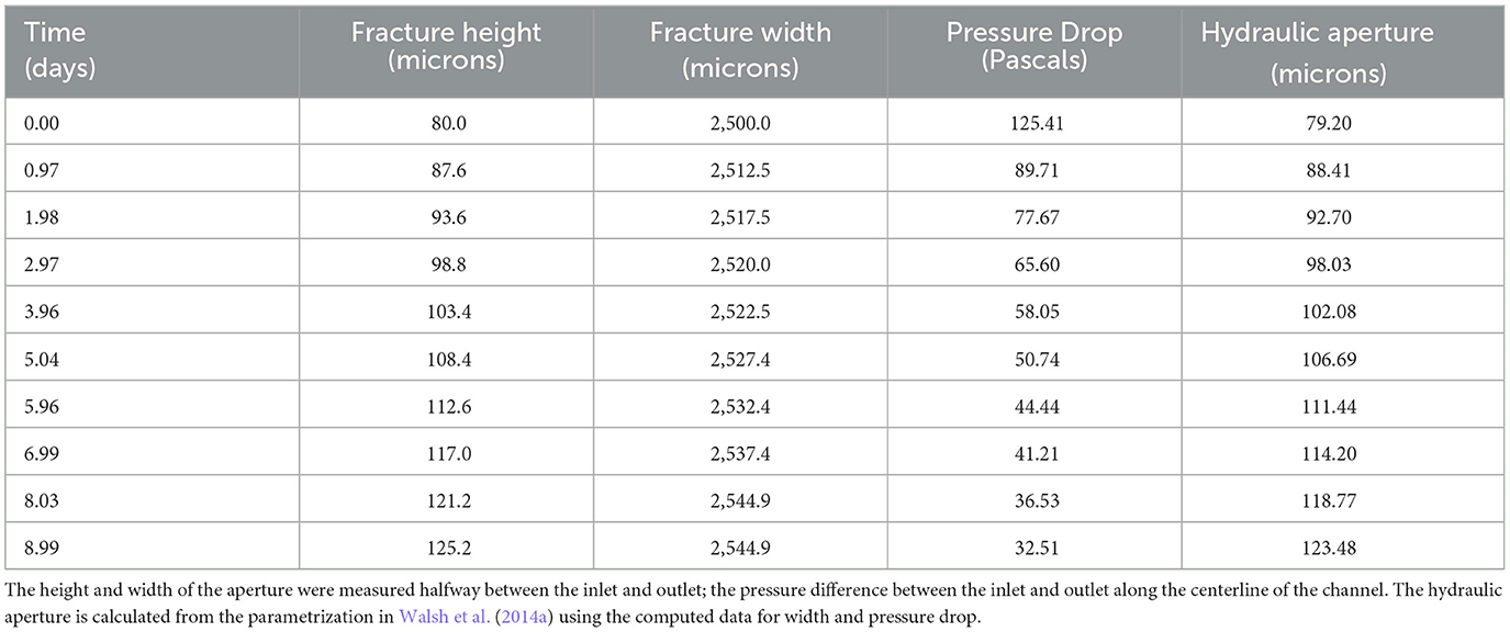
Table 2. Time evolution of fracture aperture.
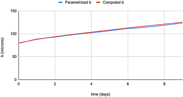
Figure 7. Comparison of fracture height as simulated to hydraulic aperture parameterization in Walsh et al. (2014a) from Witherspoon et al. (1980) using simulation data.
Simulation data for fracture evolution is shown in Table 2. We include a validation calculation of the hydraulic aperture by plugging our computed data in the parametrized equation in Walsh et al. (2014a) shown in Figure 7.
3.2 Exascale challenge problem
We initially validated the multiphysics coupling framework on CPUs on NERSC Cori then ported the capability to available GPUs on pre-exascale architectures (e.g., Nvidia V100, A100) for testing and performance portability and engineering. These validation results were extended to OLCF Frontier where we performed another round of simulations with increased resolution of 8 × from approximately 10 microns to 1 micron to demonstrate exascale capability. We used Chombo-Crunch to simulate flow, transport and reactions in a 3.5 cm fracture with 1 micron resolution, an 8 × increase in resolution over the validation problem presented above. The fracture is allowed to grow (widen) to approximately 3.5 cm × 0.036 cm × 0.29 cm, which more than covers the length scales for hydraulic aperture verification in Walsh et al. (2014a).
The 8 × increase in resolution over the lower resolution validation problem leads to a problem size of 24,576 × 256 × 2,048 cells. With 323 grid cells per box, or patch, of data in Chombo, and noting previous sweet spot load balancing and domain decomposition of 1 box per MPI rank on CPUs (Trebotich and Graves, 2015), this problem set would require 393,216 MPI processes, or 393,216 GPUs, if using a resource set of 1 GPU per MPI rank. A Frontier node comprises 4 GPUs per node, and 2 GCDs (graphics compute dies) per GPU. Therefore, due to the increased capability afforded by the Frontier architecture in terms of memory bandwidth and footprint per node, the Chombo-Crunch part of the multiphysics computation only requires 32,768 MPI ranks with 1 GCD per rank, 8 GCDs per node, or 4,096 nodes. For coupled mechanics, GEOS is run on a 3.5 × 1.5 × 0.25 cm domain with 500 microns resolution. GEOS is the large scale model and, thus, runs at a much coarser resolution and only requires one node on Frontier. Scaling of the Chombo-Crunch CFD solver is shown below in Figure 8, showing the (expected) approximate 2.5 × improvement in performance. For full details of Chombo-Crunch CFD solver scaling on Frontier, see Trebotich (2024).
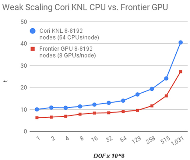
Figure 8. Weak scaling performance of CFD solver alone in Chombo-Crunch on NERSC Cori CPUs vs. OLCF Frontier GPUs. The CFD solver makes use of the same fast linear solvers in conservative transport (advection-diffusion) algorithm of the full Chombo-Crunch code accessed through the Chombo-PETSc interface and is thus reflective of transport performance, too.
We simulate 10 multiphysics coupling events between Chombo-Crunch and GEOS. Each coupling event requires about 1–2 h of wallclock time and simulates approximately 1 h of simulated time. Each coupling event includes 10 steps of fracture flow subcycling in Chombo-Crunch, 10 steps of reactive transport sub-cycling in Chombo-Crunch, 1 step in which the location of the fracture wall is modified due to reaction in Chombo-Crunch and one quasi-steady mechanics step in GEOS. The base challenge problem is specified in Table 3.
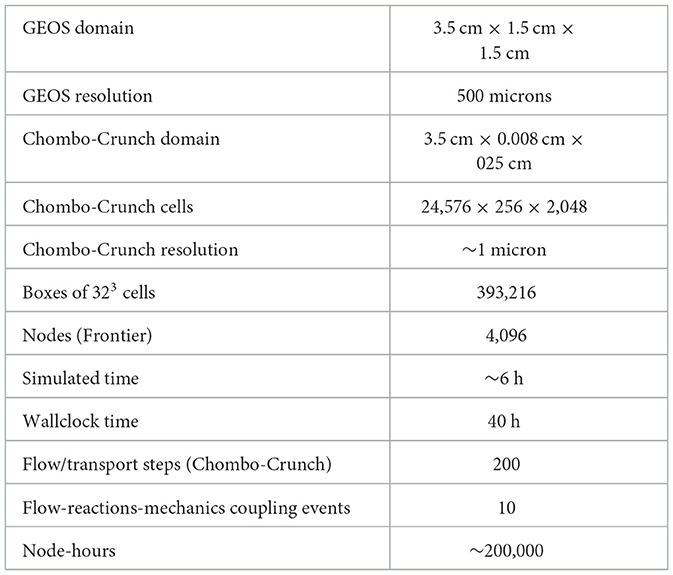
Table 3. Problem specification for the ECP Subsurface baseline science challenge.
4 Discussion
We have presented a multiphysics coupling framework and scientific workflow for fracture evolution in the geologic subsurface. The results compare well to the experimental results in Walsh et al. (2014a) which have been reduced to a bulk parameterization of hydraulic aperture derived from Witherspoon et al. (1980). The authors in Walsh et al. (2014a) state that “the hydraulic aperture is not a true measure of length but a quantity derived from the fracture's ability to transmit fluid.” In our simulations we are computing the true measure of the height of the aperture. First, we plugged our results in the parameterized equation used in Walsh et al. (2014a) which is derived from flow between two flat plates in Witherspoon et al. (1980). We note nearly identical agreement in Figure 7, validating the flow solver. However, the experimental results in Walsh et al. (2014a) denote an initial hydraulic aperture of 10 microns. The initial aperture for the open channel geometry in Walsh et al. (2014a) is either 67.1 or 89.1 microns, depending on the reference point. Here, we use an average value of 80 microns for the initial aperture in the computation and a simulated range up to 125 microns over the experimental time scale of 9 days in Table 2. Another interpretation of the experimental data is to use the width of the entire cement block and not just the fracture opening. In that case we obtain hydraulic apertures over time in the range of 43–68 microns but still cannot resolve the initial, ambiguous hydraulic aperture of 10 microns in Walsh et al. (2014a).
The computational results model pore scale reactions with Chombo-Crunch, i.e., inside the fracture, and with a surface reaction for calcite dissolution instead of CO2 invasion in cement as in the experiments of Li et al. (2017). However, 20–40 micron growth of aperture over time is well within reason to assess the validity of the multiphysics coupling approach given the limitations of the representation of the experimental data. Other noteworthy modeling discrepancies are that the initial computational fracture is smooth, and not rough, which leads to more uniform change in the aperture height. One of the advantages of Chombo-Crunch is that it can resolve the fine scale roughness and heterogeneities. Here, we are limited by the initial configuration being constructed ideally from solid geometry and not realistic image data of the experiment which we did not have access to.
We scaled the initial validation simulations to 8 × increased resolution to demonstrate exascale capability making use of most of the Frontier supercomputer at OLCF. Qualitatively these high resolution simulations on AMD MI250x GPUs are not different from the coarser validation simulations on Cori KNL CPUs and previous GPUs (e.g., Nvidia V100, A100). However, this was a verification of a baseline exascale capability upon which more complex physics and chemistry could be modeled for realistic wellbore systems that have undergone CO2 injection. The CFD simulations that were part of this capability development and scaling process are discussed in Trebotich (2024). However, the main advantage of exascale resources for this new multiphysics capability is increased memory bandwidth and footprint to solve bigger problems, not necessarily the performance improvement, though we do experience the approximate, and expected, 2.5 × performance improvement specified for the GPU hardware over CPU systems.
For geometry generation in Chombo, geometric moments are generated on the host using a local implicit function in a process that is embarrassingly parallel. However, our current implementation of grid generation serializes under OpenMP because of dynamic memory management calls within the loop, forcing the compiler to serialize the loop. Since we have multiple CPU cores in each MPI rank, we can use OpenMP to speed up the geometric moment calculation and use more of the node hardware. We find that performance is adequate for small problems with the current implementation. However, as we scale the problem to the exascale challenge specifications we found that redesign of the loops for OpenMP parallelism is needed.
5 Conclusions
We have demonstrated the new multiphysics capability developed for the ECP Subsurface to solve coupled flow, transport, reactions and mechanics using Chombo-Crunch, GEOS and an HDF5 data schema for coupling the data of the two differing methodologies. We have validated the results of this capability for CO2-invasion in calcite. As for the fidelity of the geochemical model, the full geochemistry of CO2 attack on cement in Li et al. (2017) has been implemented in a new pore-Darcy continuum Chombo-Crunch simulator similar to Molins et al. (2019), but not presented here. The diffusion-reaction processes in the cementitious matrix result in both increase and decrease in porosity due to precipitation-dissolution of the different phases involved, which is consistent with the results from Li et al. (2017) and the experiments in Walsh et al. (2014a). Future work will integrate the pore-continuum algorithm that includes variable porosity into the coupling framework to capture the appropriate geochemistry model of CO2 attack on cement for the exascale challenge problem. Furthermore, in this integrated model, the rock matrix is modeled as a Darcy continuum problem with a variable porosity that affects the strength of the continuum material, and, thus, the mechanical deformation. Full feedback of cement corrosion in the matrix continuum on the geomechanics has not been included in this work but will be considered in future work.
Data availability statement
The raw data supporting the conclusions of this article will be made available by the authors, without undue reservation.
Author contributions
DT: Conceptualization, Data curation, Formal analysis, Funding acquisition, Investigation, Methodology, Project administration, Resources, Software, Supervision, Validation, Visualization, Writing – original draft, Writing – review & editing. RS: Conceptualization, Data curation, Formal analysis, Funding acquisition, Investigation, Methodology, Project administration, Software, Supervision, Writing – original draft. TL: Investigation, Methodology, Visualization, Writing – original draft. WT: Validation, Software, Writing – original draft. GM: Methodology, Software, Writing – original draft. SM: Conceptualization, Investigation, Software, Writing – review & editing. CS: Conceptualization, Funding acquisition, Software, Writing – review & editing.
Funding
The author(s) declare financial support was received for the research, authorship, and/or publication of this article. The authors have been funded by the U.S. Department of Energy (DOE) Exascale Computing Project under contract number DE-AC02-05CH11231. This research used resources of the Oak Ridge Leadership Computing Facility at the Oak Ridge National Laboratory, which is supported by the Office of Science of the U.S. Department of Energy under Contract No. DE-AC05-00OR22725.
Conflict of interest
The authors declare that the research was conducted in the absence of any commercial or financial relationships that could be construed as a potential conflict of interest.
Publisher's note
All claims expressed in this article are solely those of the authors and do not necessarily represent those of their affiliated organizations, or those of the publisher, the editors and the reviewers. Any product that may be evaluated in this article, or claim that may be made by its manufacturer, is not guaranteed or endorsed by the publisher.
References
Bui, Q. M., Hamon, F. P., Castelletto, N., Osei-Kuffuor, D., Settgast, R. R., and White, J. A. (2021). Multigrid reduction preconditioning framework for coupled processes in porous and fractured media. Comput. Methods Appl. Mech. Eng. 387:114111. doi: 10.1016/j.cma.2021.114111
Carroll, S., Hao, Y., Smith, M., and Sholokhova, Y. (2013). Development of scaling parameters to describe CO2-carbonate-rock interactions for the Marly Dolostone and Vuggy Limestone. Int. J. Greenhouse Gas Control. 26. doi: 10.1016/j.ijggc.2012.12.026
Deng, H., Molins, S., Trebotich, D., Steefel, C., and DePaolo, D. (2018). Pore-scale numerical investigation of the impacts of surface roughness: Upscaling of reaction rates in rough fractures. Geochim. Cosmochim. Acta 239, 374–389. doi: 10.1016/j.gca.2018.08.005
Fu, P., Hao, Y., Walsh, S. D. C., and Carrigan, C. R. (2015). Thermal drawdown-induced flow channeling in fractured geothermal reservoirs. Rock Mech. Rock Eng. 49, 1001–1024. doi: 10.1007/s00603-015-0776-0
Li, Q., Steefel, C. I., and Jun, Y.-S. (2017). Incorporating nanoscale effects into a continuum-scale reactive transport model for CO2-deteriorated cement. Environ. Sci. Technol. 51, 10861–10871. doi: 10.1021/acs.est.7b00594
Miller, G., and Trebotich, D. (2011). An embedded boundary method for the Navier–Stokes equations on a time-dependent domain. Commun. Appl. Mathem. Comput. Sci. 7, 1–31. doi: 10.2140/camcos.2012.7.1
Molins, S., Trebotich, D., Arora, B., Steefel, C. I., and Deng, H. (2019). Multi-scale model of reactive transport in fractured media: diffusion limitations on rates. Transp. Porous Media 128, 701–721. doi: 10.1007/s11242-019-01266-2
Molins, S., Trebotich, D., Miller, G. H., and Steefel, C. I. (2017). Mineralogical and transport controls on the evolution of porous media texture using direct numerical simulation. Water Resour. Res. 53, 3645–3661. doi: 10.1002/2016WR020323
Molins, S., Trebotich, D., Steefel, C. I., and Shen, C. (2012). An investigation of the effect of pore scale flow on average geochemical reaction rates using direct numerical simulation. Water Resour. Res. 48:W03527. doi: 10.1029/2011WR011404
Molins, S., Trebotich, D., Yang, L., Ajo-Franklin, J. B., Ligocki, T. J., Shen, C., et al. (2014). Pore-scale controls on calcite dissolution rates from flow-through laboratory and numerical experiments. Environ. Sci. Technol. 48, 7453–7460. doi: 10.1021/es5013438
Trebotich, D. (2024). Exascale computational fluid dynamics in heterogeneous systems. ASME. J. Fluids Eng. 146:041104. doi: 10.1115/1.4064534
Trebotich, D., Adams, M. F., Molins, S., Steefel, C. I., and Shen, C. (2014). High-resolution simulation of pore-scale reactive transport processes associated with carbon sequestration. Comput. Sci. Eng. 16, 22–31. doi: 10.1109/MCSE.2014.77
Trebotich, D., and Graves, D. (2015). An adaptive finite volume method for the incompressible Navier–Stokes equations in complex geometries. Commun. Appl. Mathem. Comput. Sci. 10, 43–82. doi: 10.2140/camcos.2015.10.43
Walsh, S. D., Mason, H. E., Du Frane, W. L., and Carroll, S. A. (2014a). Experimental calibration of a numerical model describing the alteration of cement/caprock interfaces by carbonated brine. Int. J. Greenhouse Gas Control 22, 176–188. doi: 10.1016/j.ijggc.2014.01.004
Walsh, S. D., Mason, H. E., Du Frane, W. L., and Carroll, S. A. (2014b). Mechanical and hydraulic coupling in cement–caprock interfaces exposed to carbonated brine. Int. J. Greenhouse Gas Control 25, 109–120. doi: 10.1016/j.ijggc.2014.04.001
Keywords: multiphysics coupling, scientific workflow, high performance computing, exascale simulation, subsurface fracture evolution, pore scale flow, reactive transport, geomechanics
Citation: Trebotich D, Settgast RR, Ligocki T, Tobin W, Miller GH, Molins S and Steefel CI (2024) A multiphysics coupling framework for exascale simulation of fracture evolution in subsurface energy applications. Front. High Perform. Comput. 2:1416727. doi: 10.3389/fhpcp.2024.1416727
Received: 13 April 2024; Accepted: 07 June 2024;
Published: 01 July 2024.
Edited by:
Anshu Dubey, Argonne National Laboratory (DOE), United StatesReviewed by:
Getnet Betrie, National Renewable Energy Laboratory (DOE), United StatesVasilios Kelefouras, University of Plymouth, United Kingdom
Copyright © 2024 Trebotich, Settgast, Ligocki, Tobin, Miller, Molins and Steefel. This is an open-access article distributed under the terms of the Creative Commons Attribution License (CC BY). The use, distribution or reproduction in other forums is permitted, provided the original author(s) and the copyright owner(s) are credited and that the original publication in this journal is cited, in accordance with accepted academic practice. No use, distribution or reproduction is permitted which does not comply with these terms.
*Correspondence: David Trebotich, RFBUcmVib3RpY2hAbGJsLmdvdg==