 Peng Huang
 Qiang Zhang1,2
 Jing Xie
94% of researchers rate our articles as excellent or good
Learn more about the work of our research integrity team to safeguard the quality of each article we publish.
Find out more
ORIGINAL RESEARCH article
Front. Environ. Sci., 29 January 2024
Sec. Environmental Informatics and Remote Sensing
Volume 12 - 2024 | https://doi.org/10.3389/fenvs.2024.1338642
This article is part of the Research TopicAdvances of Rheological Characteristics of Rock Mass in Deep MiningView all 5 articles
The reasonable size of the coal pillar in the working face is usually the most critical aspect in coal mining, which is related to the deformation of the surrounding rock of the roadway and the degree of damage to the coal pillar during the coal resource extraction process. The reasonable-size design of coal pillars usually adopts methods such as strength and elastic core zone calculation. However, for the remaining coal resources, the width of the working face is often unequal, and widening or narrowing the working face can significantly change the reasonable size of the coal pillar. In the laboratory, uniaxial compression tests were conducted on coal samples with different aspect ratios. Based on the possible sizes of coal pillars in coal mines, four three-dimensional numerical models of coal pillar compression with different aspect ratios were established. Obtained the failure characteristics and strength of coal pillars with different aspect ratios and provided the strength formula and aspect ratio calculation formula for coal pillars. A mechanical roof model for widening the working face was established, and the relationship between coal pillar strength and working face width was proposed. The strength of coal pillars increases with the increase of aspect ratio. The length of the working face and the aspect ratio of the coal pillar were calculated using the coal pillar strength formula. The width of the working face has increased from 63 m to 160 m, and the size of the coal pillar has increased from 3.6 m to 13.4 m, which has improved the resource recovery rate of the coal pillar. According to the deformation monitoring of the A503 working face roadway that there is no evidence of roof caving or sheeting, and the roadway’s maximum deformation is 147.3 mm, which proves that the width of the coal pillar is suitable for the mining requirements of uneven working faces. This provides important theoretical support for reasonably determining the size of coal pillars and improving the utilisation rate of irregular coal resources.
The difficulty of mining coal, such as thin coal seams, remaining coal safety pillars, and fairly irregular leftover coal seams, is abandoned with the high-intensity mining of coal resources. In China, the average recovery rate for coal resources is around 30%, but only 10%–15% of those resources are recovered from small coal mines, creating a significant quantity of legacy coal resources (Zhang et al., 2016; Wang and Zhang, 2019). Both the remaining coal resources and the mining work are often erratic. Throughout the working face’s progression, lengthen the working face by adding hydraulic support and shorten it by withdrawing hydraulic support in order to verify that the coal has been thoroughly mined in irregular coal mining locations. For the road to remain safe during mining, the coal pillar’s stability and bearing capacity are essential. After the working face has been mined, the majority of the roof pressure load is next transmitted to the coal pillars on each side (Li, 2006). While the working face is moving forward, lengthen the working face by adding hydraulic support and shorten it by withdrawing hydraulic support in order to verify that the coal has been thoroughly mined in irregular coal mining locations. For the road to remain safe during mining, the coal pillar’s stability and bearing capacity are essential. After the working face has been mined, the majority of the roof pressure load is next transmitted to the coal pillars on each side (Li, 2006). The major influences on the stability and load carrying capacity of the coal pillar’s capability are its size and the load (ChughPulaPytel, 1990; JaiswalShrivastva, 2009a; KosteckiSpearing, 2015; Zhang et al., 2018). Li (2020) looked into how the geometry of the plastic zone around a coal pillar in a deep road varied depending on its size. The major stress vector changes as a result of the size of the coal pillars, and butterfly wing plastic zones arise in different roof positions. The stress distribution and size of the surrounding rock have an impact on pillar stability, according to the research (Xiao et al., 2011; Yang et al., 2013; Yang et al., 2020), which examined the effect of the pillar size of coal on stress distribution. Therefore, the design pillar of coal width on irregular working faces is essential for safe mining. In general, there is a strong correlation between aspect ratio and coal pillar strength (Hustrulid, 1976; Mohan and SheoreyKushwaha, 2001; JaiswalShrivastva, 2009a). Bieniawski (1968) testing of cubic coal samples of various sizes demonstrates a link between the coal’s strength and the size of the investigated samples. Khair and Achanti (1996) looked at laboratory studies on the size of coal samples and their effects on compressive strength. Changing the sample size would not result in a noticeable change in the compressive coal’s capacity for strength because the compressive coal’s capacity for strength depends on the sample size to some extent. Theoretical understanding of effect magnitude has been enhanced by Bazant and Planas (1997). Hossein (MasoumiSaydamHagan, 2016) conducted a series of laboratory tests on Gosford sandstone samples in a range of sizes, including point loading and uniaxial compression testing. Additionally, a unified size impact law was presented. Additionally, the uneven working face is because the coal pillars have broken. During mining, the loads on the coal pillars vary as the working face’s length changes (Wang et al., 2013; Yu and HuangWang, 2016; He et al., 2020). Matching the breadth that serves as the coal pillar working face width changes is the key challenge in constructing a suitable coal pillar width.
It is evident that most early studies did not consider the width of the working face when designing the appropriate size of coal pillars. Therefore, testers will check the uniaxial compressive strength of coal samples with different aspect ratios. Through numerical simulation, the strength of coal pillars with different aspect ratios can be determined. In order to determine the correlation between the length of the working face and the aspect ratio of the coal pillar, a mechanical roof model with a relatively uneven working face will be constructed. Create coal pillars with the appropriate width and adjust them according to the length of the irregular working face. This is crucial for mining uneven working faces and improving the recovery rate of coal resources.
At the northernmost point of the A’ai mining region, Qiuci Mining Co., Ltd. is situated on the west bank of the Kuche River, 101 km north of Kuche County, Xinjiang. The direct roof is made with a typical thickness of 5.06 m of fine sandstone, and the basic roof is made of medium-sized sandstone, often about 7.92 m. The A503 fully mechanised caving face is the third coal mining face in the A5 mining area. The northern part of the face is the original A5 goaf, the southern part is the A502 working face, the western part is the boundary protection coal pillar of the mine field, the eastern part is the A5 mining area protection coal pillar, and the upper part is the A602 working face goaf. The burial depth of the working face is about 150 m. The direct bottom is made of grey siltstone, with a thickness of approximately 4.40 m, and the basic bottom is made of light medium grey-fine sandstone, with a thickness of around 6.89 m. The bottom plate is complete, and there are no cracks.
Only the irregularly shaped area depicted in Figure 1 remains in the A5 coal seam in an unmined state following the mining of the Qiuci Mine’s A502 working face. The chamber and pillar portion of this location is in the west, and the coal seam fire region created by mining is in the south.
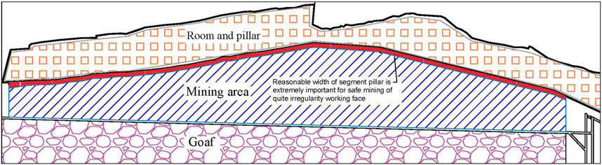
FIGURE 1. Quite irregularity left-over coal seam area.
Based on the characteristics of the working face, four preliminary layout schemes have been designed: regular layout, asymmetric handle (one-time expansion of the working face) layout scheme, symmetric handle (expansion-contraction) layout scheme, and extremely irregular (multiple expansion-contraction) layout scheme. As shown in Figure 2.
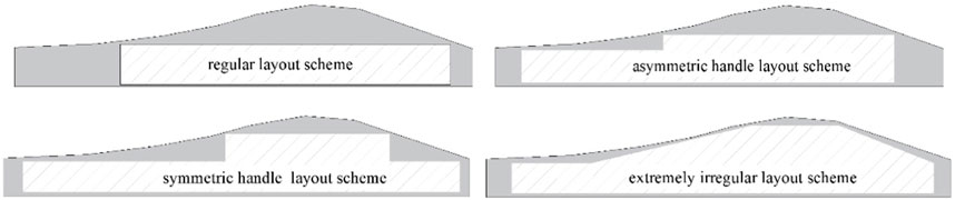
FIGURE 2. Different layout schemes of irregular working face.
Through economic and technical comparison, although the extremely irregular working face has some complicated processes and is difficult to mine, it can mine 438,400 tons more coal than the conventional regular layout, and the economic benefits are significant. Choose an extremely irregular layout as the mining plan for the A503 working face of Qiuzi Mine. The variation of working face length can be divided into areas with unchanged face length, areas with increased face length, and areas with decreased face length. Hydraulic support technology will be increased while hydraulic support technology will be decreased to complete the mining of quite erratic coal seams.
As is clear from this technique, an appropriate segment pillar width is crucial for the secure mining of relatively erratic working faces. The load on the pillar of coal is affected by mining the working face, and as variations in the working face’s forward motion occur, so does the mining width (Zhu et al., 2014; Gao et al., 2019). There will be a significant loss of coal resources in a relatively limited working face width if the coal pillars are left in place in compliance with the limit load. To ensure safe mining at the working face without losing significant resources available for coal, the coal’s dimensions and pillars should be modified together with the working face’s width.
The basic mechanical properties of coal samples are the basis for studying the reasonable size of coal pillars. The wider the coal pillar, the greater the compressive strength, but at the same time, the more coal resources are wasted. A reasonable width of coal pillars can not only meet the requirements of roadway protection but also reduce the waste of coal resources. Determining the strength of coal pillars with different aspect ratios is the key to determining the reasonable width of coal pillars. Because the height of the roadway is a fixed amount, the strength of coal pillars with different widths must be considered first when retaining coal pillars. In order to determine the strength of coal pillars with different aspect ratios, uniaxial compression tests (UCT) were carried out on coal samples with different aspect ratios.
From the Qiuci Coal Mine in Kuche, Xinjiang Province, China, coal samples were taken from whole coal. The samples were constructed in accordance with the experimental specification advised by ISRM and were cylindrical, as depicted in Figure 3, with a diameter of 50 mm and heights of 15, 20, 30, 35, 50, 75, and 100 mm. The tests were carried out. using electro-hydraulic servo rock testing equipment created by Changchun Corporation that has a maximum axial pressure of 1,000 kN.
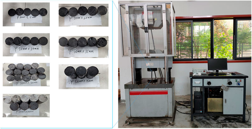
FIGURE 3. Tester and coal samples with different aspect ratios.
Using an ultrasonic detector RSM-SY5, the P-wave velocities of each coal sample were determined using an instrument with a timing precision of 0.05 μs, a test range of 0–629,000 μs, an amplifier power of 82 dB, and a bandwidth of 10 kHz–250 kHz. For testing, three coal samples for each ratio with P-wave velocities between 1,550 and 1,750 m/s were chosen. All measurements were carried out until the sample was destroyed at a 0.002 mm/s constant loading rate.
Coal samples’ stress-strain curves at various ratios under UCT are shown in Figures 4, 5.
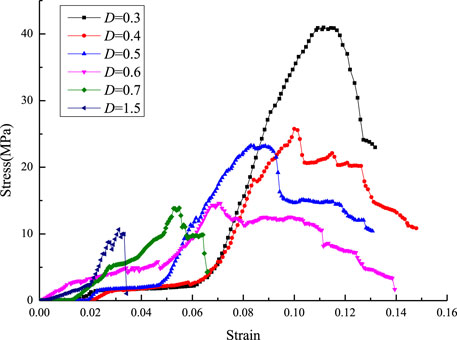
FIGURE 4. Coal samples’ stress-strain curves at various aspect ratios.
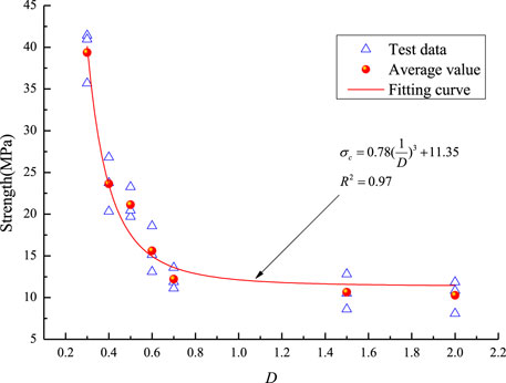
FIGURE 5. Coal samples strength with different aspect ratios (where D is aspect ratios).
It is depicted in Figure 3 based on the coal samples’ stress-strain curves, which show various proportions. It is clear that the compression stage, the linear elastic stage, the fracture propagation stage, the yield stage, and the post-peak stage can be distinguished in the stress-strain curves of coal samples with various proportions. The compression stage of the coal sample is shortened, and the elastic stage is prolonged with the increase in length-diameter ratio. The wider the coal sample, the greater the peak strength and the greater the residual strength.
Figure 4 shows that as the aspect ratio rises, the average durability of the coal samples decreases. The coal’s durability sample has the following relationship to D:
When D < 0.7, the strength of the coal sample increases greatly with the decrease in the height-diameter ratio.
The relationship between the height-diameter ratio and the compressive strength of coal samples was obtained by laboratory experiments. However, because the laboratory experiment is carried out on small-sized coal samples, it can only reflect the law of the influence of width on strength and cannot represent the strength of large-scale coal pillars. It is still necessary to construct the strength formula for the on-site coal pillar scales because the aspect ratio plays a significant role in the coal sample strength.
Small-scale specimens do not accurately reflect the strength and behaviour of coal bulk under stress and strain. Large-size coal specimens are therefore necessary for performing UCT. However, it is quite challenging to complete UCT on large-size specimens (JaiswalShrivastva, 2009b). A reliable strategy is the use of numerical simulation (MohanSheoreyKushwaha, 2001; ShabanimashcoolLi, 2012).
The pillar width between the roadway and room goaf is altered with the working face’s length once the very irregular working face is prepared. The layout of an appropriate coal pillar width is based on the strength of coal pillars with various aspect ratios (Jiang et al., 2011; Wang et al., 2011). Therefore, the strength of coal pillars with various aspect ratios was investigated using FLAC3D numerical simulation software. The model has a floor, pillar, and roof. Based on the dimensions of panel A503 from the Qiuci Coal Mine, four coal pillar numerical models were created, with a total width along the x, y, and z axes of 9 m, 14 m, 19 m, and 24 m, and a height in the z direction of 10 m. According to Figure 6, one zone’s coal pillar length is 0.1 m × 0.1 m × 0.1 m. To examine the strength of coal pillars with various aspect ratios, software was employed.
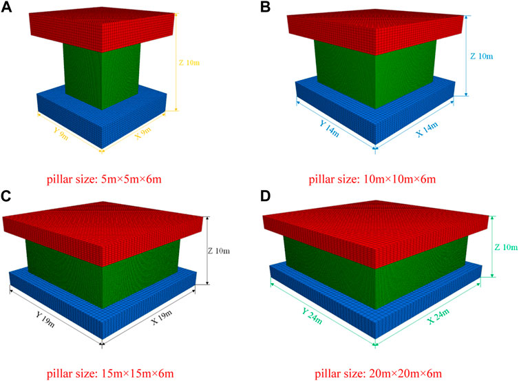
FIGURE 6. Models of pillars with different aspect ratios. (A) Pillar size: 5 m × 5 m × 6 m. (B) Pillar size: 10 m × 10 m × 6 m. (C) Pillar size: 15 m × 15 m × 6 m (D) Pillar size: 20 m × 20 m × 6 m.
The x, y, and z directions, as well as the model’s top, were set in the vertical direction to maintain a constant vertical velocity of displacement, which is confined to the roof and floor boundaries, respectively. The pillar is modelled using the Mohr Coulomb yield criterion with train softening (DuncanTruemanCraig, 1995).
Through experimental testing, the physical and mechanical characteristics of samples of ordinary coal were determined. The charcoal samples’ elastic moduli were 0.5 GPa, 10.7 MPa for uniaxial compressive strength, 0.27 for Poisson ratio, 5.3 MPa for cohesive strength, and 25.2° for friction, respectively. The carbon pillar’s plastic stress softening characteristics are represented in Table 1.
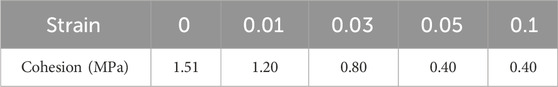
TABLE 1. Strain-softening plastic properties for coal pillar.
Figure 7 illustrates the curves of stress and strain, and failure traits of coal samples with various aspect ratios when using numerical simulation tools.
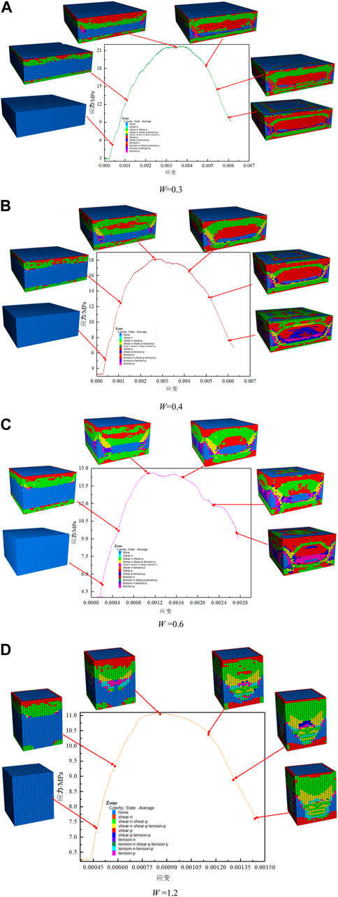
FIGURE 7. Failure characteristics and stress-strain curves of coal samples with various aspect ratios. (A) W=0.3. (B) W=0.4. (C) W =0.6. (D) W =1.2.
Figure 7 shows how the stress-strain curves of coal samples with different aspect ratios are similar to the shape of laboratory tests. It includes the post-peak stage, the yield stage, and the elastic stage. In the early stage of coal pillar deformation, the upper and lower boundaries first undergo compaction deformation and then extend to the middle of the coal sample. With the loading of pressure, the plastic zone expands, so that the column is less damaged in the elastic stage. The failure of the coal pillar is mainly a shear failure. Stress concentration occurs at the diagonal, so the diagonal is first destroyed. Both sides occur symmetrically. The coal pillar experienced shear failure of the X-shaped conjugate slope. The higher the D, the more obvious the shear failure characteristics of the double-inclined plane of the coal pillar.
The strength design formula suggested by Bieniawski (1992), Holland (Pati, 2011), Bunting, and Bunschinger is employed as the calculation formula for pillar strength in the mine. Table 2 displays the strength of coal pillars with various aspect ratios.
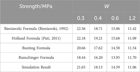
TABLE 2. Strength of coal pillars with different aspect ratios.
Figure 8 illustrates how the coal pillar’s strength decreases as W rises. The Bieniawski formula fits the results of the numerical model better than the other four strength formulas, which can roughly reflect the relationship’s trend. The right coal pillar strength formula in the Qiuci mine can be obtained by using the Bieniawski formula to correct the coal pillar strength.
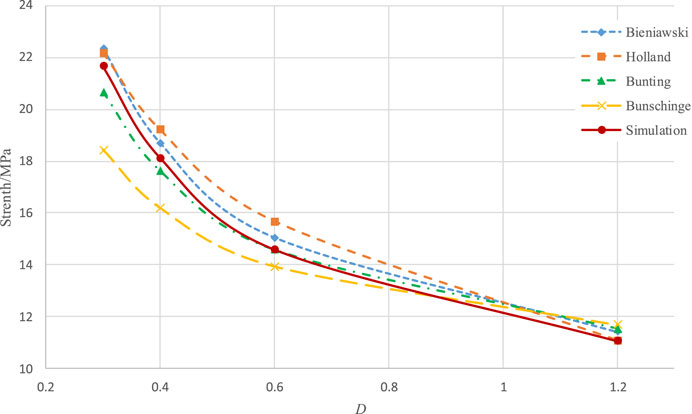
FIGURE 8. Pillar strength with different aspect ratios.
Figure 9 shows that the curve of the coal pillar’s adjusted strength and W agrees exactly with the outcomes of the numerical model, with a correlation degree of 1.
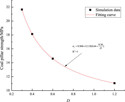
FIGURE 9. Pillar strength with different aspect ratios.
The roof can be reduced to a beam with a very erratic working face. The support of the coal pillar received below is simplified as the elastic foundation, and the weight of the rock formation above the beam is simplified as the load qc. The roof mechanical model is constructed, and the two sides of the beam are fixed, as shown in Figure 10.
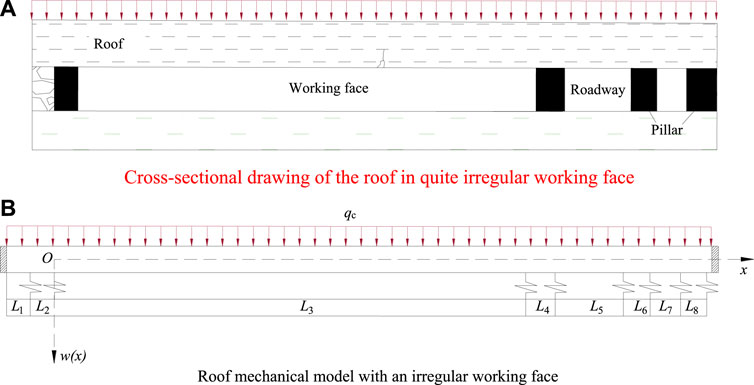
FIGURE 10. A simplified roof model with a quite irregular working face. (A) Cross-sectional drawing of the roof in quite irregular working face. (B) Roof mechanical model with an irregular working face.
The differential equation for the beam’s curved surface is:
The cross-sectional moment of inertia of the beam is I, m4, and the elastic modulus of the beam is E, GPa. The load received below the beam is represented by P(x), and the load received above the beam is represented by q(x).
The foundation’s reaction force for an elastic foundation can be expressed as follows:
When L3<x≤ L3 + L4, taking the characteristic coefficient
Similarly, the general solution of other area elastic foundation equation can also be obtained.
When 0<x≤ L3, the general answer to Eq. 3 is as follows Huang et al. (2020):
The corner’s relationship to the bending moment, shear force, and deflection of a particular segment of the beam is as follows Huang et al. (2020):
Both ends of the beam are fixed ends, so the boundary condition is:
Additionally, the bending, shear, corner, and deflection moments are equivalent at x = –L2, x = 0, x = L3, x = L3 + L4, x = L3 + L4+ L5, x = L3 + L4+ L5+ L6, x = L3 + L4+ L5+ L6 + L7 in the model. From the above boundary conditions, unknown coefficients can be determined.
The tension of the coal pillars in the regional domain can be determined using Eq. 4 in place of Eq. 8 to model the region of the coal pillars as a continuously distributed Winkler elastic foundation Zhang et al. (2017):
The stress in a single coal pillar will be the integration for stress in this range of area, such as: Assuming that the length and width of the coal room make up the range of coordinates in the load-bearing area of a single coal pillar, [x1, x2], the stress in the single coal pillar will be Zhang et al. (2017):
Equation 10, when integrated, yields the single coal pillar’s stress as:
The foundation coefficient k0 is 8×10⁹, the overlaying uniform load qc is 3.2 × 10⁶ N/m2, the basic top elastic modulus E is 20.9 GPa, and the fundamental thickness of the A5 coal seam is 11 m, according to the Qiuci Mine’s geological information. Roadway widths in the A503 working face L5 are 4 m, coal pillar widths in the A503 working face L2 are 6 m, room-pillar goaf widths in L6 and L8, mining width in L7 is 5 m, and the length of the suspended roof in the A502 working face L1 is 10 m. The concentration factor (k) is 2. The link between the working face length and coal pillar strength by bringing these parameters into Eq. 11 is shown in Figure 11.
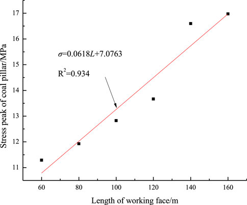
FIGURE 11. Relationship between the working face length and the pillar of coal strength.
As seen in Figure 10, the coal pillar’s peak tension rises as the face length of the working face lengthens. The following equation determines the face length and peak stress of the pillar created by fitting:
The proportion of the length of the working face and the aspect ratio can be determined as follows by combining formulas (2) and (12):
The breadth of coal pillars varies as a result of the A503 working face of Qiuci Mine adopting a very atypical arrangement to extract as many coal resources as possible. The surface length of each area is entered into formula (13), and the theoretical working face’s length and the minimal width of the pillar of coal are calculated as shown in Figure 12 in the instance where the height of the pillar of coal is h = 6 m.
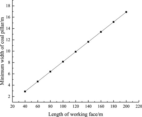
FIGURE 12. Theoretical length of working face and the minimum width of pillar of coal.
The alteration in face length is primarily divided into four sections in the actual manufacturing process: the beginning working face, whose length is constant; the length rising working face; the length constant working face in the intermediate area; and the length dropping working face. The length increase working face has a minimum coal pillar in width 13.4 m, the length constant working face has a minimum coal pillar in width 13.4 m, and the length decrease working face has a minimum coal pillar in width from 3.68 m to 13.4 m, according to formula (12) and Figure 12. The coal pillar’s smallest width is 4.91 m in the initial face. As a result, Figure 13 depicts the theoretical border of the actual coal pillar and the minimum coal pillar width boundary line.
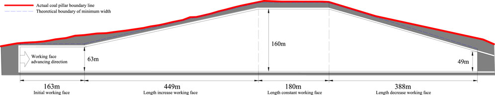
FIGURE 13. Theoretical boundary of minimum size of the coal pillar, and actual pillar of coal boundary line.
Figure 13 indicates that the theoretical limit of the smallest width of the coal pillar is within the bounds of the actual coal pillar boundary line.
From June 5 to July 10, during the mining of A503 working face, the deformation of the top of the roadway was observed. The displacement monitoring of the roadway roof is carried out. The deformation monitoring station is set every 30 m in the middle of the track roadway of the A503 working face, and a total of 7 stations are arranged. The deformation of roadway roof was monitored by LBY-3 double anchor roof separation instrument. The layout of the station is shown in Figure 14. Figure 15 shows the deformation of the top of the roadway at station 1 and station 7.
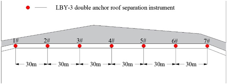
FIGURE 14. Location of measurement station layout.
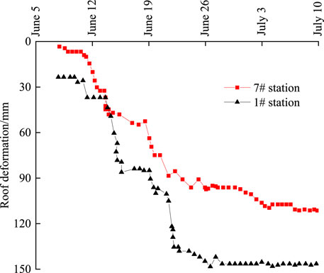
FIGURE 15. Deformation law of the roadway at the 1# and 7# stations.
Figure 15 illustrates how the deformation of the roadway roof advances along with the working face and eventually tends to a steady value. There is no abrupt shift in the roadway’s sinking and deformation process, indicating that there has not been any damage to the roof, like a roof fall. Neither the roadway’s roof nor its walls experienced any phenomena like the roof collapsing or peeling, and neither did the roadway’s supporting structure fall off or sustain significant deformation or other damage. It demonstrates how reasonable and capable the coal pillars in the road are for maintaining safe mining on the working face of A503.
Following a thorough investigation of the suitable coal pillar width that fluctuates with the size of the atypical working face, the following precise results were drawn:
(1) Seven coal samples with varying aspect ratios had their uniaxial compressive strengths measured, and it was discovered that there was an inverse link between the two. The coal pillars’ failure characteristics are examined primarily for shear failure using four numerical compression models of coal pillars with aspect ratios. The coal pillar’s formula for strength is
(2) A mechanical roof model with a quite erratic working face was constructed, and the coal pillar’s stress was measured. The length of the working face and the aspect ratio of the coal pillar were calculated using the coal pillar strength formula, and it was found that when the working face length grows, the appropriate breadth of the coal pillar must likewise increase.
(3) The suitable width of the highway of the A503 Qiuci Coal Mine’s working face is constructed in accordance with the relationship between the working face’s length and the width of the coal pillar. Monitoring of the roadway’s roof subsidence on-site reveals that there is no evidence of roof caving or sheeting, and the roadway’s maximum deformation is 147.3 mm.
The original contributions presented in the study are included in the article/supplementary material, further inquiries can be directed to the corresponding authors.
PH: Writing–original draft, Conceptualization, Writing–review and editing. QaZ: Conceptualization, Writing–review and editing. JX: Writing–review and editing. JL: Writing–review and editing. QiZ: Data curation, Writing–review and editing. ML: Formal Analysis, Writing–review and editing. FC: Methodology, Writing–review and editing.
The author(s) declare financial support was received for the research, authorship, and/or publication of this article. This research was funded by the National Natural Science Foundation of China (52104105), the Natural Science Foundation of Jiangsu Province (No. BK20210499) and Key Laboratory of Deep Earth Science and Engineering (Sichuan University), Ministry of Education (DESE202203).
The authors declare that the research was conducted in the absence of any commercial or financial relationships that could be construed as a potential conflict of interest.
All claims expressed in this article are solely those of the authors and do not necessarily represent those of their affiliated organizations, or those of the publisher, the editors and the reviewers. Any product that may be evaluated in this article, or claim that may be made by its manufacturer, is not guaranteed or endorsed by the publisher.
Bazant, Z. P., and Planas, J. (1997). Fracture and size effect in concrete and other quasibrittle materials. Vol. 16. Florida, United States: CRC Press. doi:10.1201/9780203756799
Bieniawski, Z. (1968). “The effect of specimen size on compressive strength of coal,” in International journal of rock mechanics and mining sciences & geomechanics abstracts (Amsterdam, Netherlands: Elsevier). doi:10.1016/0148-9062(68)90004-1
Bieniawski, Z. T. (1992). A method revisited: coal pillar strength formula based on field investigations. Available at: https://www.researchgate.net/publication/306200391_A_method_revisited_Coal_pillar_strength_formula_based_on_field_investigations.
ChughPulaPytel, Y. P. O. W. M. (1990). Ultimate bearing capacity and settlement of coal pillar sub-strata. Int. J. Min. Geol. Eng. 8 (2), 111–130. doi:10.1007/BF00920499
DuncanTruemanCraig, F. MERM S. (1995). Two- and three-dimensional elasto-plastic analysis for coal pillar design and its application to highwall mining. Int. J. Rock Mech. Min. Sci. Geomechanics Abstr. 32 (3), 215–225. doi:10.1016/0148-9062(94)00045-5
Fairhurst, C. E., and Hudson, J. A. (1999). Draft ISRM suggested method for the complete stress-strain curve for intact rock in uniaxial compression. Int. J. Rock Mech. Min. Sci. Geomechanics Abstr. 36 (3), 281–289. doi:10.1016/S0148-9062(99)00006-6
Gao, R., Yu, B., and Meng, X. B. (2019). Stress distribution and surrounding rock control of mining near to the overlying coal pillar in the working face. Int. J. Min. Sci. Technol. 29 (6), 881–887. doi:10.1016/j.ijmst.2018.07.003
He, W. R., He, F. L., and Zhao, Y. (2020). Field and simulation study of the rational coal pillar width in extra-thick coal seams. Energy Sci. Eng. 8 (3), 627–646. doi:10.1002/ese3.538
Huang, P., Zhang, J. X., Zhang, Q., Damascene, N. J., and Guo, Y. M. (2020). Nonlinear creep model of deep gangue backfilling material and time-dependent characteristics of roof deformation in backfilling mining. Geofluids. doi:10.1155/2020/8816871
Huang, P., Zhang, J. X., Yan, X. J., Spearing, A. J. S., Li, M., and Liu, S. W. (2021). Deformation response of roof in solid backfilling coal mining based on viscoelastic properties of waste gangue. Int. J. Min. Sci. Technol. 31 (2), 279–289. doi:10.1016/j.ijmst.2021.01.004
Hustrulid, W. (1976). A review of coal pillar strength formulas. Rock Mech. 8 (2), 115–145. doi:10.1007/BF01239762
JaiswalShrivastva, A. B. (2009a). Numerical simulation of coal pillar strength. Int. J. Rock Mech. Min. Sci. 46 (4), 779–788. doi:10.1016/j.ijrmms.2008.11.003
JaiswalShrivastva, A. B. K. (2009b). Numerical simulation of coal pillar strength. Int. J. Rock Mech. Min. Sci. 46 (4), 779–788. doi:10.1016/j.ijrmms.2008.11.003
Jiang, Y. D., Wang, H. W., Zhao, Y. X., Zhu, J., and Pang, X. F. (2011). The influence of roadway backfill on bursting liability and strength of coal pillar by numerical investigation. Ismsse 26, 2011. doi:10.1016/j.proeng.2011.11.2283
Khair, A., and Achanti, V. (1996). Effect of specimen size on compressive strength of coal. Golden, CO (United States): Colorado School of Mines.
KosteckiSpearing, T. A. (2015). Influence of backfill on coal pillar strength and floor bearing capacity in weak floor conditions in the Illinois Basin. Int. J. rock Mech. Min. Sci. 76, 55–67. doi:10.1016/j.ijrmms.2014.11.011
Li, B., Wang, G. H., Jia, C. Q., Ren, J., Lu, G. F., Liu, N. N., et al. (2021). A modified elastic foundation beam method for analyzing lateral wall deformation in excavations with cross wall. Adv. Civ. Eng. 2021, 1–16. doi:10.1155/2021/8838489
Li, C. L. (2006). Rock support design based on the concept of pressure arch. Int. J. Rock Mech. Min. Sci. 43 (7), 1083–1090. doi:10.1016/j.ijrmms.2006.02.007
Li, J. (2020). The coal pillar design method for a deep mining roadway based on the shape of the plastic zone in surrounding rocks. Arabian J. Geosciences 13 (12), 454. doi:10.1007/s12517-020-05501-9
MasoumiSaydamHagan, H. S. P. C. (2016). Unified size-effect law for intact rock. Int. J. Geomechanics 16 (2), 04015059. doi:10.1061/(asce)gm.1943-5622.0000543
Mohan, G. M., and SheoreyKushwaha, P. A. (2001). Numerical estimation of pillar strength in coal mines. Int. J. Rock Mech. Min. Sci. 38 (8), 1185–1192. doi:10.1016/S1365-1609(01)00071-5
MohanSheoreyKushwaha, G. M. P. R. A. (2001). Numerical estimation of pillar strength in coal mines. Int. J. Rock Mech. Min. Sci. 38 (8), 1185–1192. doi:10.1016/S1365-1609(01)00071-5
Pati, N. K. (2011). Evaluation of underground coal pillar design. Available at: http://ethesis.nitrkl.ac.in/2510/1/107MN015.pdf.
ShabanimashcoolLi, M. C. C. (2012). Numerical modelling of longwall mining and stability analysis of the gates in a coal mine. Int. J. Rock Mech. Min. Sci. 51, 24–34. none. doi:10.1016/j.ijrmms.2012.02.002
Wang, F. T., and Zhang, C. (2019). Reasonable coal pillar design and remote control mining technology for highwall residual coal resources. R. Soc. Open Sci. 6 (4), 181817. doi:10.1098/rsos.181817
Wang, H. W., Jiang, Y. D., Zhao, Y. X., Zhu, J., and Liu, S. (2013). Numerical investigation of the dynamic mechanical state of a coal pillar during longwall mining panel extraction. Rock Mech. rock Eng. 46 (5), 1211–1221. doi:10.1007/s00603-012-0337-8
Wang, H. W., Poulsen, B. A., Shen, B. T., Sheng, X., and Jiang, Y. D. (2011). The influence of roadway backfill on the coal pillar strength by numerical investigation. Int. J. Rock Mech. Min. Sci. 48 (3), 443–450. doi:10.1016/j.ijrmms.2010.09.007
Xiao, T. Q., Bai, J. B., Xu, L., and Zhang, X. B. (2011). Characteristics of stress distribution in floor strata and control of roadway stability under coal pillars. Min. Sci. Technol. (China) 21 (2), 243–247. doi:10.1016/j.mstc.2011.02.016
Yang, J. P., Cao, S. G., and Li, X. H. (2013). Failure laws of narrow pillar and asymmetric control technique of gob-side entry driving in island coal face. Int. J. Min. Sci. Technol. 23 (2), 267–272. doi:10.1016/j.ijmst.2013.04.008
Yang, R. S., Zhu, Y., Li, Y. L., Li, W. Y., and Lin, H. (2020). Coal pillar size design and surrounding rock control techniques in deep longwall entry. Arabian J. Geosciences 13 (12), 453. doi:10.1007/s12517-020-05454-z
Yu, Y. X., and HuangWang, RBBQ (2016). Analysis on limit equilibrium zone of coal pillar in mining roadway based on mechanical model of elastic foundation beam. J. Eng. Mech. 142 (4), 04016009. doi:10.1061/(asce)em.1943-7889.0001032
Zhang, J. W., Wang, H. L., and Chen, S. J. (2018). Bearing capacity of backfill body and roof stability during strip coal pillar extracted with paste backfill. Geotechnical Geol. Eng. 36 (1), 235–245. doi:10.1007/s10706-017-0322-9
Zhang, Y. J., Feng, G. R., Zhang, M., Ren, H. R., Bai, J. W., Guo, Y. X., et al. (2016). Residual coal exploitation and its impact on sustainable development of the coal industry in China. Energy Policy 96, 534–541. doi:10.1016/j.enpol.2016.06.033
Zhang, J. X., Huang, P., Huang, P., Li, M., and Chen, Z. W. (2017). Stability and control of room mining coal pillars—taking room mining coal pillars of solid backfill recovery as an example. J. Cent. South Univ. 24 (05), 1121–1132. doi:10.1007/s11771-017-3515-8
Keywords: pillar strength, multiscale study, reasonable width, left-over coal, failure of coal pillar
Citation: Huang P, Zhang Q, Xie J, Li J, Zhang Q, Li M and Simao FC (2024) Multiscale study on coal pillar strength and rational size under variable width working face. Front. Environ. Sci. 12:1338642. doi: 10.3389/fenvs.2024.1338642
Received: 15 November 2023; Accepted: 15 January 2024;
Published: 29 January 2024.
Edited by:
Cun Zhang, China University of Mining and Technology, Beijing, ChinaReviewed by:
Shengrong Xie, China University of Mining and Technology, Beijing, ChinaCopyright © 2024 Huang, Zhang, Xie, Li, Zhang, Li and Simao. This is an open-access article distributed under the terms of the Creative Commons Attribution License (CC BY). The use, distribution or reproduction in other forums is permitted, provided the original author(s) and the copyright owner(s) are credited and that the original publication in this journal is cited, in accordance with accepted academic practice. No use, distribution or reproduction is permitted which does not comply with these terms.
*Correspondence: Jing Xie, eGllamluZzIwMDY1NUAxNjMuY29t; Junmeng Li, bGlqdW5tZW5nMTIwMUBjdW10LmVkdS5jbg==
Disclaimer: All claims expressed in this article are solely those of the authors and do not necessarily represent those of their affiliated organizations, or those of the publisher, the editors and the reviewers. Any product that may be evaluated in this article or claim that may be made by its manufacturer is not guaranteed or endorsed by the publisher.
Research integrity at Frontiers
Learn more about the work of our research integrity team to safeguard the quality of each article we publish.