 Tao Jiang1
 Pengliang Yang
95% of researchers rate our articles as excellent or good
Learn more about the work of our research integrity team to safeguard the quality of each article we publish.
Find out more
ORIGINAL RESEARCH article
Front. Environ. Sci. , 29 September 2023
Sec. Environmental Informatics and Remote Sensing
Volume 11 - 2023 | https://doi.org/10.3389/fenvs.2023.1251664
This article is part of the Research Topic Spatial Modelling and Failure Analysis of Natural and Engineering Disasters through Data-Based Methods,volume III View all 18 articles
To solve the problem of fracturing due to high water pressure when pumping in the diversion tunnel, the mechanism of hydraulic fracturing (HF) in the tunnel under high internal water pressure is studied. A numerical model of HF considering water-rock interaction is established using the PFC2D discrete element simulation software. The HF mechanism of surrounding rock under high internal water pressure is studied, and the development process of hydraulic cracks is obtained. The influence of surrounding rock parameters on fracturing is analyzed and the law between principal stress and crack development is investigated. The high-pressure water injection test under different tunnel diameters is also carried out. Numerical test research shows that under the action of high internal water pressure, the surrounding rock at the cavity wall splits first, and the water entering the crack generates water pressure on the crack sidewall, which in turn generates tensile stress at the crack tip and further causes the crack expansion. The crack length is exponentially related to the internal water pressure. The high internal water pressure decays gradually with the crack extension distance and stabilizes when the crack extension reaches a certain length because the water pressure is less than the tensile strength of the surrounding rock. The fracturing results indicate that the process of HF damage is tensile types, and the increase of cohesion plays a suppressive role in crack opening, while the internal friction angle has little effect on the HF effect. The influence of principal stress on the HF result shows that the direction of HF is along the direction of major principal stress. The major principal stress promotes the cracking, while the minor principal stress inhibits the crack growth. By simulating the water injection test for different hole diameters of the diversion tunnel, it is found that the fracturing distance of the surrounding rock increases approximately linearly with the increase of the hole diameter. The test results can provide a basis for the design and construction of high-pressure tunnels such as pumped storage power plants.
Hydraulic fracturing (HF) is a physical phenomenon that causes cracks and expansion in rock or soil due to the elevation of fluid pressure. The hydraulic fracturing is more common in underground engineering. It has been used in gas field extraction as early as the 1940s (Britt, 2012; Damjanac and Cundall, 2016). In the field of geothermal power generation, hydraulic fracturing is an important method to obtain geothermal energy by controlling the direction and degree of fracture development. Creating fractures in the hot rock and injecting low-temperature water along the fractures can obtain thermal energy underground (Legarth et al., 2005; Ghassemi et al., 2007). Through hydraulic fracturing, the injection of fluid can capture geothermal heat over a larger area (Zimmermann et al., 2011). In addition, hydraulic fracturing behavior is important in areas such as environmental protection (Murdoch and Slack, 2002; Goodman et al., 2016) and magma flow (Lister et al., 1991). However, in some areas, hydraulic fracturing can be harmful, such as in water diversion tunnels where hydraulic fracturing can damage the tunnel structure, and in dam foundations where hydraulic fracturing can cause water seepage or instability, with serious engineering consequences (Zhao et al., 2022; Zhu et al., 2022). It has become crucial to understand the mechanism of hydraulic fracturing and find solutions to the risks brought on by hydraulic fracturing as a result of the recent development of large water conservation projects.
At present, the research methods of rock hydraulic fracturing mainly include laboratory model tests (Shearing or compression tests, uniaxial and triaxial compression tests), theoretical analysis (Blanton’s criterion, Warpinski and Teufel’s criterion, Renshaw and Pollard’s criterion, etc.) and numerical simulations (The continuous, discontinuous and hybrid continuum-discrete method) (Lin et al., 2022; Lei et al., 2023; Lin et al., 2023; Guo et al., 2014). studied the effects of stress, flow rate, and fracturing fluid viscosity on fracture extension patterns based on large triaxial tests. (Patel et al., 2017). conducted triaxial tests of hydraulic fracturing to study the effect of cyclic pressure on the destructive force of rock masses. (Tan et al., 2017). conducted true triaxial hydraulic fracturing experiments in layered shales to understand the fracture initiation and vertical extension behavior. He also summarized four typical modes of fracture extension in shale formations from the physical experiment results. (Li et al., 2020). developed a mathematical model for hydraulic fracturing to predict fracture parameters. The results showed that field stress plays a major role in the development of cracks, the fracture toughness of the rock can inhibit the growth of fractures, and the fracture fluid density promotes the expansion of fractures. (Chukwudozie et al., 2019; Lin et al., 2022). derived a unified fracture-porous media hydraulic fracturing model based on the energy criterion of Griffith theory and used the variational phase field method to deal with the interaction of multiple fractures and their evolution along complex paths. Lecampion and Detournay (Lecampion and Detournay, 2007) developed an implicit moving grid algorithm to solve the plane strain propagation problem for hydraulic fracturing. This algorithm is well suited for plane strain hydraulic fracturing problems with hysteresis.
Numerical simulation can better obtain the process of hydraulic fracturing and study the mechanism than model tests. Numerical hydraulic fracturing models are divided into coupled and uncoupled models. The coupled model considers the interaction between water and surrounding rock (Zhang et al., 2017; Huang et al., 2020; Lei et al., 2020; Jia et al., 2021) while the uncoupled model ignore such interaction (Shimizu et al., 2011). studied the effect of fluid viscosity on fracture initiation pressure, and they found that low-viscosity fluids are more likely to penetrate into the fracture and apply fluid pressure to the entire fracture surface. Therefore, the fracture pressure of low-viscosity fluids is lower than that of high-viscosity fluids. (Wang et al., 2009). used realistic failure process analysis (F-RFPA2D) to study the emergence and expansion behavior of fractures in hard soils during injection, and investigated the effect of soil homogeneity on the fractured ground. (Li et al., 2012). developed a parallel finite element program, RFPA3D-Parallel, for stress and seepage field analysis. The program considers the coupled effects of seepage, damage, and stress fields to model progressive damage and associated fluid flow in rocks in three dimensions. The program can be used to study the hydrodynamic response of laboratory-scale rock samples (Ren et al., 2009). use extended finite element method (XFEM) for numerical simulation of hydraulic fracturing. XFEM can overcome the disadvantages of classical finite elements, such as no dense mesh near the fracture and no need to set the path of the fracture. The pre-processing work is greatly simplified. (Zhou and Hou, 2013; Zhao et al., 2021). used fast lagrangian analysis of continua in 3 dimensions (FLAC3D) to study the mechanical behavior of rock formations based on continuous media mechanics. The simulation considers the crack extension in the geometric model and the hydrodynamic coupling effect between the crack and the matrix in the three-dimensional stress state. A finite-discrete element method (FDEM)-based coupled hydrodynamic model is proposed by (Yan et al., 2016), where each complete object is discretized with a mesh consisting of 3-node triangular elements, and joint cells with no initial thickness are inserted at the common edges of the triangular cells for simulating hydraulic fracturing with complex fracture geometries. The proposed hydraulic fracture network update algorithm can accurately update the most complex hydraulic fracture network during the hydraulic fracturing process. However, finite element method (FEM) or XFEM requires huge computational costs, and it is difficult to study fracture extension due to its limitations on grid orientation, numerical discretization, and especially fracture extension direction. The boundary element method can use fewer elements with the same accuracy and high computational efficiency. (Zhou et al., 2016). developed a numerical model using the maximum circumferential (MCS) theory and the boundary element method (BEM) to study the effects of single and combined factors and proposed an evaluation factor to evaluate the direction of fracture extension. The discrete element method can simulate large deformation problems in rock masses more simply and realistically than the frequent mesh division of traditional finite element simulation methods. (Damjanac et al., 2016). developed the 'SRM' model using the bonded particle model (BPM) and synthetic rock mass (SRM) concepts to overcome the limitations of the original discrete element method (DEM) model that required predefined fracture trajectories. (McClure et al., 2016). developed a hydraulic fracturing simulator that describes the expansion of hydraulic fractures as well as simulates the tensioning and shearing of natural fractures based on stress states. (Wang et al., 2014) used the granular flow method to design several parameter combinations to study the effects of macroscopic parameters and initial stresses of the coal seam on the cleavage state, and found that the fracture radius was mainly affected by the deformation parameters. These scholars have made great contributions to the research and application of hydraulic fracturing. The hydraulic fracturing process is accompanied by the interaction between water flow within the fracture and fracture expansion, and it is important to construct a suitable hydraulic coupling model to simulate the real hydraulic splitting process, and it can be found that there are still relatively few studies on the influence parameters of hydraulic splitting in the coupled state. Most of the previous tests have used lower pressures for hydraulic splitting, and there is less research on hydraulic fracturing under high internal water pressure. In recent years, a large number of pumped storage power plants have been built in China, with the highest head reaching 800 m. It is of great practical significance to carry out research on the mechanism of hydraulic fracturing under high internal water pressure.
The paper uses discrete element method (DEM) to establish a hydraulic fracturing model of hydraulic coupling from ameso-scale mechanical approach for the previous situation where the coupling of water-rock interaction is less considered. The mechanism of hydraulic fracturing in the tunnel surrounding rock under high internal water pressure is studied. The influence of major principal stresses in the formation on the direction of fracture development under high internal water pressure is initially explored, and the influence of formation parameters on the development of hydraulic fracturing is investigated. The research results can provide a reference for the design and construction of hydraulic tunnel engineering under consideration of high internal water pressure.
The calculation between fluid and particle cells are performed in the particle flow code (PFC) by differential methods, and the connection is established by the forces acting on the fluid and the particles. Changes in fluid volume in the pores cause variation of the forces acting on the particles, which in turn affect the volume of fluid between the particles after the forces are applied. The solid-liquid coupling process is shown in Figure 1 (Zimmerman and Bodvarsson, 1996; Al-Busaidi et al., 2005), where the particle medium is studied from the meso-scale using the discrete medium approach, and the pore fluid is considered at the mesoscale level based on the continuous medium approach for its average value.

FIGURE 1. Schematic diagram of the fluid-solid coupling process in PFC.
In the particle flow simulation, the fluid flow is simulated by introducing fluid “domains” and fluid "ducts” (Itasca’s Particle Flow Code, 2008). As shown in Figure 2, the “domains” are used to store the fluid, each domain is enclosed by a closed particle contact, and the “pipes” are the channels for fluid flow. The mechanical response causes a change of the “pipe” to achieve a change in the flow rate, which in turn causes a change in the pressure in the domain, and then the fluid pressure acts on the particles, thus realizing the hydraulic coupling effect.
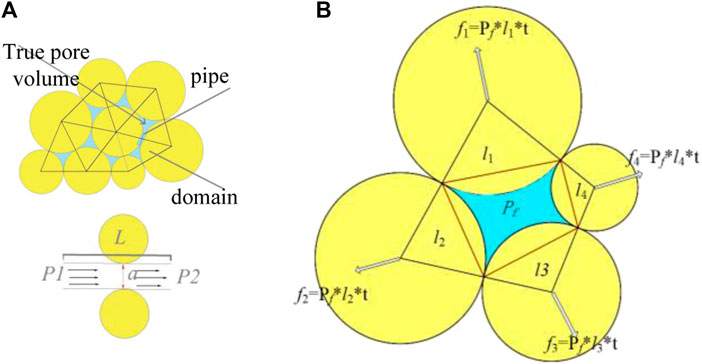
FIGURE 2. Pipe domain model in DEM. (A) Schematic diagram of the percolation model between bonded particles; (B) Particle stress vector calculation diagram.
In the process of hydraulic fracturing, because of its low velocity and conforms to the laminar flow condition, the flow rate q in the pipeline can be calculated according to the cubic theorem of parallel plate seepage.
where, µ is the dynamic viscosity coefficient of the fluid, and Pl, P2 is the pressure in the fluid domain at both ends of the pipe.
Assuming that the fluid flow follows the Poiseuille law, the flow rate can be written as:
where, q is the flow rate (m3/s); a is the hydraulic aperture, which is related to the normal force of the two particles; k is the permeability coefficient; and L is the pipe length;
From Eq. 2, it can be seen that the opening a will affect the flow of the pipeline, that is, the permeability of the model. The influence of the mechanical process on the fluid flow is mainly reflected in that the mechanical process determines the opening of the pore channel, and the change of the opening affects the fluid flow rate. The influence of fluid on mechanical processes is mainly manifested in the fluctuation of pore fluid pressure caused by fluid flow, the pore fluid pressure acting on particles and the viscous force during fluid flow.
At the contact point between particles, it is assumed that there is an initial opening. The existence of the initial opening allows fluid flow in the fluid channel formed by the two particles even when they are in close contact, thus ensuring the matrix permeability of the material. The opening a of the fluid channel depends on the contact force between particles. When the normal contact force between two particles is compressive stress, the opening a of the fluid channel is calculated by the following formula:
where, F is the current compression force between the two particles, and F0 is the compression force when the pipe opening is reduced to half of the initial opening.
From Eq. 4, it can be seen that when the compression force between particles increases, the opening of the pipeline will decrease; when the compression force between particles decreases, the opening of the pipeline will increase. The hydraulic coupling effect is achieved through the relationship between this force and the fluid channel.
When two cemented particles are in tension, or the bond between the two particles has been destroyed, and the particles are disconnected at the contact point, the opening a is calculated by the following formula:
where, d is the distance between the two particles, and R1, R2 are the radii of the two particles respectively, and
In time steps
Where,
In order to simplify the problem of introducing water pressure into particles, it is assumed that the pressure change due to the flow of fluid in the pipe occurs only within the corresponding contact, that the stress is uniform in each individual domain, and that the push force is connected to other Domain is irrelevant. If around a domain, the path connecting the contacts is polygonal, the stress vector on the particle is:
where, f is the normal unit vector of the line connecting the two contact points; t is the length of the line.
The condition to ensure the stability of the model operation is that the pressure change due to water inflow must be smaller than the disturbance pressure, and the critical time step
where, N is the number of pipes connected to a “domain”; and r is the average radius of the particles around a “domain”.
All constant parameter values as follows: a0: 8.6e-6, F0: 1e10, λ: 0.1, Kf: 2.18e9. To ensure stability over the entire computational domain, the overall time step must be the minimum of all local time steps, in addition to being multiplied by a safety factor of less than 1.0.
Considering the engineering geological conditions of a typical tunnel for pumped-storage power station, a discrete element numerical model of circular tunnel is established. Considering the limited computational capability of PFC2D, the surrounding rock within a certain range around the center of the tunnel is selected for establishing the model. As shown in Figure 3, the model size is 30 m × 30 m, the inner model particle (earth yellow) size is between 0.08 m and 0.12 m, and the outer model particle size (light brown) is between 0.12 m and 0.18 m. The tunnel center is located in the center of the model and the tunnel diameter is 6 m. The tunnel is excavated with full section tunnel method. The size of the model is about 6 times of the diameter of the tunnel. It is large enough to ignore the tunnelling on the boundary. Since the acceleration due to gravity is small compared to the overlying pressure, it is not considered in the calculation.
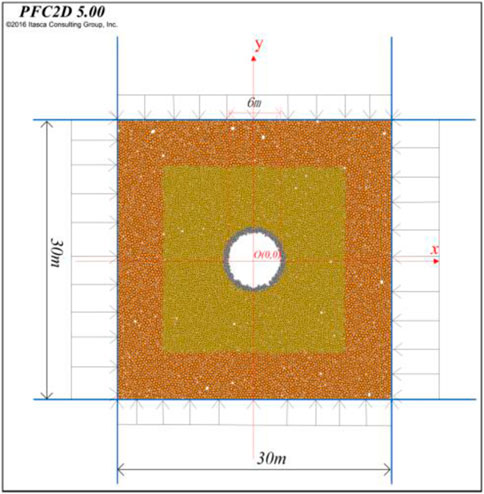
FIGURE 3. Numerical model with DEM.
In order to simulate the flow of fluid in rock mass, track the process of crack initiation and propagation directly, and study the mechanism of hydraulic fracturing in rock mass, the hydraulic coupling calculation is used. In the hydraulic coupling calculation, it is necessary to establish the fluid pipe domain model of the surrounding rock. Figure 4 shows the fluid pipe domain model after tunnel excavation. The center point of the model is the water filling point of the high-pressure tunnel.
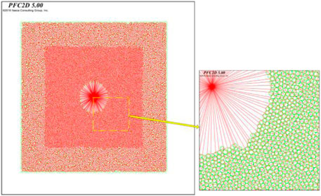
FIGURE 4. Hydrodynamically coupled fluid pipe domain model.
The pipe-domain model considers the water-rock coupling, which means the relationship between the crack development and the distribution or flow of water in rock mass under the action of water pressure. The model can simulate the flow state of water in rock more truly and can not only describe the fluid phase and the solid phase accurately, but also combine the numerical method of mesh division with the particle discrete element method. It also saves a lot of computing costs. The difference between dynamic and static internal water pressure may indeed have an effect on hydraulic fracturing results. Dynamic internal water pressure refers to the fluctuation of water pressure with time and force during hydraulic fracturing. This dynamically fluctuating internal water pressure may affect the rock’s fracture pattern and splitting effectiveness. On the one hand, higher dynamic internal water pressure may lead to stronger hydraulic shock force, which increases the resistance and damage degree of rock. This can make the rock more difficult to split or achieve the desired splitting effect. On the other hand, fluctuations in dynamic internal water pressure may also cause rocks impacted by water pressure to be acted on by different forces at different times or locations, thus having an uneven impact on the fracture path and the formed cracks. This can lead to changes in the rock’s fracture pattern, with possible additional fractures, offsets, or changes in fracture direction. Therefore, in order to obtain a more stable splitting effect, it is important to keep a relatively stable internal water pressure as much as possible. Minimizing fluctuations in internal water pressure by controlling the parameters and operation of the hydraulic system helps to improve the consistency and predictability of hydraulic splitting.
The fluid-solid coupling is realized by the following ways. 1) The size of the pipe is determined by the contact force between particles and the change of piper size will cause the change of particle contact force, so as to realize the coupling between the seepage of the model and the stress state. 2) The forces acting on the particle change the volume of the domain which in turn influence the pressure inside the domain. 3) The pressure difference between adjacent domains acts on the surrounding particles in the form of seepage volume force. Therefore, the influence of seepage on the stress state of solid particles is considered.
Field stress is applied by the action of the 'wall' (the blue border in Figure 3) on the particles. According to the field stress test results obtained by the stress relief method in the field, the high-pressure tunnel construction area is dominated by horizontal stress. Therefore, in the two-dimensional numerical model, the horizontal direction is selected as major principal stress direction, and the vertical direction is selected as the minor principal stress direction. The determined horizontal stress
According to the regional geological report of the tunnel, the parameters of the surrounding rock are shown in Table 1.
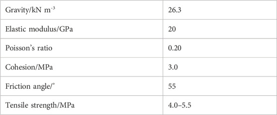
TABLE 1. Physical and mechanical parameters of surrounding rock.
In particle flow code, the macroscopic response of the material is inferred from the interactions of microscopic properties. The purpose of microscale parameter calibration is to obtain unknown parameters of particles and bonds in DEM calculations (Yu et al., 2021). Since the relationship between the input microscale parameters and the target macroscale ones is not directly correlated, a large number of numerical simulations need to be performed by continuously adjusting the input microscale parameters until the desired macroscale behavior is reproduced. During this process, we need to ensure that the numerically simulated stress-strain curves are consistent with the experiments.
By taking a group of initial parameters, changing a single meso-parameter and analyzing the law of macro-parameter change, we can better adjust the meso-parameter and get a reasonable result quickly. Parallel bond modulus (Pb_emod) and parallel bond stiffness ratio (Pb_kratio) are deformation parameters of particles. The influence of Pb_emod and Pb_kratio on the stress-strain curves under uniaxial compression is shown in Figure 5. With the increase of Pb_emod, the stress-strain elastic segment becomes steeper, the macroscopic Young’s modulus increases obviously, and the peak strength changes little. With the increase of Pb_kratio, both peak strength and Young’s modulus decrease slightly.
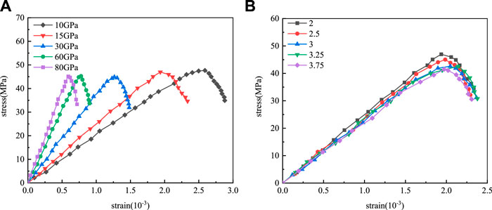
FIGURE 5. Deformation parameter calibration stress-strain curve. (A) Pb_emod calibration stress-strain curve; (B) Pb_kratio calibration stress-strain curve.
Parallel bond cohesion (Pb_coh), parallel bond tensile strength (Pb_ten) and parallel bond internal friction angle (Pb_fa) are the three strength parameters of particles. The stress-strain curves obtained from the uniaxial compression simulation is shown in Figure 6.
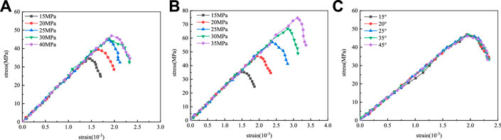
FIGURE 6. Strength parameter calibration stress-strain curve. (A) Pb_coh calibration stress-strain curve; (B) Pb_ten calibration stress-strain curve; (C) Pb_fa calibration stress-strain curve.
When the pb_coh increases from 15 MPa to 40 MPa, the peak strength increases from 35 MPa to approximately 46 MPa. The peak strength increases linearly with the increase of the cohesion and the Young’s modulus remains unchanged. When the pb_ten increases from 15 MPa to 35 MPa, the peak strength increases from 35 MPa to 72 MPa and the peak strength increases linearly with the tensile strength. The internal friction angle has little effect on the macroscopic elastic modulus and peak strength.
Uniaxial compression test by numerical simulation of specimens and after a somewhat tedious trial and error calibration process, the simulation results for the macro-mechanical behavior of the rock mass were obtained and the results are show in Figure 7.
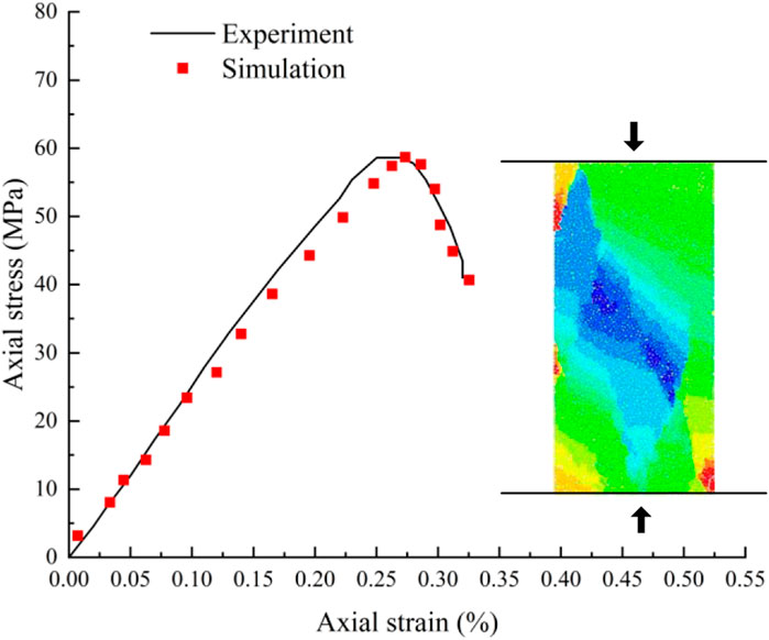
FIGURE 7. Typical mechanical responses and failure patterns of rocks under uniaxial compression tests.
We can see that the stress-strain curves correspond well to experimental observation of the filed rock. Therefore, the results obtained from the numerical tests can basically represent the macroscopic mechanical parameters of the surrounding rock. The determined micro-mechanical parameters are shown in Table 2.
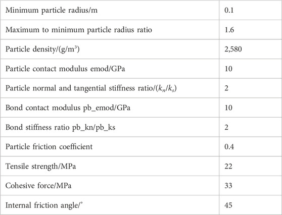
TABLE 2. Meso-parameters of class II surrounding rock.
In this section, the numerical model is assessed through the comparison with the analytical solutions of redistributed stress after excavation in circle tunnel. For this purpose, numerical simulations of underground cavern excavation were performed. The horizontal field stress of 15.5 MPa and the vertical field stress of 8.2 MPa were selected. According to the elastic mechanics, the tangential and radial stresses along the x-axis path of the tunnel center after excavation can be written as (Jaeger et al., 2009):
where,
The comparison between the analytical solution and the numerical simulation are shown in Figure 8. The magnitude of the tangential initial stress is equal to the vertical field stress, and the magnitude of the radial initial stress is equal to the horizontal field stress. It is obvious that the redistributed tangential stresses basically coincided with the analytical solution after the numerical simulation of excavation, and the radial stresses had some fluctuations but could also match well. Overall, the model met the expectation and is able to simulate the tunnel excavation well, providing a good simulation environment for the tunnel water-filling tests.
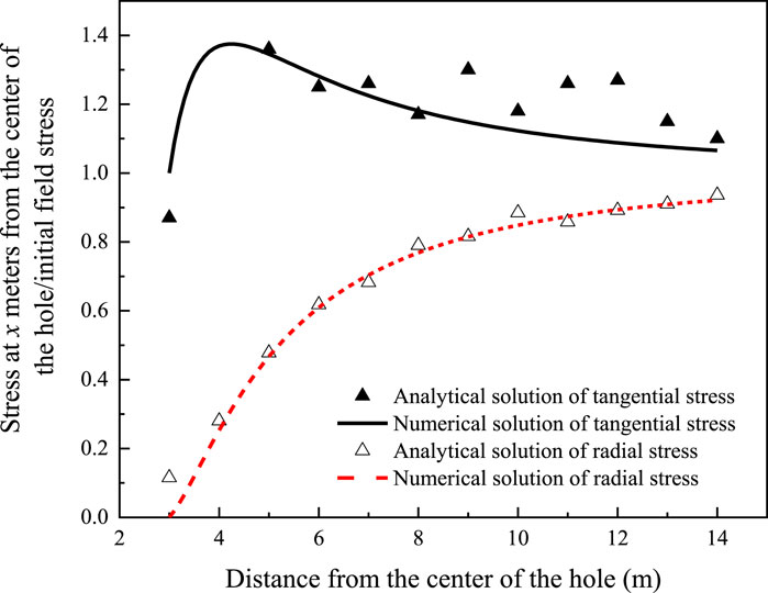
FIGURE 8. Comparison of numerical and analytical solutions of stresses after tunnel excavation.
Based on the simulation results of tunnel filling, the hydraulic fracturing process and failure mechanism of surrounding rock subjected to high internal pressure water can be revealed. In order to understand the hydraulic fracturing process more clearly,
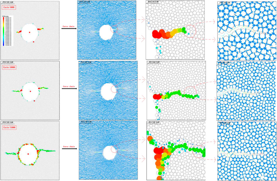
FIGURE 9. Development process of crack length under the action of high internal water pressure.
It can be seen from Figure 9 that under the action of high internal water pressure, the force on the surrounding rock at the cave wall is the largest, and fracturing occurs first. Once the pore water pressure exceeds the tensile strength of the rock mass, the connection between the rock mass particles is destroyed, and the pressure further causes the crack expansion. At the initial moment of fracturing, mainly horizontal cracks are produced, while the rock mass at other positions of the cave wall is relatively intact. As the crack expands, the water pressure in the expanded crack gradually decays with the increase of the crack length. When the crack extends to a certain distance, the crack propagation tends to be stable because the water pressure at the crack tip is less than the critical water pressure for fracturing of the surrounding rock. At the same time, small cracks are evenly distributed around the wall of the cave. Moreover, the connection between the particles near the induced cracks breaks and it mainly propagates along the HF cracks.
Figure 10 shows the water pressure applied on rock particles. After the hydraulic fracturing of the surrounding rock, the water pressure inside the crack gradually decreases with the increase of the fracturing length, and the pressure applied on the surrounding rock gradually decreases. At the tips of the cracks, the water pressure is not reduced to zero and it is smaller than the critical water pressure value of the surrounding rock. Therefore, the crack expansion tends to be stable.
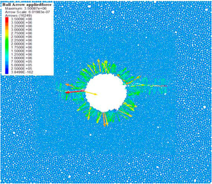
FIGURE 10. The water pressure applied on rock particles.
Internal water pressure is an important factor affecting hydraulic fracturing. Therefore, different water pressures are selected for fracturing simulation. Figure 11 shows the relationship curve between cycle steps and splitting crack length, as the number of cycle steps increases, the crack growth rate exhibits a slow-rapid-slow law. Figure 12 shows the relationship between internal water pressure and the maximum fracturing crack length. By simulating tunnel water filling under different high internal water pressures (0–15 MPa), it can be found that there is a critical threshold pressure
where,
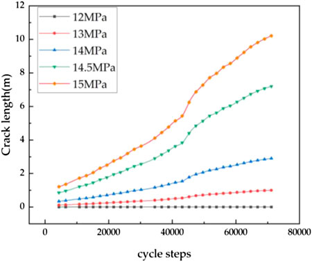
FIGURE 11. Relationship curve between cycle steps and splitting crack length.

FIGURE 12. Relationship curve between internal water pressure and splitting crack length.
As the crack grows, although the water pressure acting on the crack gradually decreases, the larger moment arm also leads to a larger splitting force, which also shows a secondary promotion effect on crack propagation. This secondary promotion makes the increase rate of the fracture length increase with the internal water pressure, and the fitting Eq. 6 also reflects the promotion effect of the internal water pressure on the fracture splitting length.
As shown in previous study, the development of crack length is significantly related to the mechanical properties of rock mass. The cohesion of rock mass is an important strength index of rock mass. To reveal the influence of rock cohesion on the hydraulic fracturing, five different cohesion value are designed and calculated using an internal water pressure of 14 MPa. The obtained numerical simulation results are shown in Figure 13. In Figure 13, the critical water pressure is defined as the pressure when the rock mass starts to fracture under the action of high internal water pressure.
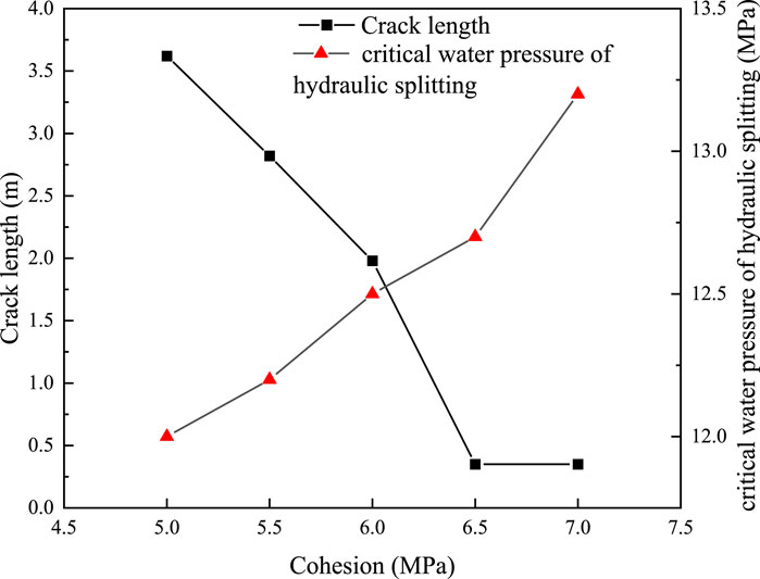
FIGURE 13. Influence of cohesion on fracturing results.
Numerical test results show that when the cohesion of rock mass changes from 5 MPa to 6 MPa, the length of the splitting fracture decreases almost linearly. When the cohesion reaches 6.5 MPa, the splitting length decreases sharply, and the crack development is basically inhibited. However, when the cohesive changes from 5 MPa to 7 MPa, the critical water pressure increases monotonously with the increase of cohesive. The cohesive affects the HF results significantly, and high cohesive force results in the inhibiting of the development of splitting cracks. This is because the increase in the cohesion of the rock mass will increase the bonding ability between the rock mass particles, and the connection between the rock mass particles will be less likely to be damaged, which increases the tensile strength of the rock mass in the direction of vertical crack development, thus inhibiting the HF. When the cohesion increases to a certain value, the HF effect of the internal water pressure is less than the anti-splitting ability of the rock mass, and HF does not occur again.
The internal friction angle of the rock is an important strength index. To study the effect of the internal friction angle on HF, only the internal friction angle parameter of the surrounding rock is changed in the numerical tests. The hydraulic fracturing at the internal water pressure of 14.0 MPa and 14.5 MPa is studied respectively. The obtained experimental results are shown in Figure 14.
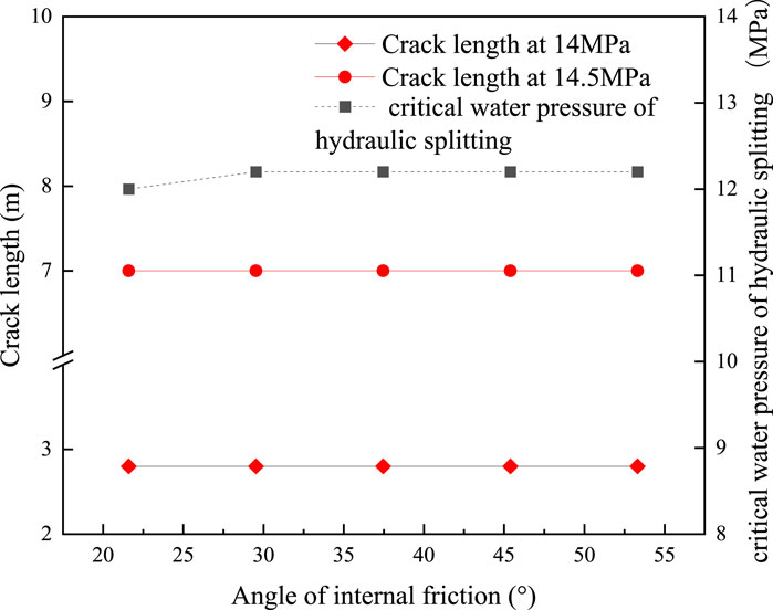
FIGURE 14. Influence of Internal Friction Angle on fracturing Results.
The simulation of HF under different internal friction angles reveals that the variation of internal friction angle has no effect on the crack development under both internal hydraulic pressures at a given field stress state. According to the numerical simulation results, the cracks produced between the particles after fracturing are tensile cracks, so the splitting damage under this field stress state is tensile. The internal friction angle reflects the magnitude of the internal frictional resistance of the rock mass. During the HF process, the distance between the particles becomes larger and the contract is destroyed, the frictional resistance is not reflected in this process. It does not play a role for the splitting damage in the tensile form, so the internal friction angle has little effect on the results of the crack length. At the same time, when the friction angle increases from 25° to 30°, the critical water pressure increases slightly. But when the internal friction angle changes from 30° to 50°, the critical water pressure stays constant.
Wang et al., 2014 found that the axial pressure of rock mass along the coal seam can amplify the fracturing damage capacity of high-pressure water flow. The greater the axial pressure along the coal seam, the easier it is to break. The smaller the axial pressure perpendicular to the coal seam, the easier it is to produce cracks. Through the directional injection hydraulic fracturing test, the fractured joint will deflect to the major horizontal principal stress direction after the fracture initiation. However, previous studies on the effect of principal stress on fracture initiation are rare, and the connection between the state of principal stress and fracture initiation under high internal water pressure is still worth studying.
In previous numerical tests, when the tunnel is filled with water at 12.0 MPa–15.0 MPa waterhead, hydraulic fracturing occurs in the surrounding rock, and the HF of the surrounding rock is along the direction of the major principal stress of the field stress. To further verify that the hydraulic fracturing after tunnel filling is along the direction of the major principal stress of the field stress, three different lateral pressure coefficients are used to simulate the tunnel filling process. The effect of the change in the direction of the principal stress of the ground after filling on the direction of HF of the surrounding rock are analyzed. The test simulation results are shown in Figure 15.
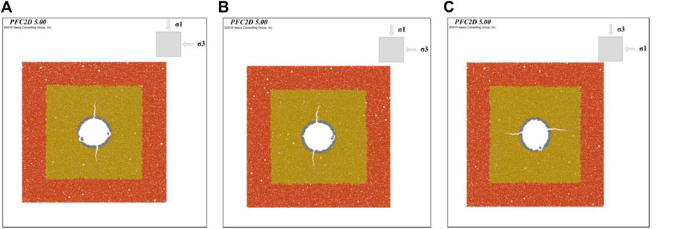
FIGURE 15. HF tests under different lateral pressure coefficients. (A) Lateral pressure coefficient 0.3; (B) Lateral pressure coefficient 0.5; (C) Lateral pressure coefficient 3.3.
The simulation results show that the major principal stresses in Figures 15A,B are in the vertical direction and the splitting direction is in the vertical direction. In Figure 15C, the major principal stress direction is in the horizontal direction and the splitting direction is also in the horizontal direction. It can be found that under different major principal stress directions, after the tunnel is filled with water, the surrounding rock is hydraulically split along different directions of horizontal and vertical. But the direction of fracturing is consistent with the direction of major principal stress. This reflects that after the tunnel is filled with water, the direction of the major principal stress will determine the direction of HF. This is because HF is rock tensile damage or tensile-shear damage, and the field principal stress will play a compressive role on the stratigraphic rock, making the particles denser, and the soil particles spacing smaller. Therefore, the compressed dense particles are more difficult to be separated, and the connection between the particles requires greater water pressure to pulled off. At this time, if the rock split not only to overcome its tensile properties but also to resist the field stress, which makes the rock mass in the direction of perpendicular to the major principal stress greater than the perpendicular to the minor principal resistance to splitting capacity. Therefore, the crack is more likely to unfold along the direction of the major principal stress.
To further investigate the effect of principal stress on hydraulic fracture, hydraulic fracture tests are conducted under different principal stresses. Five different types of major and minor principal stresses are used for water injection tests to obtain the law between the magnitude of the principal stress and the critical splitting pressure. The simulation results are also compared with the analytical solutions (Scholz, 1968):
where,
As shown in Figure 16, the critical fracture pressure is negatively correlated with the major principal stress. The critical fracture decreases with the increase of the major principal stress and the major principal stress plays a role in promoting fracture. The critical splitting pressure is positively correlated with the minor principal stress, and as the stress increases, the cracking pressure increases. The minor principal stress plays an inhibitory role in splitting. This also verifies the previous conclusion that the splitting process has to overcome the tension and field stress between the particles, so the larger the minor principal stress is, the larger the water pressure is needed, and the higher the cracking pressure is.
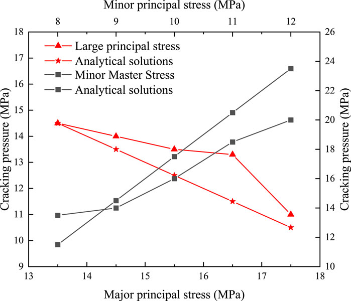
FIGURE 16. Cracking pressure versus principal stress curve.
It is very important to carry out the hydraulic fracturing analysis of different tunnel diameters for the tunnel lining structure design of the pumped storage power station. According to the established numerical model of the high internal water pressure tunnel, a waterhead of 14.0 MPa is applied in the tunnel to carry out the water filling simulation. The hydraulic fracturing of the surrounding rock after the high-pressure tunnel is filled with water under different apertures is analyzed. Figure 17 shows the fracture length of surrounding rock under high internal water pressure with different pore diameters. It can be seen that after the high-pressure tunnel is filled with water, the larger the diameter of the high-pressure tunnel, the longer the hydraulic splitting distance of the surrounding rock under the action of high internal water pressure. This may be due to the fact that the larger the tunnel diameter, the smaller the internal water pressure attenuation caused by the same split crack length, so the tunnel with a larger diameter needs longer split cracks to achieve stress balance. When the tunnel diameter is 4 m, the crack extends about 4.6 m. When the tunnel diameter is 8 m, the crack length increases to 6.5 m. The crack length of the surrounding rock is approximately linear with the tunnel diameter.
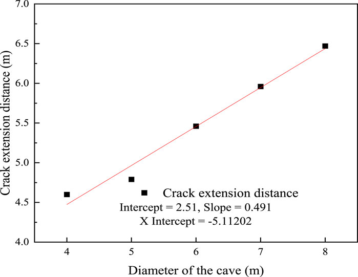
FIGURE 17. Relationship between tunnel diameter and fracturing crack length.
Discrete element method (DEM) is used to establish a hydraulic fracturing model and the water-rock coupling is considered in this paper. The mechanism of hydraulic fracturing in the tunnel surrounding rock under high internal water pressure is studied. The influence of major principal stresses in the formation on the direction of fracture development under high internal water pressure is initially explored, and the influence of formation parameters on the development of hydraulic fracturing is investigated. The mainly conclusions are as follows.
(1) Under the action of internal water pressure, the cavity wall of the surrounding rock first splits with two parallel cracks. Then water enters the cracks and causes the cracks to expand by squeezing the crack sidewall, and the expansion of the cracks by water pressure gradually decays until it is less than the critical fracturing pressure of surrounding rock. The relationship between internal hydraulic pressure and fracture splitting length can be describe an exponential function.
(2) The hydraulic fracturing is a tensile damage failure model. Cohesion inhibits the development of hydraulic fractures, and an increase in cohesion increases the fracture initiation pressure. The variation of the internal friction angle has little effect on the fractured radius and fracture initiation pressure. The increase in the cohesion of the rock mass will increase the bonding ability between the rock mass particles, and the connection between the rock mass particles will be less likely to be damaged, which increases the tensile strength of the rock mass in the direction of vertical crack development, thus inhibiting the HF.
(3) The direction of hydraulic fracturing under high internal water pressure is related to the ratio of major principal stress to minor principal stress. The surrounding rock splits preferentially along the direction of the major principal stress. The splitting process has to overcome the field stress and the tensile capacity between rock particles. The minor principal stress of the stratum is positively correlated with the critical fracturing pressure, and the major principal stress of the stratum is negatively correlated with the critical fracturing pressure. This conclusion is important for the control of hydraulic fracturing hazards. HF is rock tensile damage or tensile-shear damage, and the field principal stress will play a compressive role on the stratigraphic rock, making the particles denser, and the soil particles spacing smaller. Therefore, the compressed dense particles are more difficult to be separated, and the connection between the particles requires greater water pressure to pulled off. At this time, if the rock split not only to overcome its tensile properties but also to resist the field stress, which makes the rock mass in the direction of perpendicular to the major principal stress greater than the perpendicular to the minor principal resistance to splitting capacity. Therefore, the crack is more likely to unfold along the direction of the major principal stress. The fracturing crack length almost increases linearly with the increase of tunnel diameter. This may be due to the fact that the larger the tunnel diameter, the smaller the internal water pressure attenuation caused by the same split crack length, so the tunnel with a larger diameter needs longer split cracks to achieve stress balance.
The raw data supporting the conclusion of this article will be made available by the authors, without undue reservation.
Conceptualization, TJ and ZW; methodology, SS; software, PY; validation, QZ and PY; formal analysis, PY; investigation, QZ and QL; resources, TJ and ZW; data curation, QL and PY; writing–review and editing, PY; project administration, QZ; funding acquisition, QZ.
This work presented in this paper was financially supported by Jiangxi Province High Level and Skilled Leading Talent Training Project, Nanchang Rail Transit Group Co., Ltd. Technology Project and the Science and Technology Plan Project of China Construction Third Engineering Bureau.
Author TJ was employed by Nanchang Railway Transit Group Co., Ltd. Authors ZW and SS were employed by Metro Project Management Branch of Nanchang Rail Transit Group Co., Ltd. Authors QZ and QL were employed by China Con-struction Third Engineering Bureau Group Co., Ltd. The remaining author declares that the research was conducted in the absence of any commercial or financial relationships that could be construed as a potential conflict of interest.
The authors declare that this study received funding from Nanchang Rail Transit Group Co., Ltd. Technology Project and the Science. The funder had the following involvement in the study: conceptualization, methodology, investigation, resources. This study received funding from Technology Plan Project of China Construction Third Engineering Bureau. The funder had the following involvement in the study: validation, investigation, data curation, resources, project administration, funding acquisition.
All claims expressed in this article are solely those of the authors and do not necessarily represent those of their affiliated organizations, or those of the publisher, the editors and the reviewers. Any product that may be evaluated in this article, or claim that may be made by its manufacturer, is not guaranteed or endorsed by the publisher.
Al-Busaidi, A., Hazzard, J. F., and Young, R. P. (2005). Distinct element modeling of hydraulically fractured Lac du Bonnet granite. J. Geophys. Res-Sol. Ea. 110, B06302. doi:10.1029/2004JB003297
Britt, L. (2012). Fracture stimulation fundamentals. J. Nat. Gas. Sci. Eng. 8, 34–51. doi:10.1016/j.jngse.2012.06.006
Chukwudozie, C., Bourdin, B., and Yoshioka, K. (2019). A variational phase-field model for hydraulic fracturing in porous media. Comput. Method. Appl. M. 347, 957–982. doi:10.1016/j.cma.2018.12.037
Damjanac, B., Detournay, C., and Cundall, P. A. (2016). Application of particle and lattice codes to simulation of hydraulic fracturing. Comput. Part. Mech. 3 (2), 249–261. doi:10.1007/s40571-015-0085-0
Damjanac, B., and Cundall, P. (2016). Application of distinct element methods to simulation of hydraulic fracturing in naturally fractured reservoirs. Comput. Geotech. 71, 283–294. doi:10.1016/j.compgeo.2015.06.007
Ghassemi, A., Tarasovs, S., and Cheng, A. H. D. (2007). A 3-D study of the effects of thermomechanical loads on fracture slip in enhanced geothermal reservoirs. Int. J. Rock Mech. Min. 44 (8), 1132–1148. doi:10.1016/j.ijrmms.2007.07.016
Goodman, P. S., Galatioto, F., Thorpe, N., Namdeo, A. K., Davies, R. J., and Bird, R. N. (2016). Investigating the traffic-related environmental impacts of hydraulic-fracturing (fracking) operations. Environ. Int. 89-90, 248–260. doi:10.1016/j.envint.2016.02.002
Guo, T., Zhang, S., Qu, Z., Zhou, T., Xiao, Y., and Gao, J. (2014). Experimental study of hydraulic fracturing for shale by stimulated reservoir volume. Fuel 128, 373–380. doi:10.1016/j.fuel.2014.03.029
Huang, L. C., Ma, J. J., Lei, M. F., Liu, L. H., Lin, Y. X., and Zhang, Z. Y. (2020). Soil-water inrush induced shield tunnel lining damage and its stabilization: A case study. Tunn. Undergr. Sp. Tech. 97, 103290. doi:10.1016/j.tust.2020.103290
Jaeger, J. C., Cook, N. G. W., and Zimmerman, R. (2009). Fundamentals of rock mechanics. Malden, USA: Blackwell Publishing.
Jia, C., Zhang, S., and Xu, W. (2021). Experimental investigation and numerical modeling of coupled elastoplastic damage and permeability of saturated hard rock. Rock Mech. Rock Eng. 54 (3), 1151–1169. doi:10.1007/s00603-020-02319-5
Lecampion, B., and Detournay, E. (2007). An implicit algorithm for the propagation of a hydraulic fracture with a fluid lag. Comput. Method. Appl. M. 196 (49), 4863–4880. doi:10.1016/j.cma.2007.06.011
Legarth, B., Huenges, E., and Zimmermann, G. (2005). Hydraulic fracturing in a sedimentary geothermal reservoir: Results and implications. Int. J. Rock Mech. Min. 42 (7), 1028–1041. doi:10.1016/j.ijrmms.2005.05.014
Lei, M. F., Lin, D. Y., Huang, Q. Y., Shi, C. H., and Huang, L. C. (2020). Research on the construction risk control technology of shield tunnel underneath anoperational railway in sand pebble formation: A case study. Eur. J. Environ. Civ. En. 24 (10), 1558–1572. doi:10.1080/19648189.2018.1475305
Lei, M. F., Zhao, C. Y., Jia, C. J., and Shi, C. H. (2023). Study on the geological adaptability of the arch cover method for shallow-buried large-span metro stations. Tunn. Undergr. Sp. Tech. 132, 104897. doi:10.1016/j.tust.2022.104897
Li, L. C., Tang, C. A., Li, G., Wang, S. Y., Liang, Z. Z., and Zhang, Y. B. (2012). Numerical simulation of 3D hydraulic fracturing based on an improved flow-stress-damage model and a parallel FEM technique. Rock Mech. Rock Eng. 45 (5), 801–818. doi:10.1007/s00603-012-0252-z
Li, Y., Long, M., Tang, J., Chen, M., and Fu, X. (2020). A hydraulic fracture height mathematical model considering the influence of plastic region at fracture tip. Pet. explor. Dev. 47 (1), 184–195. doi:10.1016/S1876-3804(20)60017-9
Lin, Y. X., Li, C. H., Ma, J. J., Lei, M. F., and Huang, L. C. (2022). Effects of void morphology on fracturing characteristics of porous rock through a finite-discrete element method. J. Nat. Gas. Sci. Eng. 104, 104684. doi:10.1016/j.jngse.2022.104684
Lin, Y. X., Ma, J. J., Lai, Z. Z., Huang, L. C., and Lei, M. F. (2023). A FDEM approach to study mechanical and fracturing responses of geo-materials with high inclusion contents using a novel reconstruction strategy. Eng. Fract. Mech. 282, 109171. doi:10.1016/j.engfracmech.2023.109171
Lister, J. R., and Kerr, R. C. (1991). Fluid-mechanical models of crack propagation and their application to magma transport in dykes. J.Geophys. Res. Sol. Ea. 96 (B6), 10049–10077. doi:10.1029/91jb00600
McClure, M. W., Babazadeh, M., Shiozawa, S., and Huang, J. (2016). Fully coupled hydromechanical simulation of hydraulic fracturing in 3D discrete-fracture networks. SPE J. 21 (4), 1302–1320. doi:10.2118/173354-pa
Murdoch, L. C., and Slack, W. W. (2002). Forms of hydraulic fractures in shallow fine-grained formations. J. Geo. Geoenviron. 128 (6), 479–487. doi:10.1061/(ASCE)1090-0241(2002)128:6(479)
Patel, S. M., Sondergeld, C. H., and Rai, C. S. (2017). Laboratory studies of hydraulic fracturing by cyclic injection. Int. J. Rock Mech. Min. 95, 8–15. doi:10.1016/j.ijrmms.2017.03.008
Ren, Q., Dong, Y., and Yu, T. (2009). Numerical modeling of concrete hydraulic fracturing with extended finite element method. Sci. China Ser. E Technol. Sci. 52 (3), 559–565. doi:10.1007/s11431-009-0058-8
Scholz, C. H. (1968). Experimental study of the fracturing process in brittle rock. J. Geophys. Res. 73 (4), 1447–1454. doi:10.1029/JB073i004p01447
Shimizu, H., Murata, S., and Ishida, T. (2011). The distinct element analysis for hydraulic fracturing in hard rock considering fluid viscosity and particle size distribution. Int. J. Rock Mech. Min. 48 (5), 712–727. doi:10.1016/j.ijrmms.2011.04.013
Tan, P., Jin, Y., Han, K., Hou, B., Chen, M., Guo, X., et al. (2017). Analysis of hydraulic fracture initiation and vertical propagation behavior in laminated shale formation. Fuel 206, 482–493. doi:10.1016/j.fuel.2017.05.033
Wang, S. Y., Sun, L., Au, A. S. K., Yang, T. H., and Tang, C. A. (2009). 2D-numerical analysis of hydraulic fracturing in heterogeneous geo-materials. Constr. Build. Mat. 23 (6), 2196–2206. doi:10.1016/j.conbuildmat.2008.12.004
Wang, T., Zhou, W., Chen, J., Xiao, X., Li, Y., and Zhao, X. (2014). Simulation of hydraulic fracturing using particle flow method and application in a coal mine. Int. J. Coal Geol. 121, 1–13. doi:10.1016/j.coal.2013.10.012
Yan, C., Zheng, H., Sun, G., and Ge, X. (2016). Combined finite-discrete element method for simulation of hydraulic fracturing. Rock Mech. Rock Eng. 49 (4), 1389–1410. doi:10.1007/s00603-015-0816-9
Yu, J., Jia, C., Xu, W., Zhang, Q., and Wu, C. (2021). Granular discrete element simulation of the evolution characteristics of the shear band in soil–rock mixture based on particle rotation analysis. Environ. Earth Sci. 80 (6), 213. doi:10.1007/s12665-021-09484-y
Zhang, F., Dontsov, E., and Mack, M. (2017). Fully coupled simulation of a hydraulic fracture interacting with natural fractures with a hybrid discrete-continuum method. Int. J. Numer. Anal. Mater. 41 (13), 1430–1452. doi:10.1002/nag.2682
Zhao, C. Y., Lei, M. F., Jia, C. J., Zheng, K. Y., Song, Y. T., and Shi, Y. B. (2022). Asymmetric large deformation of tunnel induced by groundwater in carbonaceous shale. B. Eng. Geol. Environ. 81, 260. doi:10.1007/s10064-022-02757-1
Zhao, C. Y., Lei, M. F., Shi, C. H., Cao, H. R., Yang, W. C., and Deng, E. (2021). Function mechanism and analytical method of a double layer pre-support system for tunnel underneath passing a large-scale underground pipe gallery in water-rich sandy strata: A case study. Tunn. Undergr. Sp. Tech. 115, 104041. doi:10.1016/j.tust.2021.104041
Zhou, D., Zheng, P., He, P., and Peng, J. (2016). Hydraulic fracture propagation direction during volume fracturing in unconventional reservoirs. J. Pet. Sci. Eng. 141, 82–89. doi:10.1016/j.petrol.2016.01.028
Zhou, L., and Hou, M. Z. (2013). A new numerical 3D-model for simulation of hydraulic fracturing in consideration of hydro-mechanical coupling effects. Int. J. Rock Mech. Min. 60, 370–380. doi:10.1016/j.ijrmms.2013.01.006
Zhu, B. B., Lei, M. F., Gong, C. J., Zhao, C. Y., Zhang, Y. L., Huang, J., et al. (2022). Tunnelling-induced landslides: Trigging mechanism, field observations and mitigation measures. Eng. Fail. Anal. 138, 106387. doi:10.1016/j.engfailanal.2022.106387
Zimmerman, R. W., and Bodvarsson, G. S. (1996). Hydraulic conductivity of rock fractures. Transp. Porous Med 23 (1), 1–30. doi:10.1007/BF00145263
Keywords: high internal hydraulic pressure, hydraulic fracturing, discrete element method, fluid-solid coupling, field stress
Citation: Jiang T, Wu Z, Shan S, Zhong Q, Lu Q and Yang P (2023) DEM-based study of hydraulic fracturing mechanism under high internal water pressure. Front. Environ. Sci. 11:1251664. doi: 10.3389/fenvs.2023.1251664
Received: 02 July 2023; Accepted: 15 September 2023;
Published: 29 September 2023.
Edited by:
Sansar Raj Meena, University of Padua, ItalyCopyright © 2023 Jiang, Wu, Shan, Zhong, Lu and Yang. This is an open-access article distributed under the terms of the Creative Commons Attribution License (CC BY). The use, distribution or reproduction in other forums is permitted, provided the original author(s) and the copyright owner(s) are credited and that the original publication in this journal is cited, in accordance with accepted academic practice. No use, distribution or reproduction is permitted which does not comply with these terms.
*Correspondence: Pengliang Yang, eXBlbmdsaWFuZ0AxMjYuY29t
Disclaimer: All claims expressed in this article are solely those of the authors and do not necessarily represent those of their affiliated organizations, or those of the publisher, the editors and the reviewers. Any product that may be evaluated in this article or claim that may be made by its manufacturer is not guaranteed or endorsed by the publisher.
Research integrity at Frontiers
Learn more about the work of our research integrity team to safeguard the quality of each article we publish.