 Yingjie Hao
- 1Deep Mining Laboratory of Shandong Gold Group Co., Ltd., Laizhou, China
- 2Shandong Key Laboratory of Deep-Sea and Deep-Earth Metallic Mineral Intelligent Mining, Laizhou, China
- 3School of Mines, China University of Mining and Technology, Xuzhou, China
Split-set bolt is widely used in supporting stope and roadway surrounding rock in metal mines. The maximum pull-out force generated by the relative slippage between the anchor bolt and the drill hole can serve as an indicator for assessing its anchoring force, and the anchoring force of the grouted anchor bolt exhibits certain regularity over time. This pull-out test was carried out at different time points after the construction of the split-set bolt by using the drawing equipment, and the variation law of its anchoring force with time was studied. The anchoring force on per unit area of surrounding rock is selected as a evaluation parameter, and the reinforcement support scheme of surrounding rock is optimized from the aspects of stress release of surrounding rock in the initial stage of excavation and stability of anchoring force on per unit area of surrounding rock. The convergence monitoring measurement method of roadway surrounding rock is adopted, and the same bolt drawing area is selected to verify the feasibility of the reinforcement support scheme. The effectiveness of the reinforcement scheme is verified by monitoring and comparing the roof subsidence and the lateral convergence of two walls between two different support schemes.
1 Introduction
Split-set bolt is composed of bolt body and plate, which belongs to a full-length anchoring friction bolt (SHI, 2014; WU et al., 2020; DONG et al., 2022; Liu and Li, 2023). Split-set bolt has many advantages, such as convenient installation, low price and suitable for all kinds of rocks, so it is widely used in the surrounding rock support of metal mine stope and roadway (CAI, 2020; HOU et al., 2021; Liu et al., 2023a). In the construction of split-set bolt, the bolt hole is firstly drilled in the surrounding rock of the roadway, and then the bolt body is fed into the hole by the impact of the driller (DU et al., 2021; Linpo, 2022; Liu et al., 2023b). The diameter of the bolt hole is generally slightly smaller than that of the bolt, so that the bolt is squeezed and deformed in the borehole to produce friction with the surrounding rock. The friction force connects the bolt and the surrounding rock into a whole and plays a reinforcing role in the surrounding rock. When the bolt is subjected to radial drawing force, the drawing force is equal to the friction resistance between the bolt and the hole wall (SU et al., 2020; WANG et al., 2022; XIE et al., 2022; Zhang et al., 2023a). The research shows that in the static equilibrium state, the anchoring force of the split-set bolt is equal to the maximum drawing force when the bolt fails (Ma et al., 2018; Ma et al., 2019; ZHANG et al., 2020). Therefore, the maximum drawing force when the bolt slips relative to the borehole can be used as the index to evaluate the anchoring force.
After the construction of the bolt, with the continuous deformation of the surrounding rock of the roadway, the fracture of the borehole and the aperture may change, resulting in variations of deformation and stress of the bolt body. Therefore, the anchoring force exhibits a certain regularity over time (ZHANG et al., 2020; XIE et al., 2021; LUAN et al., 2022; Zhang et al., 2023b; Li et al., 2023). In this paper, through the time-varying test of the drawing force of the split-set bolt after the excavation of the roadway, the time-varying law of the anchoring force is studied, in order to form a guidance for the selection of the reinforcement time for the surrounding rock of the roadway.
2 Overview and engineering technical conditions of the mine
Chifeng Chaihulanzi Gold Mining Co., Ltd. (hereinafter referred to as “Chaihulanzi Gold Mine”) is located in the east of Chaihulanzi Village, Chutoulang Town, Songshan District, Chifeng City, Inner Mongolia Autonomous Region. It is now a subsidiary company of Shandong Gold Mining Co., Ltd. The administrative division belongs to Chutoulang Town, Songshan District, Chifeng City.
A number of veins are distributed in the Chaihulanzi gold mining area, of which 5# vein is the main mining vein. The ore body strikes about 126°, dips to the southwest, and the dip angle is about 78°. The ore body is composed of gold-bearing quartz vein and gold-bearing diorite porphyrite. The rock fractures are developed, and the fractures are filled with disseminated and fine vein pyritization. The boundary between the orebody and the surrounding rock is clear, and the hanging wall of the orebody is a graphite schist fracture zone, which has a certain impact on mining. The footwall of the ore body is diorite porphyrite, and the rock joints on the hanging wall are very developed. The roadway outside the vein along the footwall of the ore body is being constructed, and the mining tunnels for vein exploration is constructed at every 50 m interval. At present, the exploration cross vein has been constructed to the 15th line on 14th level, and it has been constructed to the 22nd line on 17th level.
3 Field test of drawing force of split-set bolt
3.1 Bolt drawing test system
Bolt drawing test system is a set of intelligent test system which integrates bolt drawing, data acquisition and real-time data display and it is independently developed by Deep Mining Laboratory of Shandong Gold Group Co., Ltd. The bolt drawing test system is divided into two parts: loading box and acquisition box. The loading box is mainly composed of jack, tubing, reaction cylinder, connectors, nuts and sensors. The items in the loading box are related devices used in the bolt drawing. The acquisition box is composed of acquisition system, industrial and control integrated machine, acquisition module, battery pack and charging group. The acquisition box is equipped with a self-developed acquisition system, which is responsible for the real-time transmission of on-site drawing force and tensile displacement information. The accessories are shown in Figure 1, and the assemblage of the loading box is shown in Figure 2.
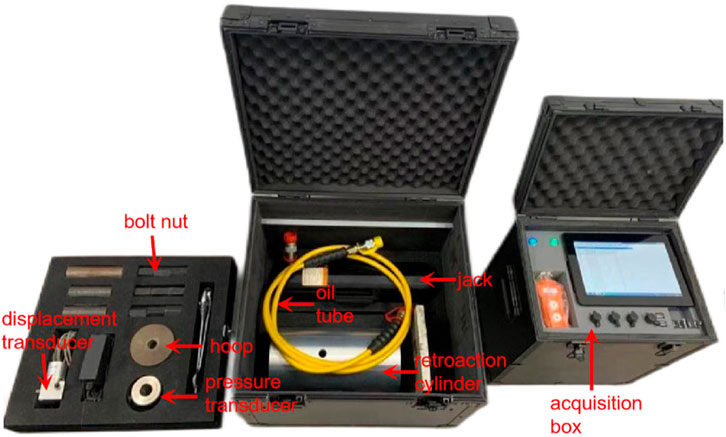
FIGURE 1. Composition of bolt drawing test system.
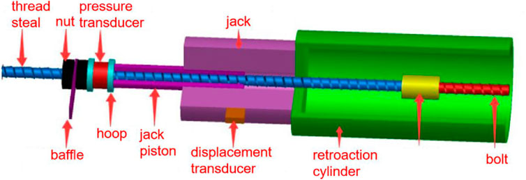
FIGURE 2. Schematic diagram of on-site test system installation of pull-out equipment.
3.2 Drawing test scheme
In order to obtain sufficient sample data and ensure the objectivity and accuracy of the test results, the 5# vein at the 15th line of the outer roadway of Level 14 and the 5# vein at the 23rd line of the outer roadway of Level 17 were selected as the locations for testing the variation of the anchoring force under pull-out force. Five groups of 15 bolts were constructed in each of the two sites, 3 in each group. All bolts on each level are constructed at the same time. Bolt on-site layout on 14th level and 17th level are shown in Figures 3, 4, and the bolt layout plans are shown in Figures 5, 6.
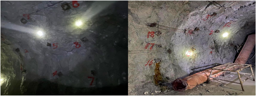
FIGURE 3. Bolt on-site layout on 14th level.
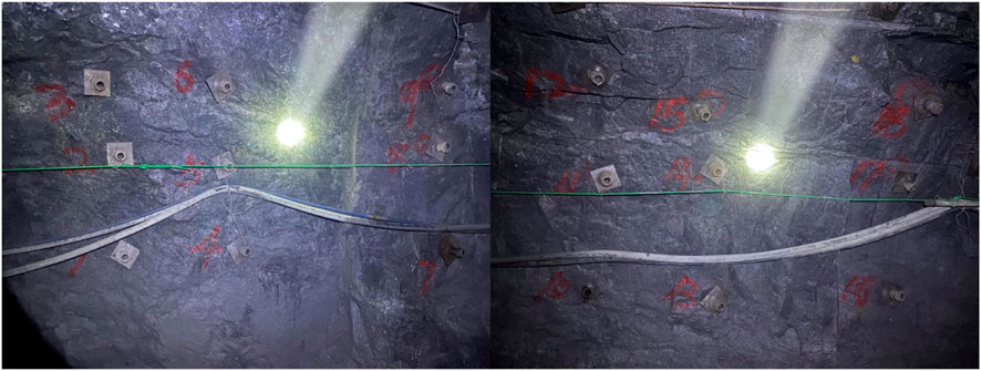
FIGURE 4. Bolt on-site layout on 17th level.
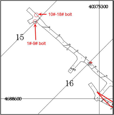
FIGURE 5. Blot layout plan on 14th level.
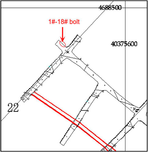
FIGURE 6. Blot layout plan on 17th level.
As shown in Table 1, the time interval from construction to drawing is 1 h, 24 h, 3 days, 7 days and 14 days respectively.
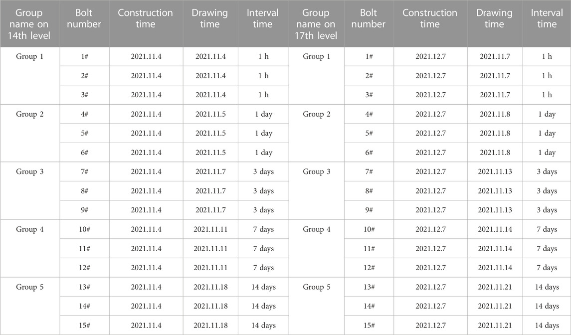
TABLE 1. Schedule of bolt drawing test.
3.3 Drawing test results and analysis of time-varying law in anchoring force
Using the bolt drawing test system, the pre-construction bolts are pulled out according to the design interval time. The scene of some of the pulled-out bolts is shown in Figure 7, and the time-drawing force curve of some bolts is shown in Figure 8. The obtained drawing test results are shown in Table 2.
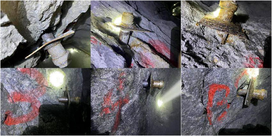
FIGURE 7. Fild after bolt drawing.
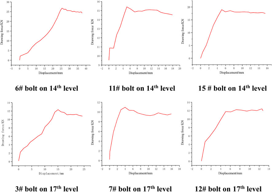
FIGURE 8. Displacement-drawing force curve of bolt.
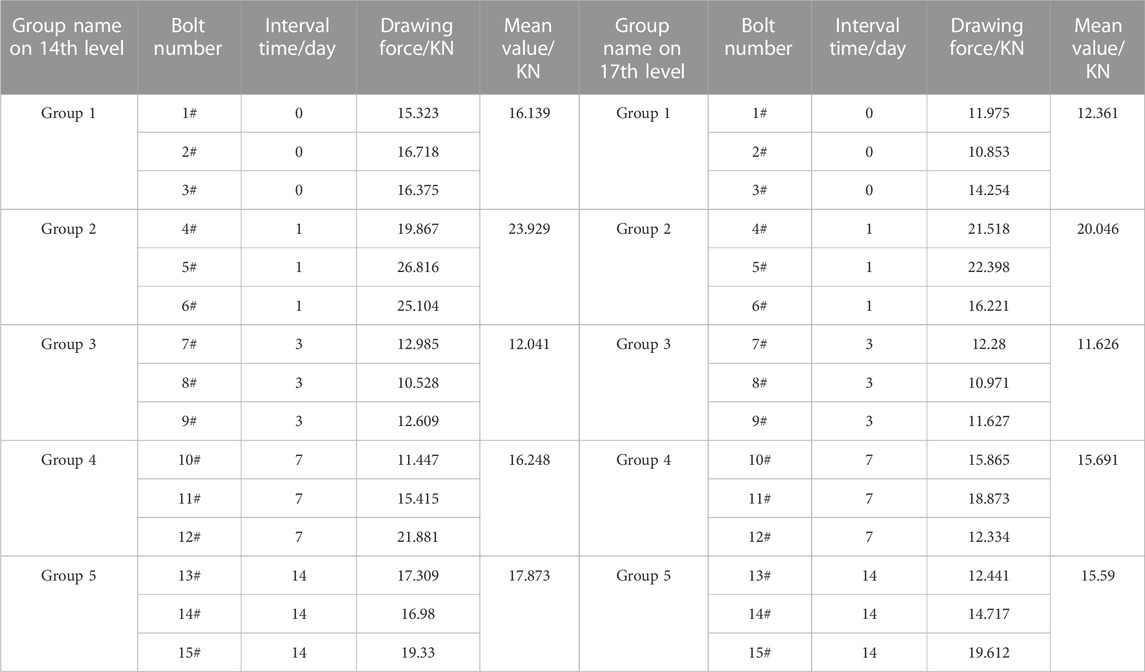
TABLE 2. Test data of drawing force.
To compare the time-varying curves of the drawing force of the split-set bolts comprehensively on the 14th level with that in 17th level (Figure 9). The curves show that the drawing force of the bolt on 14th level is higher than that on 17th level at each time point, but the trend of the drawing force curve of the bolt is the same. The drawing force is low at 1 h (0 day) in the initial stage of bolt construction, and then the drawing force increases to the peak at 1 day, with an increase of more than 40%. Subsequently, the curve decreased to the lowest value at 3 days, and the anchoring force decreased to about 50% of the peak value at 1 day. In the range of 3 days–14 days, the drawing force of the bolt gradually increased but the trend slowed down. The anchoring force changed little in the range of 7 days–14 days, which could be regarded as the anchoring force entering a stable period after 7 days of bolt construction.
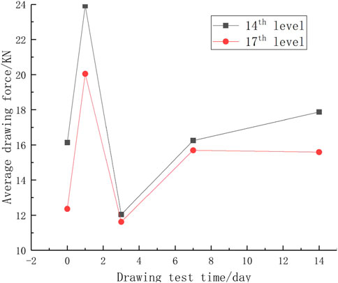
FIGURE 9. Time-varying curve of average drawing force.
4 The current support scheme and improvement
According to the analysis results of the time-varying curve of the bolt drawing force, it can be seen that the anchoring force of the split-set bolt decreased to the lowest value on the third day after construction, and the supporting effect on the surrounding rock also decreased to the lowest at the same time. At this moment, the elastic strain energy accumulated in the early stage is released sharply with the decrease of support strength, which is easy to cause the failure of surrounding rock such as the collapse of roadway roof. Therefore, it is considered to reinforce the surrounding rock within a certain period of time after the construction of the first batch of bolts to compensate for the decrease of the anchoring force, so that the anchoring force of the surrounding rock is always in a stable range, so as to ensure that the surrounding rock stress can be effectively dealt with after excavation. It is planned to construct the second batch of reinforcing bolts at 1 day, 2 days and 3 days after the construction of the first batch of bolts, which are named scheme 1, 2 and 3 respectively.
In the original scheme, the spacing between bolts is 0.64 m, and the diamond mesh is fixed on the surface of surrounding rock to strengthen the supporting effect. In the construction of the reinforcement support scheme, the first batch of bolts is first constructed, and the diamond mesh is fixed on the surface of the surrounding rock. The spacing between the bolts is 0.9 m. After the first batch of bolts are constructed for a certain period, the reinforcing bolts are intensive installed at the intersection of the rectangular diagonals of the first batch of bolts. The reinforcing support scheme is shown in Figure 10. Based on the time-varying curve data of drawing force on 14th level, the time-varying curve of anchoring on per unit area of three schemes is drawn, and the best reinforcement support scheme is selected according to the curve. Because the drawing force data of the bolt were not obtained after 14 days, but the curve showed that the drawing force basically stabilized after 7 days. Therefore, it is assumed that the anchor force of the bolt will not change after 14 days. The calculation results of the anchoring force on per unit area of the original scheme and the reinforcement support scheme at different times are shown in Table 3.
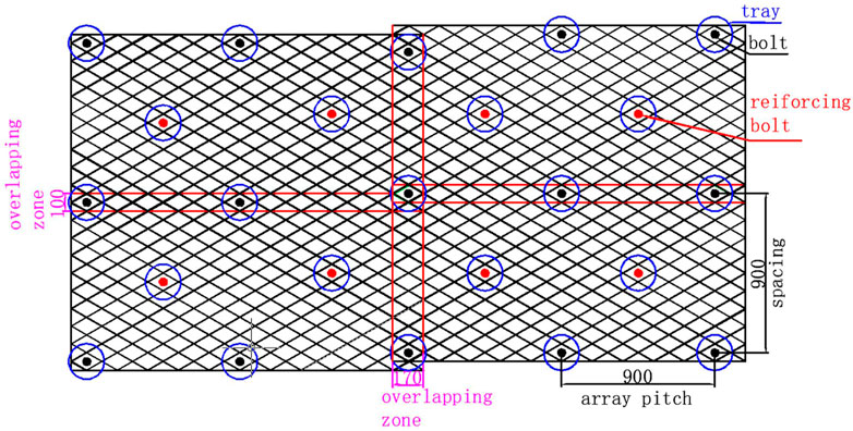
FIGURE 10. Reinforcement support scheme diagram.
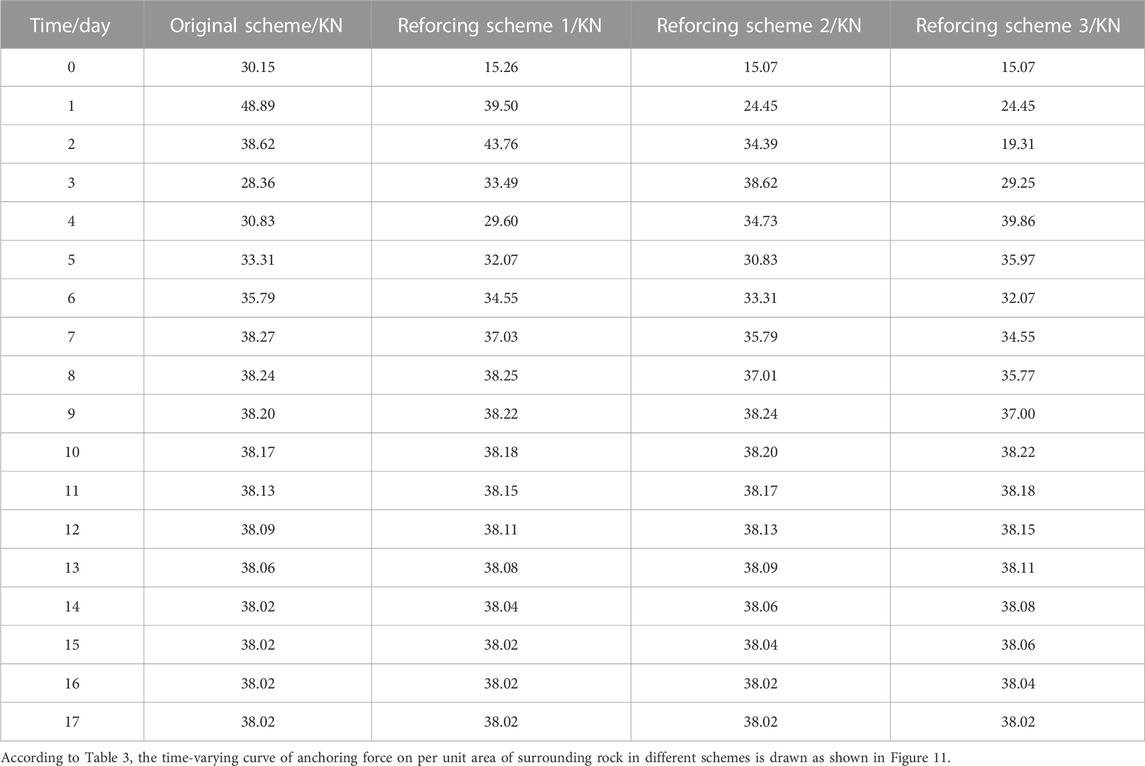
TABLE 3. Anchoring force on per unit area of surrounding rock in different schemes.
From Figure 11, it can be seen that under different reinforcement and support schemes, the time when the anchoring force of surrounding rock on per unit area reaches the maximum value is different. The earlier the reinforcing bolts are constructed, the faster the maximum anchoring force is obtained. In addition to the reinforcement scheme 3, the earlier the reinforcement support is constructed, the greater the maximum anchoring force value, but the greater the difference between the maximum and minimum values. In reinforcement scheme 3, the anchoring force on per unit area gradually stabilized after 10 days, and the difference between the schemes was not large, which was stable at about 38 kN/m2. The anchoring force of the original scheme, the reinforcement scheme 1 and the reinforcement scheme 2 has the same change trend, which gradually reaches the highest value after the reinforcement support, and then decreases to a certain extent and finally tends to be stable. Different from other schemes, the reinforcement support construction of scheme 3 lags behind the initial support time for a long time, and the time to reach the maximum anchoring force is the latest. Therefore, the anchoring force curve finally tends to be stable after two maximum values and two minimum values appear. Comparing the three reinforcement support schemes with the original scheme, the variation of anchoring force on per unit area is smaller than that of the original scheme, and the anchoring force is more stable.
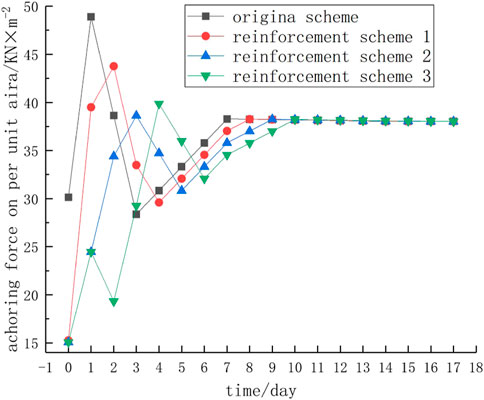
FIGURE 11. Time-varying curve of anchoring force on per unit area of surrounding rock in different schemes.
The research shows that the surrounding rock can release elastic strain energy rapidly in a short time after excavation, and the deformation of the surrounding rock is also the largest, after that the surrounding rock gradually enters a stable period. Therefore, considering the energy release of surrounding rock and the stability of anchoring force on per unit area of surrounding rock, scheme 2 is selected as the final reinforcement support scheme, that is, the reinforcement bolt construction is carried out after 2 days of the first batch of bolt construction. According to the principle of supporting and relieving pressure, at this point, it is possible to avoid the period of intense release of energy from the surrounding rock. As soon as a small deformation appears in the surrounding rock, reinforcement and support should be carried out immediately to compensate for the decrease in anchoring force of the anchor bolt caused by single-time construction. This would maintain a relatively stable anchoring force per unit area, thereby achieving the objective of rational support for the surrounding rock.
5 Field application
The convergence of roadway surrounding rock is the most basic data to confirm the stability of surrounding rock and judge the supporting effect. In this paper, the convergence monitoring of roadway surrounding rock is adopted to compare the support effect of the two schemes and demonstrate the feasibility of the new scheme.
5.1 Monitoring principle and equipment
The JSS30A digital display convergence meter uses the method of mechanical transmission displacement to convert the relative displacement between the two reference points into the numerical difference of the digital display displacement meter. When the hook is used to link the two reference points A and B that embedded in the surrounding rock, the constant tension for the steel ruler can be generated by changing the length of the convergence meter body, so as to ensure the accuracy and comparability of the measurement. The change of the length is measured by the digital display circuit. When the relative displacement between points A and B occurs with time, the readings measured at different times are obtained, and the difference is the relative displacement between points A and B. When the relative displacement between two points exceeds the effective range of the digital displacement meter, the difference can still be read by the digital displacement meter by adjusting the pin inserted into the scale hole.
The monitoring uses a simple and verifiable triangular wiring method for installation testing, as shown in Figure 12. The relative deformation of the two sides of the roadway can be obtained by the change of the line BC. Through the change of AB and AC, the displacement of roof can be acquainted.
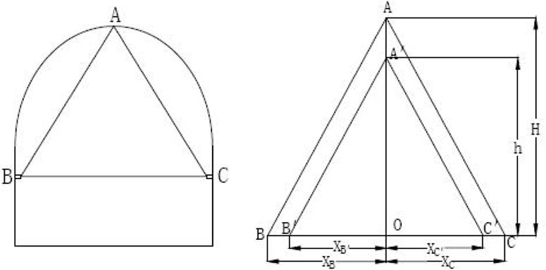
FIGURE 12. Principle and layout diagram of surrounding rock convergence deformation measurement.
The displacement convergence S between two measuring points is calculated according to the following formula:
Where: Lo——first reading of steel ruler, mm;
Ln——the nth reading of steel ruler, mm;
Do——first reading of digital display, mm;
Dn——the nth reading of digital display, mm。
In order to obtain the displacement of each measuring point, the closed triangle method can be used to analyze the solution. In order to facilitate the analysis and calculation to do the following three assumptions:
(1) The deformation of surrounding rock occurs in the section perpendicular to the axis of roadway.
(2) The vertex A is at the center line of the roadway, and there is only vertical displacement, that is:
(3) Measuring point B, C at two sides of the roadway is at the same level, the vertical displacement of two points is neglected, that is:
It can be seen from Figure 12 that AO
Similarly, the distance h, XB′, XC′ from point O to each point can be obtained. The displacement of each measuring point is:
The main contents of the monitoring are the convergence of the two sides and the roof subsidence. The JSS30A digital convergence meter is adopted, and the measuring points are completed with self-made anchor bolts. The appearance of the digital convergence meter is shown in Figure 13, and the internal structure diagram is shown in Figure 14.
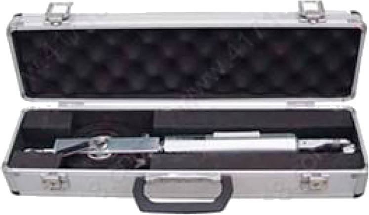
FIGURE 13. Appearance of convergence meter.
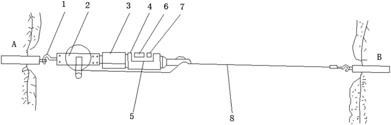
FIGURE 14. Internal structure diagram of digital convergence meter. 1 hook; 2-ruler supporter; 3-regulating nut; 4-shell; 5-plastic cover; 6-show window; 7-tension window; 8-steel ruler.
5.2 Monitoring results and data analysis
The reinforcement support scheme and the original support scheme are respectively constructed at the 21-line roadway along with 5# vein on 17th level, and the convergence data of surrounding rock after construction of the two support schemes are obtained.
The monitoring data of surrounding rock convergence after the construction of the original support scheme are shown in Table 4, and the convergence curve is shown in Figures 15, 16.
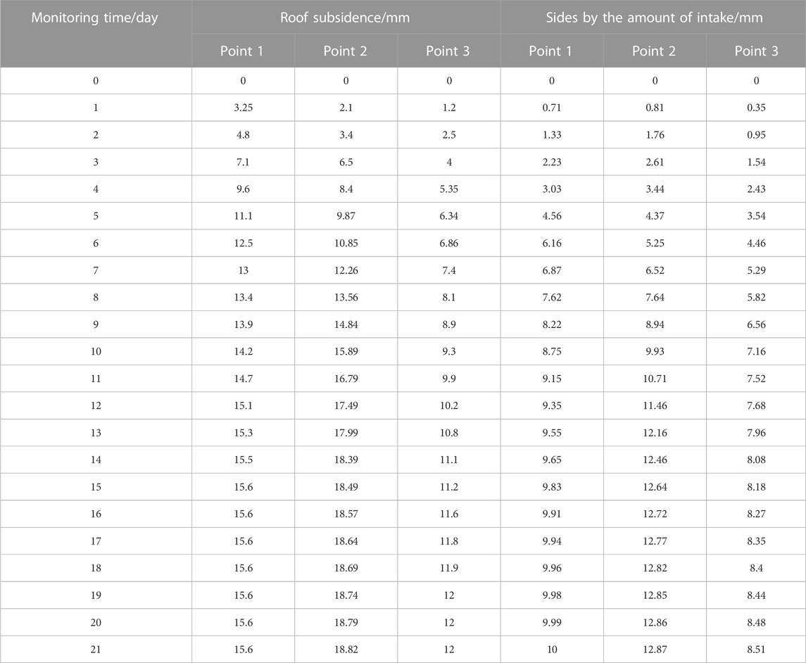
TABLE 4. Monitoring data of 1 #, 2 # and 3 # measuring points on 14th level.
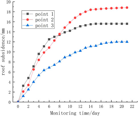
FIGURE 15. Roof subsidence of support scheme.
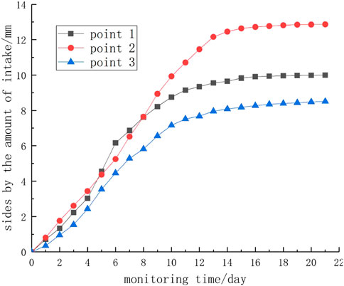
FIGURE 16. Lateral displacement occurred in original support scheme two wall with the original support scheme.
The convergence monitoring data of the improved support scheme are shown in Table 5, and the convergence curve is shown in Figures 17, 18.
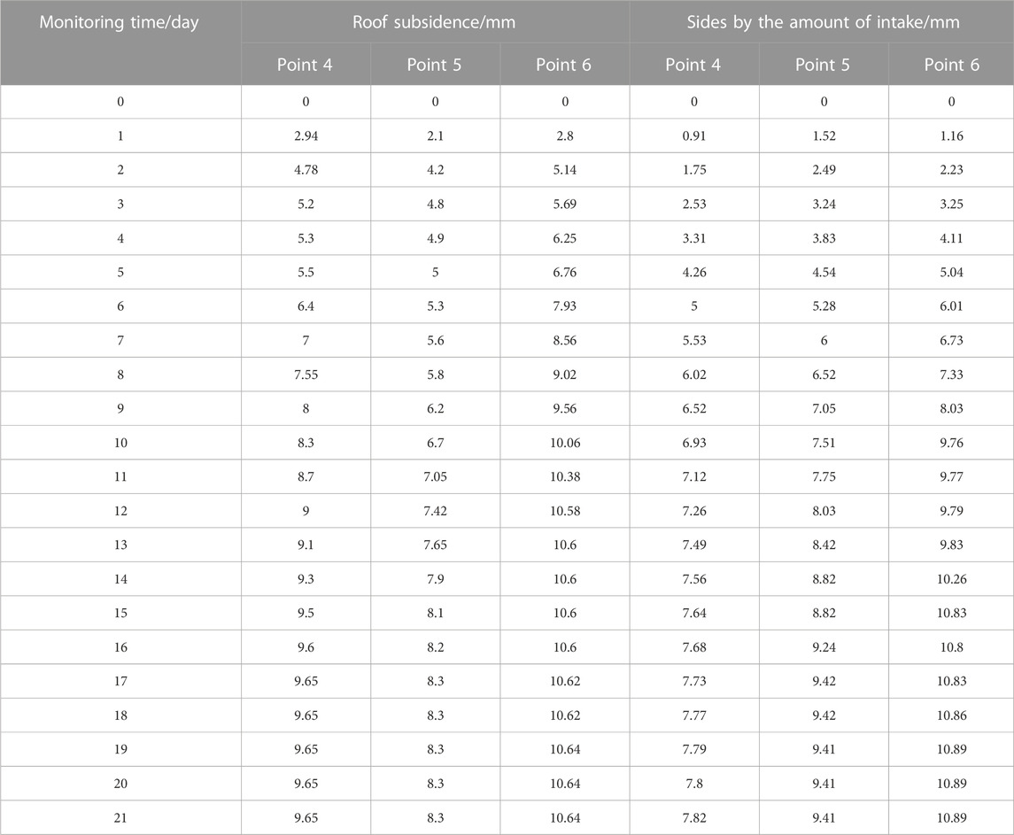
TABLE 5. Monitoring data of 4 #, 5 # and 6 # measuring points on 14th level.
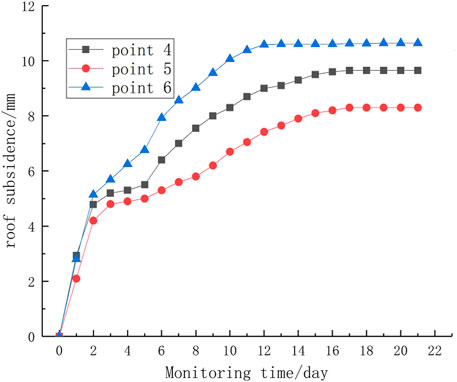
FIGURE 17. Roof subsidence of improved support scheme.
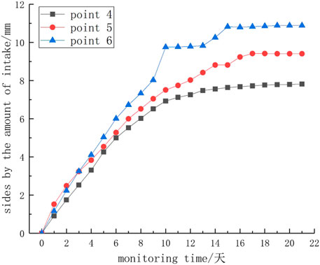
FIGURE 18. Lateral displacement decreasing in two improved support scheme walls after improving support scheme.
From the comparative analysis of the monitoring data after the application of the two schemes, it can be seen that after the application of the improved support scheme, the final roof subsidence and the displacement of measuring points in two sides are reduced to a certain extent compared with the original scheme. Comparing the monitoring data of the original scheme (Figure 15, 16) and the improved scheme (Figures 17, 18), it can be seen that the roof subsidence and the displacement of the two sides of the improved scheme increased rapidly in the first 2 days, and the values were greater than the original scheme. The growth rate of roof subsidence and two-side movement in the range of 2 days–5 days is lower than that of the original scheme, and the monitoring value of the original scheme is greater than that of the improved scheme in 5 days. The monitoring data is consistent with the time-varying curve of the anchoring force of the support scheme, which proves the effectiveness of the scheme.
6 Conclusion
(1) Through the drawing force test of the split-set bolt at different time intervals after construction, the time-varying law of the drawing force of the split-set bolt is compared and summarized. That is to say, the drawing force is low in the first hour of bolt construction, and the drawing force increases to the peak on the first day, and then it decreases to the lowest value on the third day. In the range of 3 days–14 days, the drawing force of the bolt gradually increased but the trend slowed down. Among them, the anchoring force changed little from 7 days to 14 days, that is, the anchoring force has entered a stable period after 7 days of bolt construction.
(2) According to the time-varying law of the anchoring force of the split-set bolt, the anchoring force on per unit area of the surrounding rock is selected as the evaluation parameter. Considering the energy release of the surrounding rock at the initial stage of excavation and the stability of the anchoring force on per unit area of the surrounding rock, Scheme 2 is selected as the final reinforcement support scheme, that is, the reinforcement bolt construction is carried out 2 days after the first batch of bolt construction.
(3) The feasibility of the reinforcement support scheme was verified at the 21st line roadway along with the 5# vein on 17th level. The convergence deformation measurement method of the surrounding rock of the roadway was used to monitor and compare the roof subsidence and the two-side movement data of the two support methods. The monitoring results show that the convergence curve of surrounding rock before and after the application of the improved support scheme has the same trend as the time-varying curve of bolt drawing force. After the application of the improved support scheme, the final convergence of surrounding rock is reduced to a certain extent compared with the original scheme, which verifies the effectiveness of the improved support scheme.
Data availability statement
The original contributions presented in the study are included in the article/Supplementary Material, further inquiries can be directed to the corresponding author.
Author contributions
YH develops and implements the drawing-force test plan, analyses the drawing-force data and writes the article. MZ and CW are responsible for surrounding rock convergence detection. KH and PH are responsible for typesetting the article. All authors contributed to the article and approved the submitted version.
Conflicts of interest
Authors YH, MZ, CW, YY, and KH were employed by Deep Mining Laboratory of Shandong Gold Group Co., Ltd.
The remaining author declares that the research was conducted in the absence of any commercial or financial relationships that could be construed as a potential conflict of interest.
Publisher’s note
All claims expressed in this article are solely those of the authors and do not necessarily represent those of their affiliated organizations, or those of the publisher, the editors and the reviewers. Any product that may be evaluated in this article, or claim that may be made by its manufacturer, is not guaranteed or endorsed by the publisher.
References
Cai, Meifeng (2020). Key theories and technonogies for surrounding rock stability and ground control in deep mining. J. Min. Strata Control Eng. 2 (3), 033037. doi:10.13532/j.jmsce.cn10-1638/td.20200506.001
Dong, X., Ma, Z., Zheng, L. I., et al. (2022). Study on coupling model of anchorage force loss and time-dependent deformation of rock-soil mass. Chin. J. Rock Mech. Eng. 41 (6), 1093–1102. doi:10.13722/j.cnki.jrme.2021.0759
Du, Y., Guorui, F. E. N. G., Kang, H., et al. (2021). Investigation on the pull-out bearing characteristics of bolts with different bond lengths. J. Min. Strata Control Eng. 3 (3), 033012. doi:10.13532/j.jmsce.cn10-1638/td.20210125.001
Hou, C., Wang, X., Bai, J., et al. (2021). Basic theory and technology study of stability control for surrounding rock in deep roadway. J. China Univ. Min. Technol. 50 (1), 1–12. doi:10.13247/j.cnki.jcumt.001242
Li, X. L., Zhang, X. Y., and Shen, W. L. (2023). Research on the mechanism and control technology of coal wall sloughing in the ultra-large mining height working face. Int. J. Environ. Res. Public Health 20 (2), 868. doi:10.3390/ijerph20010868
Linpo, S. I. (2022). Experimental study on mechanical properties of rock bolts under tension and shear loads. J. Min. Strata Control Eng. 4 (3), 033038.doi:10.1016/j.jrmge.2014.06.002
Liu, S. M., and Li, X. L. (2023). Experimental study on the efect of cold soaking with liquid nitrogen on the coal chemical and microstructural characteristics. Environ. Sci. Pollut. Res. 30 (3), 36080–36097. doi:10.1007/s11356-022-24821-9
Liu, S. M., Sun, H. T., and Zhang, D. M. (2023). Experimental study of effect of liquid nitrogen cold soaking on coal pore structure and fractal characteristics. Energy 275 (7), 127470. doi:10.1016/j.energy.2023.127470
Liu, S. M., Sun, H. T., and Zhang, D. M. (2023). Nuclear magnetic resonance study on the influence of liquid nitrogen cold soaking on the pore structure of different coals. Phys. Fluids 35 (1), 012009. doi:10.1063/5.0135290
Luan, H., Cao, Y., Jiang, Y., et al. (2022). Implementation of tension-shear coupling failure mode of bolts in FLAC3D and its application. J. Min. Strata Control Eng. 4 (6), 063029. doi:10.13532/j.jmsce.cn10-1638/td.20220727.002
Ma, J., Dong, L., Zhao, G., and Li, X. (2018). Discrimination of seismic sources in an underground mine using full waveform inversion. Int. J. Rock Mech. Min. Sci. 106, 213–222.doi:10.1016/j.ijrmms.2018.04.032
Ma, J., Dong, L., Zhao, G., and Li, X. (2019). Focal mechanism of mining-induced seismicity in fault zones: A case study of yongshaba mine in China. Rock Mech. Rock Eng. 52 (9), 3341–3352. doi:10.1007/s00603-019-01761-4
Shi, S. (2014). Reaearch on the anchorage mechanism of bolt under the loading of pullout. Lanzhou, China: University of Lanzhou.
Su, S., Du, Y., Zhu, J., Zhao, Z. L., Meng, B., et al. (2020). Numerical study on bearing behavior of layered rock mass for deep roadway. J. Min. Strata Control Eng. 2 (1), 013002.doi:10.1016/j.tust.2021.103968
Wang, Z., Jiang, P., and Meng, X., (2022). Numerical study of support effectiveness and mechanism of pre-stressed bolts. J. Min. Strata Control Eng. 4 (4), 043015. doi:10.13532/j.jmsce.cn10-1638/td.20220620.002
Wu, D., Li, Y., and Qian, Y., (2020). Study on surrounding rock control technology of roadway in deep fractured rock mass. Metal. Mine 8, 1–7. doi:10.19614/j.cnki.jsks.202008001
Xie, L., Zhang, D., and Liang, S. (2022). Optimisation and simulation of the effect of grouted cable bolts as advanced support in longwall entries. J. Min. Strata Control Eng. 4 (3), 033011. doi:10.13532/j.jmsce.cn10-1638/td.20220309.001
Xie, Z., Zhang, N., and An, C., (2021). Research on principle and application of roof thick layer cross-boundary anchorage in coal roadways. Chin. J. Rock Mech. Eng. 40 (6), 1195–1208. doi:10.13722/j.cnki.jrme.2020.0970
Zhang, C., Song, W., and Fu, J., (2020). Study on roadway management technology of broken rock mass in submarine gold mine. J. Min. Strata Control Eng. 2 (3), 033039. doi:10.13532/j.jmsce.cn10-1638/td.20200313.002
Zhang, J. C., Li, X. L., and Qin, Q. Z., (2023). Study on overlying strata movement patterns and mechanisms in super-large mining height stopes. Bull. Eng. Geol. Environ. 82 (3), 142. doi:10.1007/s10064-023-03185-5
Keywords: split-set bolt, drawing test, anchoring force, time-varying law, reinforcement support, convergence monitoring
Citation: Hao Y, Zhu M, Wang C, Yin Y, Hou K and Huang P (2023) Research and application of time-varying law of anchoring force of split-set bolt based on field measurement. Front. Environ. Sci. 11:1209829. doi: 10.3389/fenvs.2023.1209829
Received: 21 April 2023; Accepted: 18 May 2023;
Published: 31 May 2023.
Edited by:
Xuelong Li, Shandong University of Science and Technology, ChinaCopyright © 2023 Hao, Zhu, Wang, Yin, Hou and Huang. This is an open-access article distributed under the terms of the Creative Commons Attribution License (CC BY). The use, distribution or reproduction in other forums is permitted, provided the original author(s) and the copyright owner(s) are credited and that the original publication in this journal is cited, in accordance with accepted academic practice. No use, distribution or reproduction is permitted which does not comply with these terms.
*Correspondence: Yingjie Hao, haoyingjiell@sd-gold.com