 Bin Wang1,2
 Kanmin Shen
 Xing Zheng
- 1Key Laboratory of Far-Shore Wind Power Technology of Zhejiang Province, Hangzhou, China
- 2Powerchina Huadong Engineering Corporation Limited, Hangzhou, China
- 3Chinese-German Institute of Engineering, Zhejiang University of Science and Technology, Hangzhou, China
- 4College of Shipbuilding Engineering, Harbin Engineering University, Harbin, China
As a complex multi degree of freedom coupling system, floating offshore wind turbine usually works in complex and changeable marine environment. The research of floating offshore wind turbine often needs to consider the coupling effect of wind, wave and current at the same time. Under the action of wind and wave load, floating offshore wind turbine will produce a large motion response. Generally, the surge motion and pitch motion are the most obvious aspects, and their motion amplitude is also the largest, and large-scale motion of the floating platform will directly affect the relative velocity of the wind loaded flow. Therefore, the surge motion and pitch motion usually have the most obvious impact on the aerodynamic load of wind turbine. In this paper, the motion characteristics and aeroelastic responses of the DTU-10MW semi-floating offshore wind turbine under coupling action of wind and wave are simulated. The motion characteristics and aeroelastic responses of floating offshore wind turbine are calculated under different wind and wave combination conditions, and the influence law of wind and wave action are summarized. The results show that wind load affects the mean value of motion of the floating offshore wind turbine, and wave load affects the amplitude of motion; Finally, the dynamic response of the wind turbine with the included angle of the wind and wave load is discussed and analyzed, and the influence of the incident angle of the wind wave on the motion response of the floating offshore wind turbine is analyzed.
Introduction
Under the background of social sustainable development, the development and utilization of offshore wind power reflect the constraint balance among resources and environment and economic development, and has become the mainstream direction of international renewable energy development. Marine wind power does not need to occupy limited land resources, no working noise and environmental pollution. In a large area of sea far from the coastline, the wind power is stable and strong, and the wind energy conversion efficiency is high, which has obvious advantages compared with land wind power (Cao, 2009; Gaumond, et al., 2014; Huijs, et al., 2014; Lo, 2014).
Offshore wind power airports are usually set far away from the coastline and generally in the deep-water area of 100 ∼ 200 m. In order to effectively control cost, the installation of wind turbines adopts floating platforms. Compared with fixed wind turbines, floating foundation of floating wind turbines has a certain range of movement under the action of marine environmental loads. The wind turbines are located at an altitude of nearly 100 m from the sea surface, and the slight movement of floating foundation can cause significant changes in the attitude of wind turbines. It affects the system efficiency and puts forward high requirements for the design of fan floating body, transmission and control system.
With the help of the design and analysis technology of large-scale offshore platform, the selection and optimization of floating body in floating offshore wind turbine system, the design of mooring system and the coupling hydrodynamic response analysis of them have a certain foundation (Shi et al., 2018; Zheng et al., 2018). However, due to the difference between hydrodynamic and aerodynamic calculation and analysis technology, some studies ignore the upper turbine load and do not take into account the dynamic response characteristics of wind load; The other part simplifies the load of upper wind turbine as a constant or considers the floating body as fixed when calculating the aerodynamics load. Without considering the real-time spatial position and dynamic characteristics of the structure. (Jonkman and Matha. 2011) used FAST to analyze the hydrodynamic forces of the three types of platforms mentioned. Zhang et al. (2013) designed the floating foundation of a 600 kW fan working in 60 m water depth. The random wave environment suitable for semi-submersible floating body is verified by SESAM. (Latha and Vengatesan. 2013) conducted model test on the hydrodynamic response of a stepped cylindrical (spar) platform wind turbine, and completed numerical prediction by Orcaflex. (Madjid et al., 2011; Madjid, 2013) used two analysis methods to conduct time-domain dynamic simulation and model test for a spar fan moored with single tension bar.
To sum up, each component system of offshore wind turbine integrates the multi domain dynamic coupling analysis technology between water, air and structure. Based on the relevant theories of floating platform, it is a feasible method to calculate and analyze the motion characteristics of floating offshore wind turbine system under wind and wave load by using the existing hydrodynamic analysis method of floating body and the aerodynamic load program of wind turbine. In this paper, FAST code (Wind nrel, 2003) is used to analyze and calculate the motion and aeroelastic response of floating offshore wind turbine, in which BEM (Blade Element Momentum) is used to calculate the aerodynamics load and the potential flow method is used to calculate the motion of floating platform.
Theoretical model
Blade-element momentum theory
The basic idea of the blade element theory is to simplify the wind turbine blade into a number of blade elements with the length of dr along the spreading direction. It is assumed that there is no interaction between each segment of the blade element and that the force acting on the blade element is only directly related to the inflow momentum in the sweep ring of the blade element. Inflow through the adjacent blade element ring does not induce it. In this way, the force on the whole blade can be approximated by the force along the span integral of the two-dimensional airfoil on each blade element. Blade element momentum theory is based on blade element aerodynamic theory and momentum conservation principle. Velocity triangles and force vectors of leaf elements are shown in Figure 1.
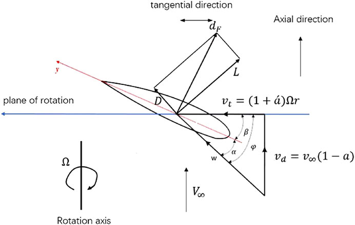
FIGURE 1. Blade element velocity triangles and force vector diagrams.
In Figure 1, D is the drag force; L is lift force;
Axial induced factor a and tangential induced factor
where v is the wind speed before the wind wheel, and vt is the tangential velocity of the airflow at the wind wheel.
The axial induced velocity of the airflow is as follow:
The tangential induced velocity of the airflow is as follows:
The relative velocity of airflow synthesis is as follows:
The inflow angle of airflow is as follows:
According to the conservation of energy and momentum, the thrust and torque received by the wind wheel are shown as follows:
Based on the blade element theory, the thrust and torque of the wind wheel are respectively shown as follows:
where CL is the lift coefficient of airfoil, CD is the drag coefficient of airfoil, which can be generally obtained by referring to the airfoil data table.
When evaluating, first initialize a and
After obtaining the inflow angle, the airfoil’s angle of attack can be determined by the following formula:
Further, lift coefficient CL and drag coefficient CD are obtained by referring to airfoil data table. Then a and
Potential flow method
Basic assumptions: 1) the floating platform is a rigid body and its elastic deformation is ignored; 2) The waves acting on the floating foundation are micro amplitude waves, and the nonlinear effects such as wave breaking, shallow water effect; 3) The floating foundation makes micro amplitude simple harmonic vibration near its equilibrium position, which simplifies the force and motion of the floating foundation under the action of waves into a linear problem, which is applicable to the superposition principle (Merz, et al., 2009; Pu et al., 2012; Ning, et al., 2018; Yu et al., 2020; Ma et al., 2022; Yu et al., 2022). Considering only the first-order velocity potential, the frequency domain motion equation of floating platform under the action of inertia force, damping force, hydrostatic restoring force, mooring system restoring force and first-order wave force is established according to the principle of dynamic force balance:
where ω is the frequency of incident wave; M is the inertia matrix of floating foundation; A(ω) is the additional mass matrix related to frequency is composed of additional mass Aij; B(ω)p is the frequency dependent potential flow damping matrix; Bv is the linear damping matrix related to fluid viscosity; C is hydrostatic restoring stiffness matrix; Ce restoring stiffness matrix of mooring system; β is the propagation direction of incident wave; X (x, β) is the motion matrix of floating foundation; F (ω, β) is the wave excitation force matrix, which is composed of wave excitation force acting on large-scale structure and inertial force and drag force acting on small-scale structure; i is an imaginary number unit, which satisfies
For various marine engineering structures, the wave loads they are subjected to can be classified as drag force, inertia force and diffraction force. For different structures, the proportion of various wave-induced load components is different, so the wave load should be calculated reasonably according to the structure size. When calculating the wave loads acting on the floating platform, since the platform of floating offshore wind turbine is usually a combination of two scales, such as large-scale buoy and small-scale circular pipe, this paper combines Morison equation and potential flow theory to calculate the wave loads on the floating platform. For smaller structures (diameter is generally less than 1/5 of wave wavelength), the existence of structures has no significant influence on wave motion. The main effects of waves on structures are viscous effect and additional mass effect. In this case, the Morison equation can be used to calculate the wave forces. The transverse wave load dFih per unit length is:
where
For the wave load of large-scale structures (the diameter is generally greater than 1/5 of the wavelength), the potential flow theory is usually used to calculate the velocity potential. In the basin where the floating platform is located, the velocity potential consists of three parts consists of three parts: undisturbed incident velocity potential ϕω, diffraction velocity potential of the floating platform ϕd and radiation velocity potential ϕj which is caused by the movement of the floating platform, that is:
The fluid in the basin near the ocean structure is an ideal fluid, then the problem of solving the velocity potential of wave field can be simplified to solving the Laplace equation with corresponding fluid boundary conditions. The wave field calculation of irregular structures in offshore engineering needs to be realized by numerical method. Usually, the boundary element method is used to calculate the linear wave frequency response of large-scale structures in regular waves. The specific calculation process is as follows (Qu, et al., 2013): 1) the wet surface of the platform is divided into several grids to form several panel elements. Based on the source sink distribution method, it is assumed that the surface sources with equal strength are distributed on each panel element; 2) Combined with Laplace equation and the boundary conditions of radiation potential and diffraction potential, the intensity of surface source is solved; 3) The intensity of the surface source is integrated along the wet surface grid to calculate the radiation potential and diffraction potential respectively, so as to determine the velocity potential in the flow field.
Reference data of OO-Star wind floater semi DTU-10MW
The model used in this paper is OO-Star Wind Floater Semi DTU-10MW ( 2016). The upper part of this floating wind turbine model is a DTU-10MW wind turbine model, which is a reference wind turbine model designed by the Technical University of Denmark in 2013. On the other hand, the OO-STAR semi-submersible platform is used in the lower part of the floating wind turbine model. The OO-Star Wind Floater Semi DTU-10MW floating offshore wind turbine model is shown in Figure 2 below.
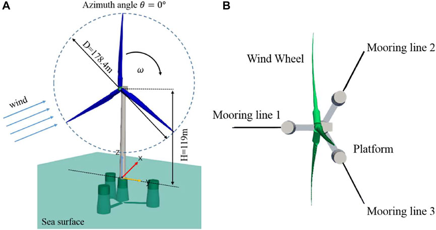
FIGURE 2. Geometry of OO-Star Wind Floater Semi DTU-10MW and mooring system: (A) geometry model; (B) mooring system.
The DTU 10-MW wind turbine is a conventional three-blade upwind variable-speed variable-blade-pitch-to-feather-c*ontrolled turbine. Its rotor diameter is about 178.4 m and the hub height is nearly 119 m. The rated wind speed is 11.4 m/s. Under the rated wind speed, the rotor speed is 9.6 rpm and the power is 10 MW.
The blades are separated into 38 blade elements and the structure of the blades used in BEM can refer to Wandji et al. (2016). Additionally, the radius of the tower top is 5.5 m and the radius of the tower bottom is 8.3 m, which is linearly distributed along the tower.
The OO-Star Semi Floating Substructure is a semi-submersible platform consisting of a star-shaped base buoy that connects a central column and three outer columns. All pillars have a cylindrical upper part and a tapered lower part. The distance between the central column and the outer column is 37 m. The horizontal buoy element connecting the columns is 16 m wide and 7 m high. The total mass of the platform, including ballast, is 21,709 tons.
The mooring system of DTU-10MW semi-submersible floating wind turbine is composed of three mooring lines, each of which is distributed centrally at a horizontal angle of 120°. The properties of the DTU-10MW model, structural attributes of the platform and specific mooring system parameters are shown in Table 1.
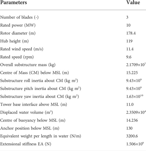
TABLE 1. Properties of DTU -10 MW wind turbine and OO-Star Semi floating substructure.
Model validation
Thrust and power
To examine the accuracy of different wind speeds, the thrust and power are computed and compared with the value computed by CFD method and HWACStab2 code (Wandji, et al., 2016), which are shown in Figure 3. The results agree with CFD and HWACStab2 code excellently for the wind speeds from 5 m/s to 25 m/s. In this verification part, the degree of freedom of platform movement is turned off to ensure that the influence caused by platform movement is excluded.

FIGURE 3. The thrust and power under different wind speeds: (A) thrust; (B) power.
Free decays
The free decays of OO-Star semi-submersible platform model are carried out to verify the model. An initial displacement is given for each degree of freedom (DOF) of the floating offshore wind turbine system, and then it is allowed to decay freely to the equilibrium position. An initial displacement of 15 m is given for the surge and heave motions, and an initial deflection angle of 10° is given for pitch and yaw motions. In the free decays simulation process of the floating offshore wind turbine system, the wind turbine is always in the shutdown condition with no incoming wind and wave.
The free decays of the floating offshore wind turbine system are numerically simulated by using FAST code, and the time series responses of the platform movement are obtained, and they are shown in the Figure 4. The natural frequencies of each degree of freedom are obtained by Fourier transform of the time series response.
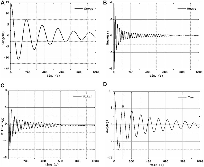
FIGURE 4. The free decay of the OO-Star platform: (A) Surge; (B) Heave; (C) pitch; (D) Yaw.
The natural frequencies obtained are compared with the reference value in the report of DTU (Wandji, et al., 2016) in Table 2. The errors are all smaller than 2% which means the results are in good agreement with the reference data.
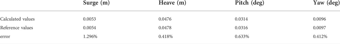
TABLE 2. The natural frequencies of the free decays.
Motion characteristics and aero-elastic responses of DTU-10MW FOWT
In this section, the motion characteristics and aeroelastic responses of the DTU-10MW Turbine under the action of wind and wave coupling are studied. By comparing with the output power and thrust of the fix wind turbine, the influence of the floating platform motions on the aeroelastic response of the upper turbine is analysed. The motion characteristics and elastic response of the floating offshore wind turbine are calculated under different wind and wave combination conditions, and the effects of wind and wave are summarized. Finally, the dynamic response of the floating offshore wind turbine with the wind-wave Misalignment is discussed and analysed, and the effect of the incident angle of wave on the motion responses of the floating wind turbine is analysed.
The coupling effect of wind and wave on offshore floating wind turbine in actual operation is mainly considered. The motion characteristics and aeroelastic response of the fan under the coupling action of wind and wave are studied by selecting the combined wind and wave loads with different parameter characteristics. As shown in Table 3, uniform wind load is selected for wind load; as for hydrostatic load, regular wave load and irregular wave load are selected for wave load, and JONSWAP spectrum is selected for irregular wave. DLC1 ∼ DLC3 (Design Load Case) conditions are selected to study the effect of wind speed on the motion characteristics and the aeroelastic response of blades under still water hydrostatic load. DLC4 ∼ DLC6 are selected to study the effect of different significant wave heights and wave cycles on the motion characteristics of the turbine under regular waves. DLC7 is selected to study the motion response and aerodynamic load characteristics of floating wind turbine under irregular wave, and the effect of wave load form is analysed by comparing with the motion response of the wind turbine under the regular wave.
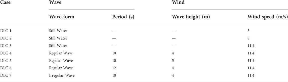
TABLE 3. The list of the cases.
Compared with the onshore wind turbine, the floating offshore wind turbine is larger in size which means it needs to bear greater aerodynamic load during operation. What’s more is that the complex aerodynamic loads acting on the wind wheel will have a great impact on the motion of the floating platform, which in turn will affect the relative inflow conditions of the upper turbine. Therefore, the motion response calculation of the floating offshore wind turbine is very challenging. All calculation examples in this section adopt the elastic model, that is, the aeroelastic responses of the wind turbine are considered, and the six degrees of freedom of the platform are considered in the simulation of the floating offshore wind turbine.
Effect of the wind load
Motion characteristic
In this section, the corresponding platform motions under different wind speed conditions are calculated, and then the influence of different wind speeds on the motion response of the whole floating wind turbine under hydrostatic load is obtained. The following Figures 5A–F show the time history curve of the six DOFs motion of the floating platform under different wind speeds, in which the wind speeds are set as 5 m/s, 8 m/s and 11.4 m/s respectively.
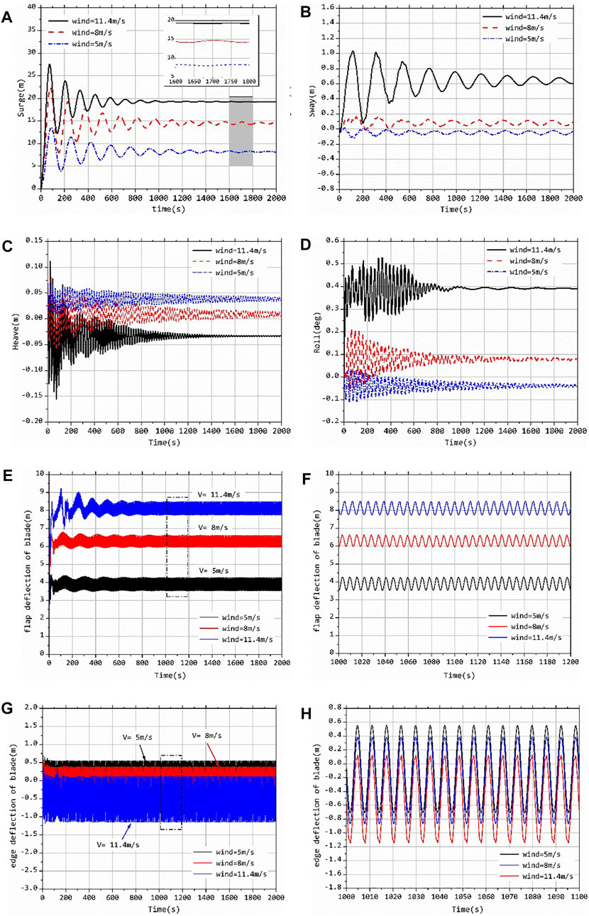
FIGURE 5. Motions of floating platform and deflection under different wind speeds: (A) Surge; (B) Sway; (C) Heave; (D) Roll; (E) pitch; (F) Yaw; (G) flap deflection; (H) partial enlargement in flap deflection.
From the Figure 5, the aerodynamic loads of the turbine make the platform produce a six DOFs motion response, in which surge motion and pitch motion are the main motion forms. Under the action of the aerodynamic thrust generated by the wind wheel, the platform will produce very obvious surge motion and pitch motion (see Figures 5A,E); The aerodynamic load and hydrodynamic load will cause the platform to produce corresponding micro amplitude roll and sway motion (see Figures 5B,D); Heave motion and yaw motion are affected by other motions, resulting in coupling response and fluctuation. Below the rated wind speed, the corresponding displacement response value of each DOF increases with the increase of wind speed, and the surge motion is the most obvious, which indicates that the equilibrium position of each DOF motion of the platform is obviously affected by the wind load under the action of uniform wind. In addition, it is worth noting that with the increase of inflow wind speed, the frequency of platform surge motion increases, beside the time required for platform motion to stabilize under the wind speed of 11.4 m/s is shorter. This is because under the action of wind speed of 11.4 m/s, the equilibrium position of platform surge displacement is largest, the tension degree of mooring lines is larger, and the restoring force provided is larger, which affects the frequency of surge movement. Because of this, when the wind speed increases, the vertical component of the tension provided by the mooring lines increases, resulting in a negative shift in the equilibrium position of the platform heave.
Aero-elastic response
Figures 5G,H have shown the time history curve of blade tip deflection under DLC1 ∼ DLC3 working conditions which are consistent with Table 3. As can be seen from the figure that the vibration dominant frequency of blade tip deflection is consistent with the rotation frequency of wind turbine, indicating that the rotation of wind turbine will cause the periodic change of aerodynamic force and then stimulate the periodic change of blade elastic deformation response. Besides, it can be seen that the surge motion of the floating platform will cause corresponding low-frequency fluctuation of blade tip deflection in the range of 0 ∼ 1,000 s in Figure 5G, and the surge motion amplitude of the platform is the largest under the wind speed of 11.4 m/s, so the corresponding blade tip deflection fluctuation is also the largest. When the platform motions are relatively stable, the vibration of blades in the direction of the flapwise and the edgewise becomes stable, which is the same as the blades of onshore wind turbine. The inflow wind speed is still the main factor affecting the mean value of blade vibration, but it has little influence on the amplitude of vibration.
Effect of the wave load
Motion characteristic under regular wave
In this section, the simulation and calculation are carried out for the working conditions of DLC4 ∼ DLC6 which have shown in Table 3. The motion responses of the floating wind turbine system under the combined action of regular wave and uniform wind are calculated. The whole simulation time is 2000 s, and 1,000 s ∼ 1,050 s of the stable section is taken as the output result. The six DOFs motions of floating offshore wind turbine system under corresponding working conditions of DLC4 ∼ DLC6 are given in Figure 6 below.
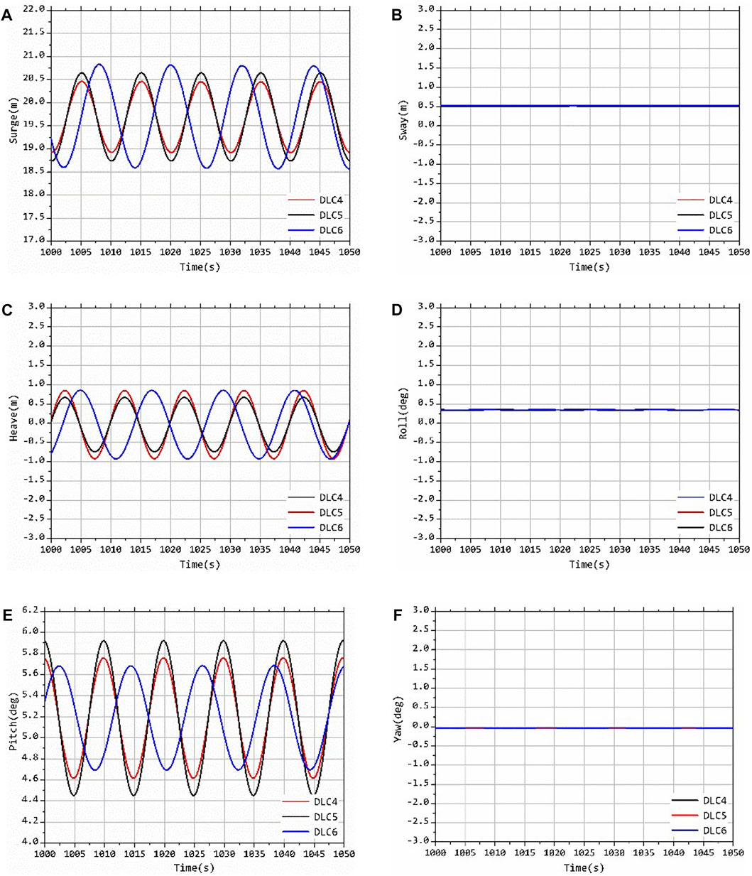
FIGURE 6. Motions of the platform under the regular wave: (A) Surge; (B) Sway; (C) Heave; (D) Roll; (E) pitch; (F) Yaw.
When the regular wave flows into the front, the motion response of the floating offshore wind turbine produce surge, pitch motion and heave motion caused by the coupling effect. Because the wave and wind load flow directions are perpendicular to the rotation plane of the wind turbine, that is, consistent with the surge direction, the surge motion amplitude response of the floating offshore wind turbine system is the largest in these simulations, and the large-scale surge motion of the platform causes the pitch motion and the heave motion; For the floating platform, the load is very small in the sway, roll and yaw motion directions, so the movement is relatively stable. It can be seen from Figure 6 that after changing the wave conditions, the equilibrium position of each degree of freedom motion is basically the same, but the motion amplitude changes significantly.
It can be seen from Figure 6 that under the action of regular wave and uniform wind, the changes of wave period and significant wave height have a great impact on the surge, pitch and heave motion of the floating offshore wind turbine system. The amplitude of surge, pitch and heave will increase with the increase of significant wave height. The increase of wave period will obviously increase the amplitude of surge motion, and the amplitude of heave motion will increase accordingly, but it has little effect on the pitch motion. It can be seen that for the floating offshore wind turbine system, the wind load mainly determines the mean value of each degree of freedom motion, while the wave load mainly affects the amplitude of each degree of the freedom motion.
Motion characteristic under irregular wave
Compared with the regular wave load in the ideal state, the irregular wave load is more accord with the real wave load environment at sea. In this section, the irregular wave incident load is selected based on the typical sea conditions in the South China Sea, and the JONSWAP spectrum is selected as the wave spectrum. The DLC7 working condition is set in Table 3 for specific parameters. Figure 7 shows the comparison results between the frequency spectrum of the wave elevation and the target spectrum used for calculation in the process of wave load simulation. The power spectrum of irregular waves simulated in this paper is in a good agreement with the target spectrum, which shows that the method in this paper can simulate the sea state of irregular waves well, and the simulation setting of irregular wave load is correct.
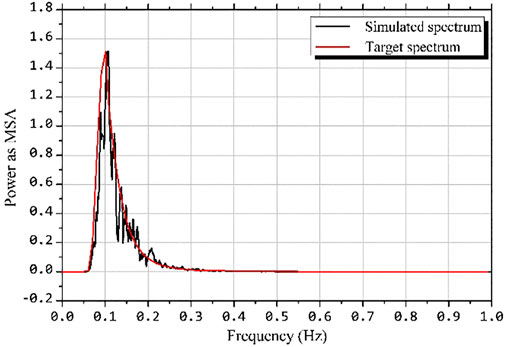
FIGURE 7. Comparison between simulated wave elevation frequency spectrum and target spectrum.
Figure 8 shows the motion response of the floating offshore wind turbine in the surge, heave and pitch directions under irregular wave load and the time history curve of the wave elevation at the center of the platform. It can be seen from the figure that the surge, heave and pitch motion trends of the floating offshore wind turbine are very consistent, and the change trend is basically the same as that of the wave elevation. There is an obvious sudden change in amplitude of the surge, pitch and heave motion of the floating fan in the period of 1,200 s–1,250 s. It is found that the time history curve of wave elevation corresponds to the maximum change of wave load at this time. This shows that under the action of irregular waves, the motion response of the platform is directly related to the change of waves, that is, the motion response of each degree of freedom increases with the increase of wave height. The equilibrium positions of heave, heave and pitch motion of the platform under this group of working conditions are 19.6926 m, −0.0361 m and 5.187° respectively. Compared with the motion response of the platform under the action of regular wave under DLC4 working condition, it is found that the equilibrium position of each degree of freedom motion is basically the same, and the reason for the slight difference is the slight difference of aerodynamic load caused by the different motion of the platform. It shows again that the main factor is the wind load determining the balance position of the floating offshore wind turbine system under the wind-wave coupling, and the influence of the wave load on the balance position is very small.
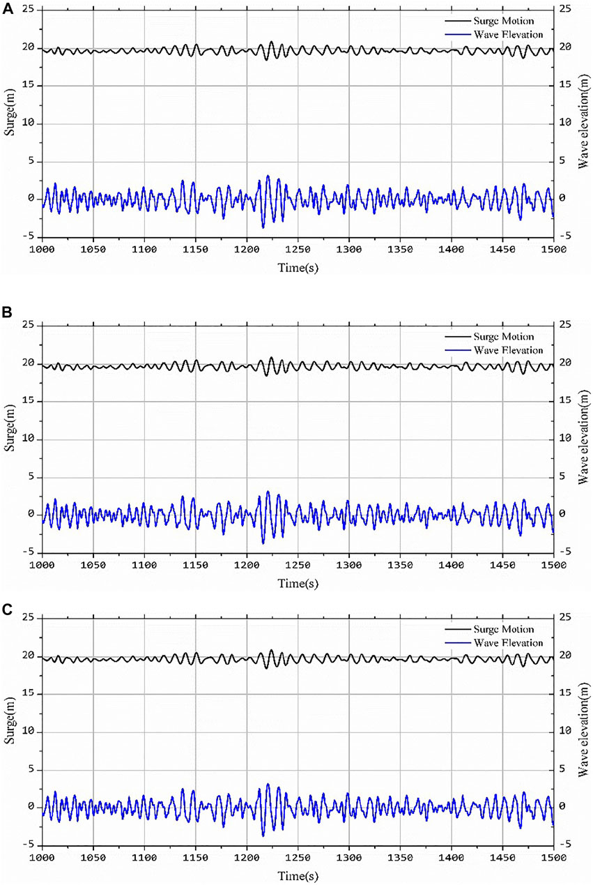
FIGURE 8. Motion response and wave height time history curve of floating fan under the irregular wave: (A) Surge; (B) Heave; (C) Pitch.
Aero-elastic response
The blade elastic deformation is mainly determined by the aerodynamic load acting on the blade. Under the action of regular wave, the blade needs to bear periodic aerodynamic load, so the blade will produce corresponding elastic deformation response. Figure 9 shows the blade flap deflection and edge deflection responses of the blades under DLC4 working condition and the corresponding frequency domain response values.
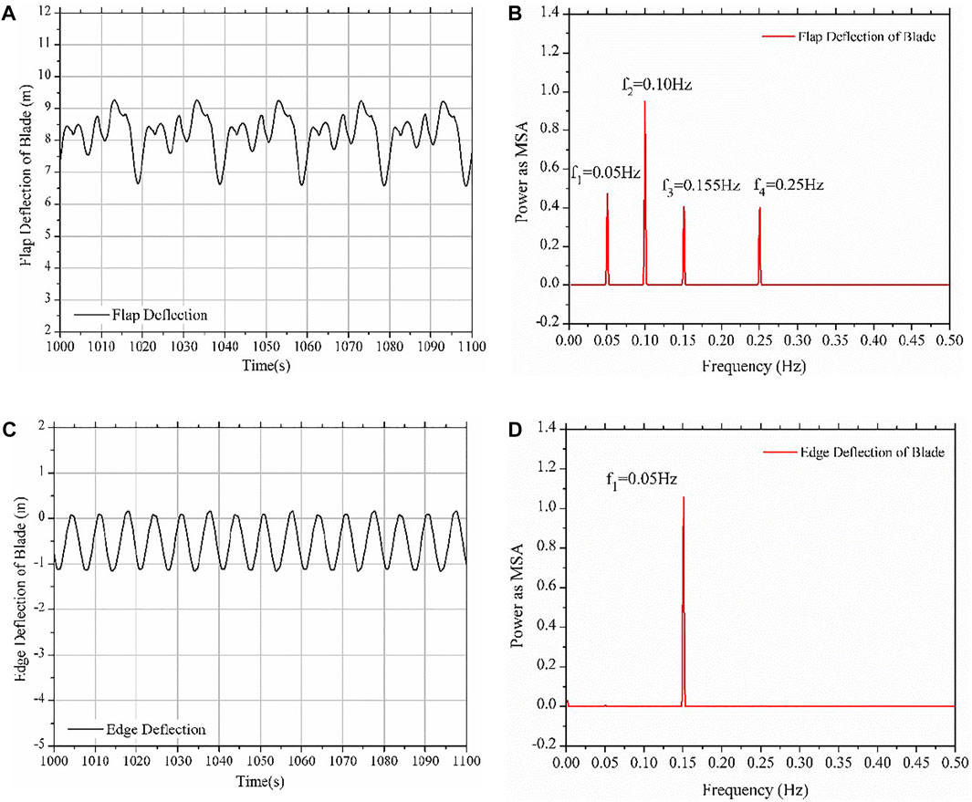
FIGURE 9. Deflections under different regular waves: (A) the time history of the flap deflection; (B) the power spectrum of the flap deflection; (C) the time history of the edge deflection; (D) the power spectrum of the edge deflection.
It can be seen from Figure 9 that under the action of regular wave, the blade has periodic deformation response in the flapwise direction, which is different from the displacement response of onshore fixed wind turbine. Under the action of regular wave, there is a very obvious low-frequency vibration response in the flapwise direction of blade. The frequency of blade vibration can be obtained by Fourier transform of the time history response of blade flap deflection in the stable stage. There are four frequencies: f1 = 0.05 Hz, f2 = 0.10 Hz, f3 = 0.155 Hz and f4 = 0.25 Hz.
Where f1 = 0.05 Hz corresponds to one-third rotor rotation frequency, which is caused by the tower shadow effect; f2 = 0.10 Hz corresponds to wave frequency; f3 = 0.155 Hz corresponds to rotor rotation frequency; and f4 = 0.25 Hz corresponds to the first-order vibration frequency of the tower, which shows that wave load, rotor rotation speed and vibration response of the tower will have a great impact on the vibration in the flapwise direction of the blade. On the other hand, the displacement amplitude of the blade in the edge direction is small, and the vibration form is mainly simple harmonic vibration. The vibration frequency f in the edge direction also can be obtained by Fourier transform: f3 = 0.155 Hz, which is consistent with the rotation frequency of the rotor. It shows that the vibration in the edge direction of the blade under the action of regular wave is mainly related to the rotation frequency of the rotor itself, but has little influence on the wave load frequency, tower vibration and other factors. The reason for the inconsistency between the vibration forms in the flapwise and edgewise directions of the blade is the inconsistency between the loading direction of the aerodynamic load and the stiffness of the blade in both directions.
Effect of the wind-wave misalignment
In natural conditions, the environmental load is complex and changeable. When wind wave coupling acts on the floating offshore wind turbine system, there is often the included angle of wind and wave, which is also known as the phenomenon of wind wave misalignment. Relevant research shows that under the high wind speed, there will be a small angle between wind and waves, while under low wind speed, the wind and wave load is prone to a large angle (Fischer, et al., 2011). The statistical results show that the angle between wind and waves is usually within 0 ∼ 60° under the wind wave coupling, and the probability of exceeding 60° is less than 5% (Kuhn, 2001). It is clearly pointed out in the design specification manual of floating offshore wind turbine (Veritas, 2013) that the existence of wind wave angle will have a negative impact on the movement of turbine, and the existence of wind wave load angle should be considered in the design condition of floating offshore wind turbine. Therefore, it is necessary to study the effect of the wind - wave misalignment.
In this section, the influence of wave incidence angle on the six DOFs motion responses of floating fan is studied by changing the wave incidence angles. Considering that the wind turbine will control the yaw angle of the wind turbine through the control system to make the wind turbine face the incoming wind load to reduce the yaw moment of the wind turbine, the wind load is set perpendicular to the rotation plane of the wind turbine in the whole simulation process. The uniform inflow wind load is adopted, and the wind speed is set as the rated wind speed of 11.4 m/s. Regular wave loads are adopted for waves, and the incident angles of waves are set to -180 ∼ +180°, one group is taken every 15°. The wind-wave load setting is shown in Figure 10.
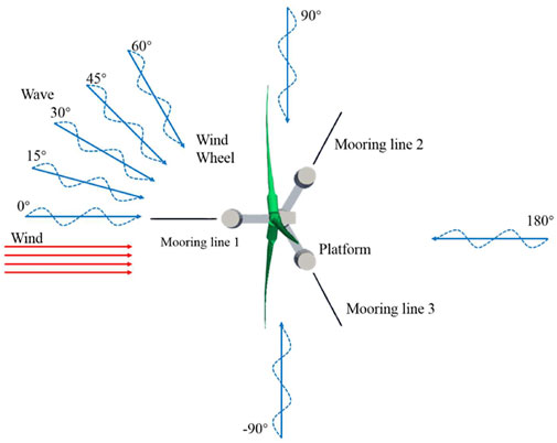
FIGURE 10. Wind-wave load setting.
Figure 11 below shows the six DOFs motion response of the floating offshore wind turbine system at wave incident angle of 0–60°, and the stable section after 1,000 s is taken as the output result.
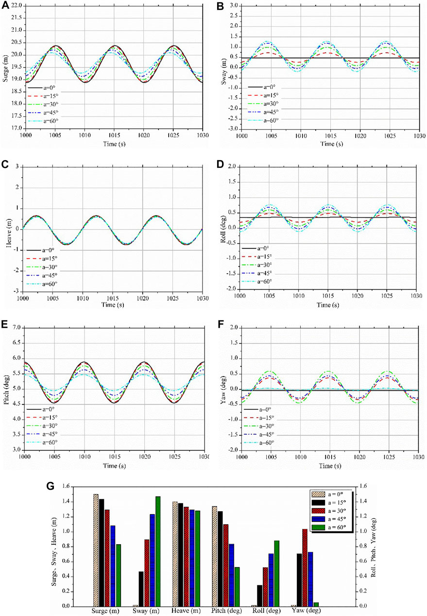
FIGURE 11. Motions of floating platform under different wave incidence angles: (A) Surge; (B) Sway; (C) Heave; (D) Roll; (E) pitch; (F) Yaw; (G) Motion amplitude.
It can be seen from Figure 11 that the incident angle of waves does not significantly change the equilibrium positions of the respective degrees of freedom motion, but it has a significant influence on the amplitudes of the motion of the platform. For the surge motion, the amplitude decreases slightly with the increase of wave direction angle α and the phase changes slightly. For the sway motion, the amplitude of motion oscillation increases significantly with the increasing of the incident angle α. For heave motion, the change of wave direction angle α has very little effect on it. For roll motion, the amplitude of motion oscillation increases obviously with the increase of wave direction angle α. Similar to the rolling motion, for pitch motion, the amplitude of motion oscillation decreases significantly with the increasing of the wave direction angle α, which is mainly related to the decreasing of the amplitude of the surge motion. The variation of the wave incident angle shadow is slightly different for the yaw motion. The amplitude of the yaw motion increases with the increasing of the wave direction angle in the range of 0 ∼ 30° and decreases with the increasing of the wave direction angle in the range of 30 ∼ 60°. This is because the mooring lines are arranged symmetrically with respect to the center of 120°. When the angle of incidence of wave is 0 and 60°, the wave load is facing the direction of No.1 and No.3 mooring lines. At this time, the tension of the mooring lines is the greatest, which restrains the swaying motion of the platform to a certain extent. This shows that the yaw motion of the floating offshore wind turbine is not only affected by the form of wave load of wind load, but also related to the layout of the platform and mooring system. Table 4; Figure 11G show the amplitudes of the motions of the floating offshore wind turbine system when wave directions are set between 0 and 60°.
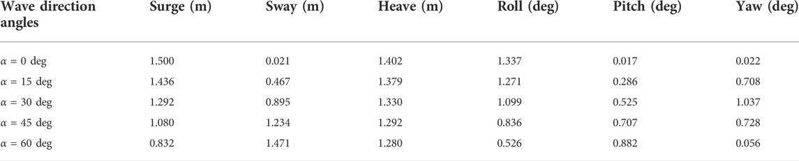
TABLE 4. Motion amplitudes of floating offshore wind turbine under different wave direction angles.
Conclusion and discussions
The purpose of the present research is to study the motion characteristics of floating offshore wind turbine under the wind and wave coupling load. Therefore, FAST code is used to model and calculate the DTU-10MW semi-floating offshore wind turbine under different wind and wave combination conditions. Some results are summarized as follows:
The motion of floating offshore wind turbine system is affected by both wind load and wave load, and the wind load determines the mean value of each motion, while the wave load affects the amplitude of each motion.
When the inflow direction of wind and wave load is directly ahead, the floating offshore wind turbine mainly presents the motion forms of surge, heave and pitch motion.
The increasing of the wave incidence angle will reduce the amplitude of surge, pitch and heave motion response of floating offshore wind turbine, and will increase the amplitude of sway and roll response. The maximum yaw motion response occurs when the included angle of wind and wave is 30°.
The potential flow method is used to calculate the motion of the platform in the model. The results show that it is accurate enough, but there are also some limitations. For example, the treatment of the viscous effect of water is not considered. Further research is needed to improve the model and make it more widely accepted.
Data availability statement
The raw data supporting the conclusion of this article will be made available by the authors, without undue reservation.
Author contributions
BW made the computations, YL conducted the data analysis, SG drew some pictures, KS did the comparison and conducted the data analysis, ZH made the computations and the proofreading, XZ wrote the whole papers.
Funding
This work is supported by the National Natural Science Foundation of China (Nos. 51739001, 52071301, 51909238), Zhejiang Provincial Natural Science Foundation of China (LHY21E090001), Natural Science Foundation of Heilongjiang Province in China (LH2020E071), the Open Fund of the Key Laboratory of Far-shore Wind Power Technology of Zhejiang Province (ZOE20200007).
Acknowledgments
The last authors acknowledge the support of Professor Qingwei Ma at City, University of London for the research topic. We all acknowledge the Frontier Editorial Team and Editor Professor MP for their professional handling of the manuscript, and two dedicated referees who provided very constructive and insightful comments to significantly improve the quality of the work.
Conflict of interest
BW, SG, and KS were employed by the company Powerchina Huadong Engineering Corporation Limited.
The remaining authors declare that the research was conducted in the absence of any commercial or financial relationships that could be construed as a potential conflict of interest.
Publisher’s note
All claims expressed in this article are solely those of the authors and do not necessarily represent those of their affiliated organizations, or those of the publisher, the editors and the reviewers. Any product that may be evaluated in this article, or claim that may be made by its manufacturer, is not guaranteed or endorsed by the publisher.
References
Cao, H. (2009). Study on the hydrodynamic performance of semi-submersible floating foundation of offshore wind turbine. Ph.D. Thesis. Tianji: Tianjin University.
Dong, Y. Q. (1991). Ship wave external load and hydroelasticity, 6. Tianjin: Tianjin University Press.
Fischer, T., Rainey, P., Bossanyi, E., and Kuhn, M. (2011). Study on control concepts suitable for mitigation of loads from misaligned wind and waves on offshore wind turbines supported on monopiles. Wind Eng. 35 (5), 561–573. doi:10.1260/0309-524X.35.5.561
Gaumond, M., Réthoré, P.-E., Ott, S., Peña, A., Bechmann, A., and Hansen, K. S. (2014). Evaluation of the wind direction uncertainty and its impact on wake modeling at the Horns Rev offshore wind farm. Wind Energy (Chichester). 17, 1169–1178. doi:10.1002/we.1625
Huijs, F., Bruijn, R., and Savenije, F. (2014). Concept design verification of a semi-submersible floating wind turbine using coupled simulations. Energy Procedia 53, 2–12. doi:10.1016/j.egypro.2014.07.210
Jonkman, J. M., and Matha, D. (2011). Dynamics of offshore floating wind turbines-analysis of three concepts. Wind Energy (Chichester). 14, 557–569. doi:10.1002/we.442
Kuhn, M. (2001). Dynamics and design optimisation of offshore wind energy conversion systems. Ph.D. Thesis. Netherlands: Delft University of Technology.
Latha, S., and Vengatesan, V. (2013). Hydrodynamic response of a stepped-spar floating wind turbine: Numerical modelling and tank testing. Renew. Energy 52, 160–174. doi:10.1016/j.renene.2012.09.063
Lo, K. (2014). A critical review of China's rapidly developing renewable energy and energy efficiency policies. Renew. Sustain. Energy Rev. 29, 508–516. doi:10.1016/j.rser.2013.09.006
Ma, Y., Hu, C., and Li, L. (2022). Hydrodynamics and wake flow analysis of a Pi-type vertical axis twin-rotor tidal current turbine in surge motion. Ocean. Eng. 224, 108625. doi:10.1016/j.oceaneng.2021.108625
Madjid, K., Meissonnier, Q., Gao, Z., and Moan, T. (2011). Hydroelastic code-to-code comparison for a tension leg spar type floating wind turbine. Mar. Struct. 24, 412–435. doi:10.1016/j.marstruc.2011.05.006
Madjid, K. (2013). Modeling aspects of a floating wind turbine for coupled wave wind-induced dynamic analyses. Renew. Energy 53, 299–305. doi:10.1016/j.renene.2012.12.006
Merz, K. O., Moe, G., and Gudmestad, O. T. (2009). A Review of hydrodynamic effects on bottom - fixed offshore wind turbines. Honolulu: ASME 28th International Conference on Ocean.
Ning, D. Z., Zhou, Y., and Zhang, C. W. (2018). Hydrodynamic modeling of a novel dual-chamber OWC wave energy converter. Appl. Ocean Res. 78, 180–191. doi:10.1016/j.apor.2018.06.016
Pu, J. H., Cheng, N. S., Tan, S. K., and Shao, S. (2012). Source term treatment of SWEs using surface gradient upwind method. J. hydraulic Res. 50, 145–153. doi:10.1080/00221686.2011.649838
Qu, J. S., Guan, Y. F., and Lu, Y. X. (2013). Analysis of dynamic rensponse of jacket platform structure based on SESAM. J. Jiangsu Ship 30 (1), 1–5. doi:10.3389/fenrg.2020.0004
Shi, Y., Li, S., Chen, H., He, M., and Shao, S. (2018). Improved SPH simulation of spilled oil contained by flexible floating boom under wave–current coupling condition. J. Fluids Struct. 76, 272–300. doi:10.1016/j.jfluidstructs.2017.09.014
Veritas, D. N. (2013). Design of floating wind turbine structures. Oslo: Det Norske Veritas As. DNV-OS-J103-2013.
Wandji, W. N., Natarajan, A., and Dimitrov, D. (2016). Development and design of a semi-floater substructure for multimegawatt wind turbines at 50+ m water depths. Ocean. Eng. 125 (1), 226–237. doi:10.1016/j.oceaneng.2016.07.021
wind.nrel (2003). NWTC design codes (FAST). Available at: http://wind.nrel.gov/designcodes/simul-ators/OpenFAST (accessed on September 20, 2021).
Yu, Z. L., Zhu, C. C., Tan, J. J., Song, C. S., and Wang, Y. (2022). Fully-coupled and decoupled analysis comparisons of dynamic characteristics of floating offshore wind turbine drivetrain. Ocean. Eng. 247, 110639. doi:10.1016/j.oceaneng.2022.110639
Yu, Z. Y., Hu, Z. H., Zheng, X., Ma, Q. W., and Hao, H. B. (2020). Aeroelastic performance analysis of wind turbine in the wake with a new elastic actuator line model. Water 12 (5), 1233. doi:10.3390/w12051233
Zhang, R. Y., Tang, Y. G., Hu, J., Ruan, S., and Chen, C. (2013). Dynamic response in frequency and time domains of a floating foundation for offshore wind turbines. Ocean. Eng. 60, 115–123. doi:10.1016/j.oceaneng.2012.12.015
Keywords: floating offshore wind turbine, coupling action, coupling action of waves and winds, motion, aero-elastic responses
Citation: Wang B, Li Y, Gao S, Shen K, Hu Z and Zheng X (2022) Motion characteristics and aero-elastic responses of floating offshore wind turbine under coupling action of waves and winds. Front. Environ. Sci. 10:965334. doi: 10.3389/fenvs.2022.965334
Received: 09 June 2022; Accepted: 18 July 2022;
Published: 29 August 2022.
Edited by:
Manish Pandey, National Institute of Technology Warangal, IndiaReviewed by:
Chongwei Zhang, Dalian University of Technology, ChinaYong Ma, Sun Yat-sen University, China
Copyright © 2022 Wang, Li, Gao, Shen, Hu and Zheng. This is an open-access article distributed under the terms of the Creative Commons Attribution License (CC BY). The use, distribution or reproduction in other forums is permitted, provided the original author(s) and the copyright owner(s) are credited and that the original publication in this journal is cited, in accordance with accepted academic practice. No use, distribution or reproduction is permitted which does not comply with these terms.
*Correspondence: Xing Zheng, emhlbmd4aW5nQGhyYmV1LmVkdS5jbg==