 Yanjun Zhang
 Jiayuan Kong2
94% of researchers rate our articles as excellent or good
Learn more about the work of our research integrity team to safeguard the quality of each article we publish.
Find out more
ORIGINAL RESEARCH article
Front. Environ. Sci., 12 July 2022
Sec. Environmental Informatics and Remote Sensing
Volume 10 - 2022 | https://doi.org/10.3389/fenvs.2022.915645
Ground fissures caused by underground coal seam mining easily result in secondary geological disasters and destroy the ecological environment, which seriously impacts the production and life of mining areas and residents. The traditional monitoring methods, such as manual measurement and satellite monitoring, have their disadvantages. Therefore, it is urgent to develop a large-scale monitoring technology for ground fissures and study its development law. In this article, we analyzed the distribution characteristics of ground fissures based on the low-altitude UAV remote sensing images and combined them with field investigation as validation. Moreover, we introduced the particle flow theory to study the development law and formation mechanism of ground fissures. This article takes the 8092 working face of a mine in Ordos City as the study area. The results showed that the accuracy rate of ground fissures based on the visual interpretation of UAV images was 95%. The ground fissures were mainly distributed near the stopping line and the groove of the working face. The plane forms of ground fissures were mainly two types: the linear type and arc type, and the location relationship can be divided into the parallel type and bifurcation type. The types of ground fissures were the tensile type and step type. Whether the upper and lower parts of the key strata were broken simultaneously is the root cause of tensile ground fissures and step ground fissures. The stability of the overlying strata had a significant influence on the change of abutment pressure above the goaf. The process of surface movement and deformation can be divided into three stages: tensile failure of the slope bottom, traction failure of the slope body, and sliding failure of the slope top. In addition, the zero point of the surface horizontal movement value and the maximum surface subsidence were not in the center of the goaf. Due to the horizontal slip of the downhill direction in the horizontal movement on the surface, the value of the downhill direction subsidence was zero. However, the value of the horizontal movement was not zero, and there was even a large horizontal movement. In conclusion, the research results can provide a useful reference for the rapid monitoring of large-scale geological disasters caused by underground coal seam mining and the application of the particle flow theory.
With the growing global demand for energy, coal resources have become the second largest energy in global energy consumption. According to the relevant statistics, global production in 2020 exceeded 750 million tons (IEA, 2021). After coal is mined, the original stress equilibrium state in the surrounding rock strata is destroyed, and the movement of overlying strata from bottom to top causes surface subsidence (Zhang and Wang, 2014; Yu and Guo, 2016; Zhang et al., 2021). Large-scale surface subsidence will lead to the ground fissures, especially in loess and gully regions. Due to the low vegetation coverage rate and severe soil erosion, ground fissures formed by coal mining often cause geological disasters such as landslides and collapses. In particular, when the ground fissures are connected with the goaf, safety accidents such as air leakage and water inrush will occur, which seriously threaten the safety of people’s lives and property (Lian et al., 2020a; Yang et al., 2022; Zhang et al., 2020; Liu et al., 2013). Therefore, the large-scale investigation of ground fissures caused by mining subsidence and study of its development law has become particularly important.
In order to obtain dynamic information of ground fissures, the traditional method was based on field measurement by total station, tape, and GPS (Lian et al., 2020b; Li et al., 2017). The advantage of field measurement is the high accuracy. However, if there are too many ground fissures caused by coal mining, it is time-consuming for the process of field measurement (Peng et al., 2016). Some scholars have applied satellite remote sensing images to extract ground fissures, but there are obvious limitations in spatial and temporal resolution, which cannot meet the high precision needs (Li, 2007; Zhang et al., 2019). With the continuous development of UAV photogrammetry technology, it is widely used to study geological disasters. The high-resolution images of the mining area can be quickly obtained through the UAV system, and the ground fissures can be extracted by visual interpretation with the generated DOM (Digital Orthophoto map). The accuracy can reach the centimeter level (Zhang et al., 2017; Gao et al., 2018; Lian et al., 2020c). For example, Zhang et al. (2017) and Gao et al. (2018) realized the monitoring of surface subsidence in mining areas by the UAV remote sensing technology, which made up for the deficiency of the traditional conventional measurement technology; Lian et al. (2020a) used small UAVs to perform photogrammetry in a geological disaster-prone area in Shanxi Province and identified landslides, collapses, and ground fissures through the method of combining the main and auxiliary. The identification accuracy rate of ground fissures was 93%, and the collapse and landslide were all identified. The aforementioned studies have an important reference value for identifying mining geological disasters by UAV high-resolution images.
In recent years, scholars have studied the law of ground fissure development through similar material physical experiments and finite element numerical simulation and have made a lot of achievements (Hejmanowski and Malinowska, 2016; Shi et al., 2016; Huang et al., 2019). For instance, Huang et al. (2019) analyzed the evolution law and mechanism of mining fissures by the numerical calculation and physical simulation, which took the mining of a typical shallow coal seam group in northern Shaanxi as the engineering background. It is considered that the fissures induced by mining mainly include rock fissures and ground fissures. Taking a coal mine in Poland as the research background, Hejmanowski and Malinowska (2016) studied the development law of ground fissures from geotechnical engineering and geological conditions and determined the main risk factors affecting the development of ground fissures in deep mining. Taking a slope in Duyun City, Guizhou Province, as an example, Shi et al. (2016) studied the formation and evolution process of mining slope fissures through field measurement and numerical simulation based on a slope in Duyun City, China, and concluded that the fissures generated on the slope surface were comprehensively affected by mining and topography (high and steep air). The overlying strata movement and ground fissure development are a problem of discontinuous deformation, so the previous methods cannot well study the dynamic evolution law (Wang et al., 2018). Therefore, particle flow theory is gradually applied to study the rock strata movement and deformation. For example, Lian et al. (2020b) and Zhang et al. (2021) used the particle flow method to study the surface movement and deformation caused by coal mining and obtained the dynamic development process of ground fissures.
In summary, this article takes the surface of 8092 working face of a coal mine in Ordos City, Inner Mongolia Autonomous Region, as the study area. Based on the ground image obtained by the low-altitude UAV photogrammetry system, the distribution characteristics of ground fissures in the loess gully area are derived by visual interpretation. Then, we analyzed the development law of ground fissures using the particle flow theory. This study is of great significance to the identification of ground disasters based on UAV remote sensing images. It provides a reference for the application of particle flow theory on the study of ground fissure development law in coal mining.
The study area is in eastern Ordos City, Inner Mongolia Autonomous Region, China. The terrain in the mine field is generally low in the east and high in the west with topographic relief. The maximum height of the drop is about 75 m, with many gullies. The surface is covered with a thick loess layer. The climate of the study area is clear in four distinct seasons. The temperature difference is big. The precipitation is mainly concentrated in May, June, and July. The average annual precipitation is about 456.6 mm, the maximum annual precipitation is 671.81 mm, and the minimum is 373.2 mm. Figure 1 shows the topography and geographical location of the mining area. The overlying strata above the goaf moves and deforms with continuous underground mining. The mining affects the upward propagation, resulting in many ground fissures, which seriously affects the ecological environment.

FIGURE 1. Topography and geographical location of the mining area.
The mining size of 8092 working face is 400 × 175 m2. The mining coal seam is 8 # coal seam, and the average coal thickness is 8 m. The mining depth is 170–250 m, and the average coal seam dip angle is 6°. The roof of the working face is siltstone with a thickness of 12 m, and the floor is siltstone with a thickness of 30 m. The maximum thickness of the surface loess layer is 85 m. The overburden composition of the working face is shown in Table 1. The working face adopts the longwall backward mining method and the total collapse management roof method. The average mining progress is 2.5 m /d.
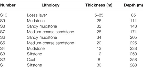
TABLE 1. Overburden composition of the working face.
The terrain of mining areas in western China is complex, and there are many gullies and valleys. The study area has large topographic relief, so it is difficult to undertake a comprehensive field survey of ground fissures. Therefore, unmanned aerial vehicle (UAV) photogrammetry is used to obtain image data in our study to analyze the morphology and distribution characteristics of ground fissures. UAV is a non-manned aircraft controlled by software program or radio remote. UAV aerial survey can quickly and efficiently obtain high-resolution remote sensing images. After batch processing, it can generate DOM (Digital Orthophoto Map), DEM (Digital Elevation Model), DLG (Digital Line Graphic), topographic map, and other thematic geographic information results. Compared with traditional satellite remote sensing and large aircraft aerial photography, UAV technology has the advantages of strong maneuverability, fast speed, and less dependence on weather and terrain (Colomina and Molina, 2014; Siebert and Teizer, 2014; Wang et al., 2022).
On 17 January 2022, a photographic survey of the study area was carried out using the Dajiang Elves 4pro UAV. The UAV carries a 1-inch 20 million-pixel image Sony Exmor R CMOS sensor that captures 4K /60fps video and takes static photos at 14 per second. Table 2 shows the main parameters of the aircraft. Before aerial photography, the route should be set according to the terrain above the working face. Figure 2 shows the route design.

TABLE 2. UAV parameters.
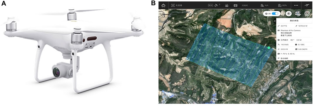
FIGURE 2. Route design. (A) UAV. (B) Route design.
In this photogrammetry, the ground resolution was 5.6 cm /pixel, and the flight height was 200 m (calculation of the flight height based on formula 1). The front overlap was 75%, and the side overlap was 60% (calculation of overlap based on formulas 2 and 3). The image size was 5472 × 3648 pixels. There is a total of 948 JPEG images. The acquired UAV image data and image control results were measured and calculated by automatic aerial triangulation encryption using Agisoft Photoscan Professional 1.4.2 software, and DSM, DOM, and 3D model were generated. The UAV operation process is shown in Figure 3:
where H is the flight height; a is the pixel size; f is the focal length of objective lens; GSD is the ground resolution of UAV images; lx and ly are the length and width of the overlapping parts, respectively; Lx and Ly are the length and width of the entire image, respectively; and Px and Py are the front overlap and side overlap, respectively.
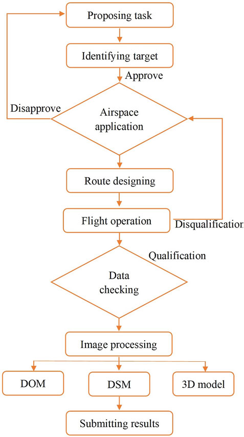
FIGURE 3. UAV operation process.
In different landform areas, the types of surface subsidence caused by coal mining are different, including ground fissures, collapses, landslides, and so on (Gao et al., 2018). The main monitoring object of this article is the ground fissures caused by coal mining. In the obtained image data, the spectral and spatial characteristics of ground objects are used to identify different ground objects. Having analyzed the shape, color, and size of mining ground fissures, the interpretation characteristics of fissures are established, as shown in Table 3.

TABLE 3. Interpretation characteristics of ground fissures.
The distribution characteristics are obtained by the visual interpretation of the generated DOM and 3D model when interpreting ground fissures. In general, the recognition accuracy of DOM is higher than the 3D model. However, when there is dense vegetation or occlusion and if fissures are difficult to distinguish from the background, ground fissures can be determined by arbitrarily rotating the 3D model. Therefore, in this study, the interpretation of ground fissures was based on the DOM, supplemented by the 3D model.
PFC (particle flow code) is a method based on discontinuous medium mechanics (discrete element). Unlike the finite element method, PFC reflects its macroscopic state through the interaction between macroscopic and microscopic mechanical properties of particles. The particle flow theory forms an arbitrary combination by connecting two or more particles. Newton’s second law and force-displacement law are used to simulate the block motion alternately. Figure 4 shows the calculation cycle process (Zhou et al., 2000).
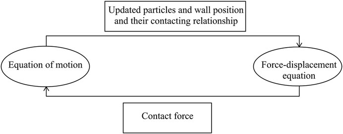
FIGURE 4. Principle of PFC.
This article adopts PFC5.0 software (two-dimensional version) developed by Itasca, the United States. The model established by PFC is composed of spherical or circular particles tightly packed by bonds, which is called BPM (bonded particle model). Therefore, unlike other methods, PFC has no grid and grid concept. Under the action of stress, the destruction of bonds leads to tensile or shear fissures between particles, so this numerical method can be applied to the field of mining subsidence to simulate the generation and development of ground fissures (Wu and Hu, 2002). The particle flow method stratified the overlying strata through the GROUP command flow. The fissures in the rock mass are simulated through the JEST command flow, and the loading of the model is simulated by moving the wall or gravity. In the process of simulation calculation, it is necessary to assume that the basic elements of the particle flow numerical model are spherical or disc-shaped. The two are rigid bodies that allow certain overlap, which is suitable for soft materials such as loess, and the rigid bodies are soft contact rather than hard contact (Itasca Consulting Group Incorporated, 2016).
1) Numerical model design
In order to eliminate the boundary effect to influence the numerical simulation results, the two-dimensional particle flow model was established with the strike profile of the working face based on the actual situation. The maximum size of the model is 864 × 288 m2. Considering the requirements of the computational efficiency and accuracy, the particle size is expanded in a certain proportion, and the particle radius is 0.4 m (Wang et al., 2017). There are a total of 229,193 particles in the proposed model. The overlying strata were divided into several layers (Table 1). In order to simulate mining, the particles of the coal seam were removed from the corresponding layers. In calculating, the horizontal displacement of the boundary on both sides of the model was constrained, and the fixed support condition was applied at the bottom. There was no constraint on the upper boundary. The gravity was 9.8 m /s2. The open-off cut distance was 243 m from the left boundary of the model, and the advance of 20 m was used to simulate the mining along the strike of the coal seam. After each excavation, it is considered to be balanced when the fissure growth rate in the numerical model is less than or equal to 5 cycles per 1000 cycles. Figure 5 shows the numerical model established by PFC2D.
2) Parameter calibration
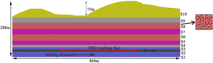
FIGURE 5. Particle flow field model.
Previously, the parallel bond contact model was often used to study the fracture failure of rock materials. However, it is found that the compression-tensile ratio of the particle aggregation is small, and the actual rock material pressure ratio is about 10. The shortage of the parallel bond model is overcome in the newly developed flat joint model (Chen, 2018). In view of this, this article adopted the flat joint model. In the flat joint model, the rigidity ratio, effective modulus, radius of particles, volume-weight, and other mesoscopic parameters were mainly included. The parameters were calibrated by continuously adjusting the mesoscopic parameters until the simulation results were as close as possible to the experimental results. Through repeated debugging, a set of mesoscopic parameters that can reflect the macroscopic mechanical properties of rock were finally obtained (Lee and Jeon, 2011). The effective modulus of the flat joint matches the macroscopic elastic modulus of the indoor test, the rigidity ratio of flat joint matches the macroscopic Poisson’s ratio of the indoor test, and the cohesion and tensile strength of the flat joint match the macroscopic cohesion and tensile strength of the indoor test. The mesoscopic parameters of the particle flow model used in this article are shown in Table 4.
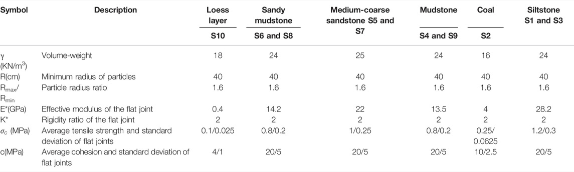
TABLE 4. Mesoscopic parameters of strata.
The “level effect” cannot be ignored in numerical simulation. So, the calculation model considering the level effect is more suitable for engineering practice. This article considered the influence of the interface between the strata on the calculation of a numerical model. The interface between the strata was treated as the contact surface, and the layer thickness was the minimum particle radius. First, the overlying strata were divided into several layers by the group command. Second, we drew the geometric model of the layer by CAD and imported it into the numerical model of the PFC program by the geometry command. The layer was placed between the strata. Finally, the corresponding mechanical parameters were contributed to different layers by the cmat command. The selected parameters were referred to in previous studies (Wang et al., 2013; Xia et al., 2016), which were roughly 1/10 of the mechanical parameters of the strata on both sides.
Figure 6 shows the interpretation result of ground fissures of 8092 working face. There are 77 ground fissures determined by visual interpretation, mainly distributed near the stopping line and the trough of the working face. Most fissures were developed in the inclined trough. The spacing was 3–18 m, and the length was 6–109 m. As for the parallel stopping line fractures, the spacing was 3–13 m, and the length was 7–138 m. The outermost ground fractures in the moving basin were 78.2 m and 55 m away from the stopping line and the trough of the working face, respectively.
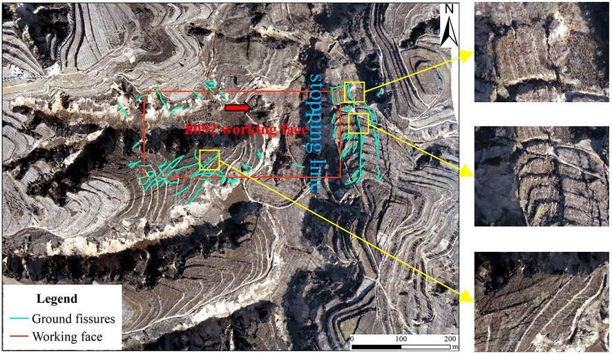
FIGURE 6. Visual interpretation of ground fissures acquired by UAV.
The plane forms of ground fissures were mainly linear and arc types. The linear fissures were straight in shape without bending and were mainly distributed along the boundary of the working face; the arc-shaped fissures were developed with a curved shape and widely distributed without distinct rules, as shown in Figure 6.
The position relationship of adjacent fissures was mainly parallel type and bifurcation type. If the development shape and angle of two or more fissures were basically the same and the relative position was parallel, their position relationship was a parallel relationship. Most of them were vertical to the advancing direction of the working face. The bifurcation fissures referred to the secondary fissures that extended from both sides of the main fissure to different directions when the main fissure developed to a certain length. They mainly were distributed outside the stopping line of the working face. The main fissure was vertical to the advancing direction of the working face, and the secondary fissure was consistent with the advancing direction of the working face, as shown in Figure 6.
The types of ground fissures were mainly tensile fissures and step fissures. Affected by the loess hilly landform, the main type of ground fissures outside the stopping line of the working face was step fissures, as shown in Figure 7–A. The maximum drop was 2.3 m. The tensile fissures were mainly distributed near the groove of the working face with flat terrain, and the maximum tensile width was 1.3 m, as shown in Figure 7–B.
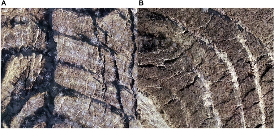
FIGURE 7. (A) Step ground fissures. (B) Tensile ground fissures.
The UAV photogrammetry time is 20 months apart from the end time of the mining face. Therefore, the surface movement and deformation have stabilized. The ground fissure obtained by visual interpretation is permanent. The main characteristics of this fissure are large width and length and the step ground fissures with a large drop.
It can be seen from the orthophoto map that the number of ground fissures above the working face is few, and the width is less, which are dynamic fissures. As the working face advanced, these fissures experienced a “generation–expansion–closure (complete or partial closure)” dynamic process. The development process of dynamic fissures is accompanied by first stretching and then squeezing the surface above the goaf.
There is different movement and deformation of the upper strata under the influence of mining during the mining stage of the working face, which can be transmitted to the surface to form ground fissures, as shown in Figure 8 (the blue lines represent the fissures, and the white lines represent the local amplification phenomena of the model).
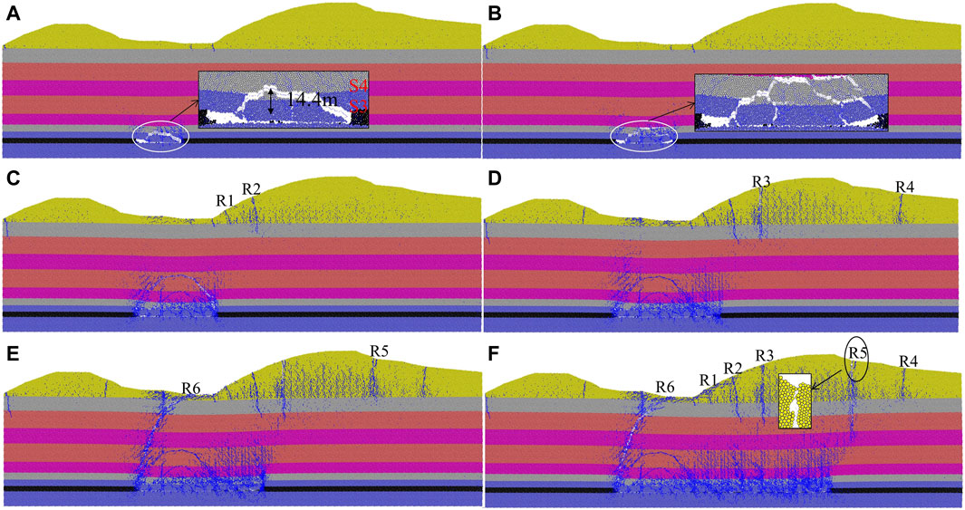
FIGURE 8. Evolution of the overlying strata at different advancing distances. (A) Advanced to 80m. (B) Advanced to 100m. (C) Advanced to 140m. (D) Advanced to 180m. (E) Advanced to 220m. (F) Advanced to 440m.
When the working face advanced to 80 m, the immediate roof collapsed for the first time, and the collapsed height was 14.4 m. At this time, the tensile stress failure in the subsidence area caused the leading edge of the slope to split. As the working face continued advancing, the direct roof fell with the mining, and the goaf area increased gradually. When the working face advanced to 100 m, the direct roof collapsed periodically, and the periodic collapse step distance was 20 m.
When the working face advanced to 140 m (slope bottom), the overburden rock blocks were continuously crushed and filled into the goaf due to the load effect of the loess layer. The failure range of the overburden rock was arched and developed upward. At this time, the slope surface pulled by the front soil caused tensile fissures R1 and R2. When the working face advanced to 180 m, the immediate roof completely collapsed to the coal seam floor, and the fissures R1 and R2 continued to develop. The moving deformation developed along the slope and then formed the fissure R3. Due to the increase of tensile stress on the upper part of the slope, there is an obvious tensile fissure R4 on the back edge of the slope due to the traction of the middle and lower soil.
When the working face advanced to 220 m, the fissure R5 appeared on top of the slope due to slope traction. The rock in the middle of the caving zone was compacted. Moreover, the fissures at the bottom of the slope were connected with the working face, forming a through mining fissure R6. At the end of the mining face, the fissures on top of the slope extended downward, and the slope became unstable with a downward sliding trend. There is a positive step failure appearing on the surface.
According to the simulation results, in the mining stage of the working face, the moving deformation at the bottom of the slope affected by mining developed from bottom to top along the slope. After the mining of the working face, a total of six obvious fissures were generated on the surface. The fissures mainly existed at the bottom of the slope, the slope surface, and the top of the slope. The fissures were positive fissures. The maximum width of the top fissure (R5) was 1.17 m. The bottom fissure was connected with the working face, and three obvious fissures were generated on the slope surface.
Coal seam excavation will cause the displacement, deformation, and failure of the overlying strata. Figure 9 shows the vertical displacement field and horizontal displacement field of overlying strata when the first caving of the direct roof and at the end of the mining face.
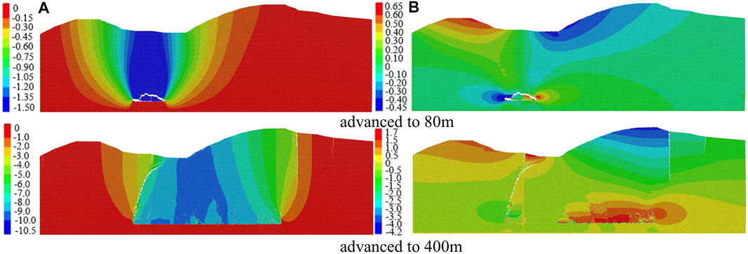
FIGURE 9. Horizontal and vertical displacement caused by mining. (A) Vertical displacement(m). (B) Horizontal displacement(m).
When the working face advanced to 80 m, the immediate roof fell for the first time, and the overlying strata around the goaf moved toward the direction of the goaf under the action of horizontal stress and self-weight. The separation occurred above the goaf. Due to the small excavation space, the surface loess layer was less affected by mining, and the subsidence of coating rock gradually decreased from bottom to top. As the working face advanced, the rock filled the goaf continuously, and the slope affected by slip was biased toward the free surface. It can be seen that the trend of the horizontal moving direction of the goaf was opposite to the slope. The fissure zone developed to the surface and formed mining fissures.
We drew the displacement curve according to the displacement data of monitoring points at different locations on the surface. Figure 10 shows the surface subsidence curve during working face mining. The subsidence curve was relatively gentle at the early stage of working face mining. The bottom of the slope was first affected by mining, and there is larger subsidence. Moreover, the slope was less affected by mining. With the expansion of the mining scope of the working face, the subsidence and the influence range on the surface gradually increased. Under the influence of the slope slip, the maximum subsidence point tended to the upward slope direction, and the subsidence curve showed a “V” shape that was not centered on the goaf. The overall trend showed that the edge of the basin was slight, while the center of the basin was larger. After working face mining, the maximum surface subsidence was 9020 mm.
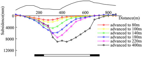
FIGURE 10. Surface subsidence curve.
Figure 11 shows the surface horizontal movement curve in the process of mining. In the early stage of working face mining, the horizontal movement curve was relatively flat, and there were two extreme values in opposite directions. With the continuous advancement of the working face, the amount of horizontal surface movement and the range of surface influence gradually increased, and the extreme value in the downhill direction moved to the edge of the basin. When the working face advanced to the bottom of the slope, the influence of slope slip was intensified. The surface horizontal movement value and influence range in the downhill direction were large, while the surface horizontal movement value and influence range in the uphill direction were small. Moreover, due to the fissures on the slope surface, there is a mutation of the horizontal movement value of the corresponding monitoring points on the surface. The maximum horizontal displacement of the surface was 4170 mm at the end of mining.
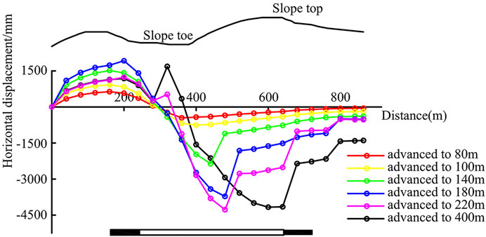
FIGURE 11. Surface horizontal displacement curve.
As Figure 11 shows, in the mining stage of the working face, the surface horizontal movement curve shows a non-asymmetric state to the zero-value point. For the point where the subsidence value in the downhill direction is zero, the horizontal movement value is not zero, and there is a large horizontal movement value. It indicates that the surface can be affected by mining and topography when the slope is mining down. The moving vector on the surface is the combination of the moving vector pointing to the goaf and the vector pointing to the downhill direction along the slope surface. The surface horizontal movement has a horizontal slip pointing in the downhill direction.
According to the surface rock movement data, after the mining of 8092 working face, the measured maximum surface subsidence value is 8920 mm, and the maximum horizontal displacement value is 3800 mm. The maximum surface subsidence value of the numerical simulation results is 9020 mm, and the maximum horizontal displacement value is 4170 mm. It can be concluded that the numerical simulation results are close to the actual results, as shown in Table 5. It shows that the results simulated by PFC numerical simulation software are reliable and correct for studying surface movement and deformation caused by underground coal mining.
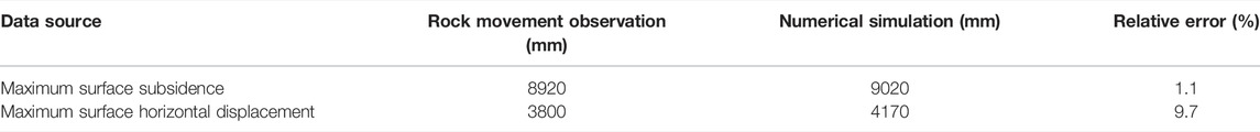
TABLE 5. Comparison of numerical simulation results and rock movement observation.
In the process of working face advancing, the overlying strata gradually collapsed to the goaf and caused the stress distribution of stope. The change of stope stress directly reflects the dynamic evolution of the overlying strata structure and the root cause of the ground fissures. Figure 12 shows the relationship between the abutment pressure of the stope in the particle flow model and the different mining distances of the coal seam. The measurement circle is arranged from the left boundary of the model on the coal seam floor. The radius is 4.2 m, and the total amount is 102.
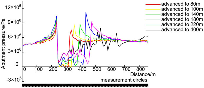
FIGURE 12. Distribution of the abutment pressure at different advancing distances.
In the process of advancing the working face, the area of increased tensile stress was just above the goaf, and the area of increased supporting pressure was in the coal wall. The values of maximum supporting pressure in the coal wall gradually increased, and the position of the maximum supporting pressure in front of the goaf continuously transferred deeper. When the working face advanced to 80 m, the immediate roof fell for the first time. The peak abutment pressure of all the measuring circles was 9.40 MPa. There is a tensile failure at the front edge of the slope under tensile stress. When the working face advanced to 100 m, the immediate roof periodically collapsed. The maximum abutment pressure of all monitoring points was 10.39 MPa. The rate of peak increase of abutment pressure was small in front of the goaf. It was directly related to the load ability of the immediate roof when transmitting grazing rock. At this time, there was no obvious deformation or failure on the slope. The change of abutment stress above the goaf was relatively complex compared with the stress change in the coal body. When the working face advanced to 180 m (just below the slope), the value of the abutment pressure at the monitoring point reached a peak, which was 11.22 MPa. This is because the direct roof fell completely, and the instability of the bearing structure of the direct roof led to the loss of the load ability to transfer. Moreover, due to the increased tensile stress of the slope surface, the fissure on the slope continued to develop, and new fissures appeared at the trailing edge of the slope under the traction. When the working face advanced to 220 m, the overlying strata on the immediate roof was totally cut down, and the overlying strata fissure was connected with the slope bottom fissure. At this time, the peak value of abutment pressure dropped sharply. After the mining of the working face, there was a step failure at the back edge of the slope, and the abutment pressure in the coal body rebounded. The maximum abutment pressure of all monitoring points was 8.57 MPa. As Figure 12 shows, the stability of the overlying strata has a significant impact on the change of abutment pressure above the goaf.
In the field investigation, the dynamic real-time differential observation (RTK) of the Zhonghaida V30 receiver was used to determine the location and shape of ground fissures, and the width and fall of ground fissures were measured by a tape ruler. The survey results are shown in Figure 13.
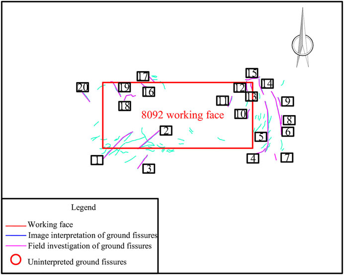
FIGURE 13. Ground fissure survey map.
We investigated 20 ground fissures randomly along the boundary of the working face and above the working face, which were tensile fissures and step fissures. The survey information is shown in Table 6.
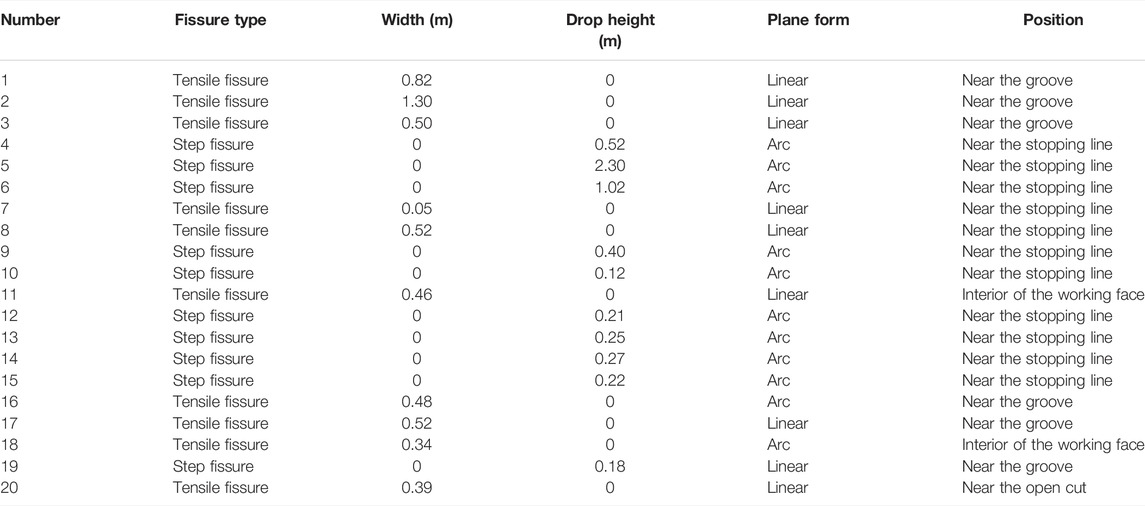
TABLE 6. Survey of ground fissures.
Comparing the field survey results with the interpretation results of UAV data, it can be seen that the fissures obtained by the field survey failed to fully reflect their plane form, and the ground fissures interpreted by UAV remote sensing technology can well reflect the tortuous shape of fissures. The ground fissure 7 cannot be accurately identified in the orthophoto. The width of the fissure is 5 cm, but the ground resolution of the UAV image is 5.6 cm /pixel. Thus, it is difficult to find ground fissure 7 through visual interpretation.
In this study, the accuracy rate of ground fissures by visual interpretation based on using UAV image data reached 95%, which verified the feasibility and applicability of UAV remote sensing technology in the investigation of ground fissures. Moreover, the use of UAV technology can save much manpower and has the characteristics of high efficiency and comprehensiveness.
According to the numerical simulation results, we analyzed the fissure development law, displacement distribution law, and abutment pressure variation law above the goaf in the mining stage of the working face. It is concluded that the surface movement and deformation of the mining under the loess gully area have different stages, and the deformation process can be divided into the following stages (Zhang et al., 2022):
1) Tensile failure of the slope bottom: in the early stage of working face mining, due to the self-gravity subsidence of the overlying strata in the goaf, the surface loess layer is bent and deformed, and the slope moves to the inner side of the goaf. The bottom of the slope is first cracked by the tensile stress of the rock and soil in the goaf, as shown in Figure 14–A.
2) Traction failure of the slope body: when the working face advances below the slope, the maximum subsidence value of the surface is in the center of the goaf. The subsidence degree of the slope bottom is deeper, and the fissures continue to extend due to the increase of tensile stress. The mining effect extends from the bottom of the slope to the slope, and the slope is pulled by the front rock and soil and then causes tensile fissures. The failure mode is traction failure, as shown in Figure 14–B.
3) Sliding failure of the slope top: as the working face advances, the range of the mined-out area increases. The upper slope moves towards the free face under the traction of the lower slope, and there are tensile fissures on the slope top. At the same time, the soil at the bottom of the slope moves toward the slope under the action of the mined-out area. The bottom of the slope is subjected to two-way extrusion, which intensifies the fissure damage. After the end of work face mining, the bottom of the slope fissures and goaf is connected to form a penetrating fissure. The slope surface and the top of the slope fissures continue to extend, and the slope loses its stability, showing a downward sliding trend, such as Figure 14–C.
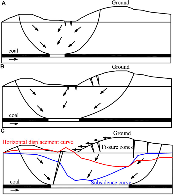
FIGURE 14. Surface movement and deformation process in the loess gully area. (A) Tensile failure of the slope bottom. (B) Traction failure of the slope body. (C) Sliding failure of the slope top.
Based on the numerical simulation results, it can be seen that the instability of the overlying strata causes the ground fissures. When the lower part of the key strata is broken and the upper part not, there will be rock fissures developed from the top to the bottom on the surface. The ground fissures characterized as tensile ground fissures constantly develop with the advancement of the working face. When the working face advances to a certain distance, the upper and lower parts of the key strata break simultaneously. The sliding instability of the key strata will cause the surface subsidence and horizontal deformation severe. At this time, the fissures above the goaf are connected with the ground fissures, which are shown as step fissures, as shown in Figure 15. If the ground fissure is in the compression deformation area of a moving basin on the surface, the width of the fissure will decrease, showing a closed trend with the surface compression deformation, that is, dynamic fissures.
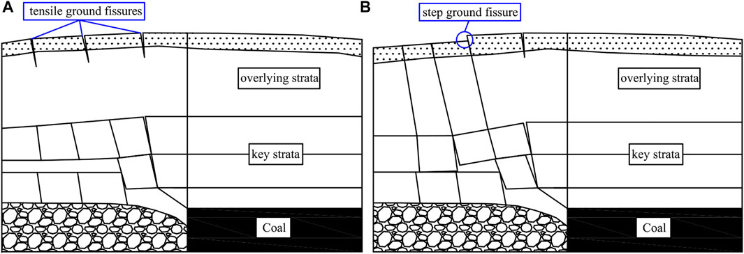
FIGURE 15. (A) Formation process of tensile ground fissures. (B) Formation process of step ground fissures.
The highlights of this study:
1) Through UAV aerial photography and field investigation, the distribution position, plane forms, location relationship, and type of ground fissures in the loess gully region are obtained, and the accuracy rate of ground fissures by visual interpretation is verified. At the same time, we get that the relationship between image pixels and the interpretation object size should be considered in the interpretation of ground disasters by UAV. The research results can provide a useful reference for rapidly monitoring large-scale geological disasters.
2) We first obtained three stages of surface movement and deformation caused by coal mining in the loess gully area. The stability of the overlying strata is reflected by analyzing the change of abutment pressure in the stope. It is concluded that the upper and lower parts of the key strata were broken at the same time and are the root cause of tensile ground fissures and step ground fissures, and the characteristics of surface movement and deformation under this geological condition are also obtained. For the first time, we consider the influence of the “level effect” on surface movement and deformation caused by coal mining in the loess gully area, which makes the simulation results more consistent with the actual. The research results provide a reference for evaluating surface movement and deformation.
Ground fissures are one of the main disasters caused by underground coal mining. It is urgent to develop a large-scale monitoring technology for ground fissures and study its development law through new methods. In this article, taking 8092 working face as an example, we studied the distribution characteristics and development law of mining ground fissures in the loess gully area by using the method of UAV photogrammetry, field investigation, and particle flow theory. We can get the following conclusions:
1) Based on the interpretation results of UAV remote sensing images, it can be seen that the mining ground fissures are mainly distributed near the stopping line and the trough of the working face under the condition of the loess gully area. Most of them were inclined trough fissures, with a fissure spacing of 3–18 m and a length of 6–109 m. The parallel stopping line fissure spacing was 3–13 m, and the length was 7–138 m. The outermost ground fissures in the moving basin were 78.2 m and 55 m away from the stopping line and the trough of the working face, respectively. The main plane form of the ground fissure was linear and arc in type. The linear fissures were more distributed along the boundary of the working face, and the arc fissures were distributed widely and randomly. There were mainly parallel type and bifurcation type for the position relationship of adjacent fissures. In terms of the types of ground fissures, there were mainly tensile fissures and bench fissures. The outside of the stopping line of the working face affected by the loess hilly landform was mainly bench fissures, and the maximum drop was 2.3 m. The tensile fissures were mainly distributed near the groove of the flat working face, and the maximum tensile width was 1.3 m. Combined with field investigation, it was found that the accuracy of visual interpretation of ground fissure by UAV image data was 95%, which verified the feasibility and applicability of UAV remote sensing technology in ground fissure investigation.
2) In the stage of coal seam mining, the failure range of the surrounding overburden rock in the goaf developed arch upward. The bottom of the slope first affected by mining caused fissures. Then, the movement deformation developed from bottom to top along the slope, and there were fissures appearing on the surface and top of the slope. The stability of the overlying strata has a significant influence on the abutment pressure change above the goaf. The upper and lower parts of the key strata breaking simultaneously are the root cause of tensile ground fissures and step fissures.
3) When mining in the loess gully area, the surface subsidence curve showed a “V” shape that was not centered on the goaf. The surface horizontal movement curve showed a non-antisymmetric state about the zero point. Since there was a horizontal slip pointing to the downhill direction in the horizontal movement of the surface, the subsidence value in the downhill direction was zero. However, the horizontal movement value was not zero, and there was a large horizontal movement value.
4) When mining in the loess gully area, the surface movement and deformation had different stages. The surface had experienced the process of tensile failure of the slope bottom—traction failure of the slope body—sliding failure of the slope top. The biggest advantage of particle flow theory is that it can directly reflect the evolution process of rock strata movement and deformation. It is more suitable for studying mining subsidence problems than other methods.
In this article, the particle flow theory is mainly used to study the formation mechanism of ground fissures in the loess gully area. It does not focus on the quantitative study of ground fissures. For the numerical model established along the strike profile of the working face, the simulation results can correctly restore the formation process of ground fissures and explain the root causes of different types of ground fissures. At the same time, the numerical model constructed by PFC is composed of many particles, and the amount of calculation is large. Therefore, in order to save computation time, the 2D version of PFC is used in this study. Future research focuses on the law and prediction of ground fissures by the 3D version of PFC.
Unfortunately, the ground resolution of the UAV used in this study is 5.6 cm /pixel, so it is impossible to interpret smaller ground fissures. In addition, the special geological structure was not considered in the numerical model based on PFC2D. Thus, there is still a little difference between the simulation results and the actual values. These limitations will be further studied in the future.
The raw data supporting the conclusion of this article will be made available by the authors without undue reservation.
Conceptualization, YZ; methodology, JK; software, YZ; validation, SL and YZ (Yuanhao Zhu); formal analysis, YZ; investigation, WZ; resources, YZ (Yuanhao Zhu); data curation, TW; writing—original draft preparation, YZ; writing—review and editing, YZ; visualization, JK; supervision, SL; project administration, YZ; funding acquisition, YZ. All authors have read and agreed to the published version of the manuscript.
This study was supported by the Shanxi Graduate Education Innovation Project of China grant number (2019SY126). The authors thank all the reviewers for their valuable comments.
The authors declare that the research was conducted in the absence of any commercial or financial relationships that could be construed as a potential conflict of interest.
All claims expressed in this article are solely those of the authors and do not necessarily represent those of their affiliated organizations, or those of the publisher, the editors, and the reviewers. Any product that may be evaluated in this article, or claim that may be made by its manufacturer, is not guaranteed or endorsed by the publisher.
Chen, P. Y. (2018). Research Progress on Pfc2d Simulation of Crack Propagation Characteristics of Cracked Rock. J. Eng. Geol. 26, 253–264. doi:10.13544/j.cnki.jeg.2017-039
Colomina, I., and Molina, P. (2014). Unmanned Aerial Systems for Photogrammetry and Remote Sensing: A Review. ISPRS J. Photogrammetry Remote Sens. 92, 79–97. doi:10.1016/j.isprsjprs.2014.02.013
Gao, G. J., Hou, E. K., Xie, X. S., Xu, Y. N., Wei, Q. M., and Liu, J. B. (2018). The Monitoring of Ground Surface Subsidence Related to Coal Seams Mining in Yangchangwan Coal Mine by Means of Unmanned Aerial Vehicle with Quad-Rotors. Geol. Bull. China 37, 2264–2269. doi:10.12097/j.issn.1671-2552.2018.12.018
Hejmanowski, R., and Malinowska, A. (2016). The Impact of Deep Underground Coal Mining on Earth Fissure Occurrence. Acta Geodyn. Geomaterialia 13, 321–330. doi:10.13168/agg.2016.0014
Huang, Q. X., Du, J. W., Hou, E. K., and Yang, F. (2019). Research on Overburden and Ground Surface Cracks Distribution and Formation Mechanism in Shallow Coal Seams Group Mining. J. Min. Saf. Eng. 36, 7–15. doi:10.13545/j.cnki.jmse.2019.01.002
Itasca Consulting Group Incorporated (2016). PFC (Particle Flow Code in 2 and 3 Dimensions); Version 5.0 [User’s Manual]. Minneapolis, MN, USA: Itasca Consulting Group Incorporated.
Lee, H., and Jeon, S. (2011). An Experimental and Numerical Study of Fracture Coalescence in Pre-cracked Specimens under Uniaxial Compression. Int. J. Solids Struct. 48, 979–999. doi:10.1016/j.ijsolstr.2010.12.001
Li, L., Wu, K., Hu, Z., Xu, Y., and Zhou, D. (2017). Analysis of Developmental Features and Causes of the Ground Cracks Induced by Oversized Working Face Mining in an Aeolian Sand Area. Environ. Earth Sci. 76, 135. doi:10.1007/s12665-017-6452-9
Li, Z. (2007). Intelligent Processing of Remote Sensing Images. Beijing: Publishing House of Electronics Industry.
Lian, X., Zhang, Y., Yuan, H., Wang, C., Guo, J., and Liu, J. (2020a). Law of Movement of Discontinuous Deformation of Strata and Ground with a Thick Loess Layer and Thin Bedrock in Long Wall Mining. Appl. Sci. 10, 2874. doi:10.3390/app10082874
Lian, X., Hu, H., Li, T., and Hu, D. (2020b). Main Geological and Mining Factors Affecting Ground Cracks Induced by Underground Coal Mining in Shanxi Province, China. Int. J. Coal Sci. Technol. 7, 362–370. doi:10.1007/s40789-020-00308-1
Lian, X.-g., Li, Z.-j., Yuan, H.-y., Liu, J.-b., Zhang, Y.-j., Liu, X.-y., et al. (2020c). Rapid Identification of Landslide, Collapse and Crack Based on Low-Altitude Remote Sensing Image of UAV. J. Mt. Sci. 17, 2915–2928. doi:10.1007/s11629-020-6080-9
Liu, H., He, C. G., Deng, K. Z., Bian, Z. F., Fan, H. D., Lei, S. G., et al. (2013). Analysis of Forming Mechanism of Collapsing Ground Fissure Caused by Mining. J. Min. Saf. Eng. 30, 380–384. doi:10.13544/j.cnki:sun:ksyl.0.2013-03-013
Peng, J., Qiao, J., Leng, Y., Wang, F., and Xue, S. (2016). Distribution and Mechanism of the Ground Fissures in Wei River Basin, the Origin of the Silk Road, the Origin of the Silk Road. Environ. Earth Sci. 75, 718. doi:10.1007/s12665-016-5527-3
Shi, W. B., Huang, R. Q., Zhao, J. J., Ju, N. P., and Xiang, X. Q. (2016). Genetic Mechanism of Mining Cracks of Gently Inclined Slope in Mountains. J. Eng. Geol. 24, 768–774. doi:10.13544/j.cnki.jeg.2016/05.006
Siebert, S., and Teizer, J. (2014). Mobile 3D Mapping for Surveying Earthwork Projects Using an Unmanned Aerial Vehicle (UAV) System. Automation Constr. 41, 1–14. doi:10.1016/j.autcon.2014.01.004
Wang, P. T., Yang, T. H., Yu, Q. L., Liu, H. L., and Zhang, P. H. (2013). On Obtaining Jointed Rock Slope Geo-Parameters and the Application of PFC2D. J. Min. Saf. Eng. 30, 560–565. doi:10.1016/j.cnki:sun:ksyl.0.2013-03-013
Wang, G., Wu, M., Wang, R., Xu, H., and Song, X. (2017). Height of the Mining-Induced Fractured Zone above a Coal Face. Eng. Geol. 216, 140–152. doi:10.1016/j.enggeo.2016.11.024
Wang, C., Zhang, C., Zhao, X., Liao, L., and Zhang, S. (2018). Dynamic Structural Evolution of Overlying Strata during Shallow Coal Seam Longwall Mining. Int. J. Rock Mech. Min. Sci. 103, 20–32. doi:10.1016/j.ijrmms.2018.01.014
Wang, R., Wu, K., He, Q., He, Y., Gu, Y., and Wu, S. (2022). A Novel Method of Monitoring Surface Subsidence Law Based on Probability Integral Model Combined with Active and Passive Remote Sensing Data. Remote Sens. 14, 299. doi:10.3390/rs14020299
Wu, Q. S., and Hu, M. B. (2002). Research Progress on Dynamic Model and Experiment of Particle Flow. Rock Soil Mech. 32, 250–258. doi:10.6052/1000-0992-2002-2-J2001-005
Xia, L., Zeng, Y. W., and Zhang, S. (2016). Influence of Meso-Mechanical Parameters of Bedding Plane on Strength Characteristics of Layered Rock Mass. J. Yangtze River Sci. Res. Inst. 33, 68–75. doi:10.11988/ckyyb.20150451
Yang, K., Hu, Z., Liang, Y., Fu, Y., Yuan, D., Guo, J., et al. (2022). Automated Extraction of Ground Fissures Due to Coal Mining Subsidence Based on UAV Photogrammetry. Remote Sens. 14, 1071. doi:10.3390/rs14051071
Yu, Q., and Guo, W. (2016). Study on Influence Scope of Underground Subcritical Extraction to Civil Buildings on Surface Ground. Coal Sci. Technol. 44, 191–195. doi:10.13199/j.cnki.cst.2016.07.033
Zhang, J., and Wang, J. (2014). Similar Simulation and Practical Research on the Mining Overburden Roof Strata “Three-zones” Height. J. Min. Saf. Eng. 31, 249–254. doi:10.13545/j.issn1673-3363.2014.02.014
Zhang, Y. X., Lan, P. T., Jin, Y. C., Zhou, L., and Cui, Y. Y. (2017). Practice and Exploration of Unmanned Aerial Vehicle Three-Dimensional Oblique Photogrammetry Technology in the Monitoring of Open Pit Mines. Bull. Surv. Mapp. S1, 114–116. doi:10.13474/j.cnki.11-2246.2017.0630
Zhang, X. H., Zhu, L., Wang, W., Li, X. J., and Ren, Y. C. (2019). Study and Application of Sequential Extraction Method of Ground Fissures Based on Object. Remote Sens. Land Resour. 31, 87–94. doi:10.6046/gtzyyg.2019.01.12
Zhang, J., Yang, M., Zhang, F., Tang, Y., Wang, X., and Wang, Y. (2020). Revealing Soil Erosion Characteristics Using Deposited Sediment Sources in a Complex Small Catchment in the Wind-Water Erosion Crisscross Region of the Chinese Loess Plateau. Geoderma 379, 114634. doi:10.1016/j.geoderma.2020.114634
Zhang, Y., Yan, Y., Dai, H., Zhu, Y., and Wu, T. (2021). Stability and Force Chain Characteristics of “Inclined Step Cutting Body” in Stope. Appl. Sci. 11, 10276. doi:10.3390/app112110276
Zhang, Y. J., Kong, J. Y., Zhu, Y. H., Zhu, W. X., He, F. S., and Wang, L. F. (2022). Influence of Underground Mining Direction Based on ParticleFlow on Deformation and Failure of Loess Gully Area. Comput. Intell. Neurosci. 2022, 1698220. doi:10.1155/2022/1698220
Keywords: UAV, particle flow theory, ground fissures, identification method, numerical simulation
Citation: Zhang Y, Kong J, Long S, Zhu Y, Zhu W and Wu T (2022) Study on the Ground Fissure Development Law of Coal Mining Based on UAV Photogrammetry and the Particle Flow Theory. Front. Environ. Sci. 10:915645. doi: 10.3389/fenvs.2022.915645
Received: 08 April 2022; Accepted: 09 June 2022;
Published: 12 July 2022.
Edited by:
Juergen Pilz, University of Klagenfurt, AustriaReviewed by:
Yunliang Tan, Shandong University of Science and Technology, ChinaCopyright © 2022 Zhang, Kong, Long, Zhu, Zhu and Wu. This is an open-access article distributed under the terms of the Creative Commons Attribution License (CC BY). The use, distribution or reproduction in other forums is permitted, provided the original author(s) and the copyright owner(s) are credited and that the original publication in this journal is cited, in accordance with accepted academic practice. No use, distribution or reproduction is permitted which does not comply with these terms.
*Correspondence: Yanjun Zhang, YnF0MjEwMDIwNDA0OUBzdHVkZW50LmN1bXRiLmVkdS5jbg==
Disclaimer: All claims expressed in this article are solely those of the authors and do not necessarily represent those of their affiliated organizations, or those of the publisher, the editors and the reviewers. Any product that may be evaluated in this article or claim that may be made by its manufacturer is not guaranteed or endorsed by the publisher.
Research integrity at Frontiers
Learn more about the work of our research integrity team to safeguard the quality of each article we publish.