- 1Key Laboratory of Desert and Desertification, Northwest Institute of Eco-Environment and Resources, Chinese Academy of Sciences, Lanzhou, China
- 2Dunhuang Gobi and Desert Ecology and Environment Research Station, Northwest Institute of Eco-Environment and Resources, Chinese Academy of Sciences, Dunhuang, China
- 3Research Station of Gobi Desert Ecology and Environment in Dunhuang of Gansu Province, Dunhuang, China
- 4Academy of Plateau Science and Sustainability, Qinghai Normal University, Xining, China
The Lanzhou-Xinjiang High-Speed Railway runs through high-wind areas in the Gobi Desert, and disasters arising from the effects of blown sand critically endanger the safety of railway operations. To prevent sand deposition on the rail bed, double rows of sand fences composed of concrete columns and plates are installed on the windward side of the railway line. However, the aerodynamic properties and sheltering effects of these fences remain unclear. In this study, the effects of sand fences on boundary wind patterns and sand transport were investigated in the field and in a wind tunnel. The following results were obtained: 1) The wind velocity was efficiently reduced on the leeward side of the first and second rows of fences by 78% and 87%, respectively. Nevertheless, owing to large openings in the fence, the sand-trapping efficiencies of the first and second rows of fences on the leeward sides were only 72 and 63%, respectively. 2) The effective shelter distance (Ds) of the fence is 10 times the height of the fence; however, the horizontal distance between the two rows of fences is much larger than the Ds of the fence. This allows the wind velocity between the fences to rise above the saltation threshold once again, thereby reducing the overall sheltering effects of the double-row of fences. This study will produce a theoretical reference for improving the design and installation of blown-sand control systems in the strong-wind regions of the Gobi.
1 Introduction
The Lanzhou-Xinjiang High-Speed Railway is the first high-speed railway in China that runs through the high-wind areas of the Gobi, including the “Yandun,” “Hundred Miles,” “Thirty Miles,” and “Dabancheng” windy areas, from east to west in Xinjiang. These areas have land surfaces characteristic of Gobi, where sand is commonly driven by strong winds, providing high kinetic energy to the transported sand particles (Tan et al., 2021; Jiang et al., 2010). The wind-blown sand seriously threatens the railway by, for example, deeply burying its tracks (Figure 1A), while the high-energy saltating particles damage road and traffic equipment (Xiao et al., 2016). The threats from such wind-blown sand in these areas endanger the operational safety of the railway (Wang et al., 2017, 2022; Huang et al., 2019; Dun et al., 2021). To protect the tracks and road traffic equipment from damage and destruction by wind-blown sand, a mechanical system to protect against wind-blown sand was designed by the railway design department and built on the windward side of the railway (Wang et al., 2018, 2020). The most important part of this control system primarily comprises two rows of concrete pillar and plate wall sections that function as a sand fence (Figure 1B), hereafter referred to as the concrete plate-insert sand fence.
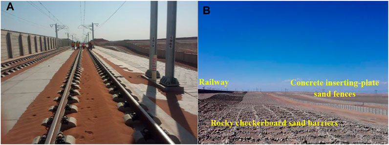
FIGURE 1. (A) Sand deposition around the rail bed; (B) blown-sand control system built on the windward side of the railway (Wang et al., 2018).
Sand fences are artificial structures used to control aeolian erosion and deposition and are one of the most important structures in aeolian engineering. Fences are constructed using materials including wood (Ling et al., 1984; Bofah and Al-Hinai, 1986), concrete (Zhang et al., 2010), nylon net (Wang et al., 2005), plastic (Zhang et al., 2021), metal (Wang et al., 2017, 2018), or vegetation (Dong et al., 2004), depending on the materials available in different areas. Common types of sand fence design-types include horizontal, upright, holed-plank, griddled, and wind-screened fences (Dong et al., 2007). The aerodynamic properties and sheltering effects of sand fences depend mainly on their geometric design and multiple design factors, including height, length, width, porosity, opening size/shape/distribution, and row numbers and the spacing between rows (Li and Sherman, 2015; Lima et al., 2020; Xin et al., 2021). The sheltering effect of multiple rows of sand fences is commonly considered to be more efficient than that of a single-row sand fence (Fang et al., 2018; Liu et al., 2018). Additionally, porosity, the ratio of a fence’s open area to its total area, is the most important structural parameter for controlling the performance of a sand fence of any given height (Heisler and Dewalle, 1988; Cornelis and Gabriels, 2005; Mustafa et al., 2016). Porosity controls not only the wind velocity reduction efficiency and effective shelter distance of the sand fence but also determines sand trapping efficiency and the location of particle deposition. Considering the combination of both the boundary wind and sediment transport effects of sand fences, their optimum porosity ranges from 30 to 50% (Perera, 1981; Grant and Nickling, 1998; Boldes et al., 2001; Cornelis and Gabriels, 2005; Dong et al., 2006) and depends upon fence material and the size, shape, and distribution of openings (Li and Sherman, 2015). At constant porosity, increases in pore diameter increases the rate of penetration of wind and sand through a sand fence and also lowers wind reduction and sand trapping efficiencies of the fence (Savage, 1963; Manohar and Bruun, 1970). Hotta et al. (1987) suggested that the opening size of a sand fence should exceed 10 times the sand diameter. In addition, early studies indicated that sand fences with sharp edges (e.g., square holes, vertical slits, or horizontal slits) have higher sand-trapping efficiencies than those with round edges (e.g., circular holes) (Richards et al., 1984). Height is another important structural parameter of sand fences and is critical for determining sand trapping efficiency and the magnitude of dune deposition (Lima et al., 2020; Ning et al., 2020; Xin et al., 2021). To trap as many transported particles as possible, fence heights usually exceed the saltation height of the wind-blown sand (Phillips and Willetts, 1979). Studies of flow fields (van Eimern et al., 1964) and sand transport regimes (Hotta and Horikawa, 1990) have shown that the shelter zone and life span of a sand fence are proportional to its height. The impact of a sand fence on local wind regime and sand transport also depends on the environmental characteristics, including incoming flow conditions (velocity, turbulence, and direction), sedimentology, and topography (Li and Sherman, 2015). The environmental characteristics of Gobi are clearly different from desert (Pi et al., 2017a; 2017b), and aeolian sediment transport over the Gobi surface exhibits extremely different characteristics than that over sand surfaces. On the Gobi surface, an elastic collision occurs between saltating particles and gravel clasts, allowing higher energy saltating particles (Tan et al., 2021) to rebound to greater heights. The bouncing height of coarse particles over Gobi surfaces under extremely strong winds can surpass 2 m (Wang et al., 2022), far greater than that over a sand surface. Therefore, the materials and geometric design of sand fences in Gobi areas differs from that in desert areas. However, there are few theoretical studies on sand fences in Gobi regions, especially in Gobi regions experiencing extremely strong winds.
The concrete plate-insert sand fence is heavy and has a capacity for high wind-resistance. Consequently, it is widely used in the high-wind areas along the Lanzhou-Xinjiang High-Speed Railway. However, the material’s properties and complex construction process result in the sand fence having a large opening size and relatively low porosity (described in subsections below). Although damage to the railway by wind-blown sand has been reduced, aeolian sand particles still accumulate around the railroad. At present, the aerodynamic properties and shelter effects of the concrete plate-insert sand fence in the Gobi regions under strong winds remain unclear. In this study, the results of wind tunnel experiments were compared with field observations to investigate the wind velocity reduction efficiency, effective shelter distance, sand-trapping efficiency, and the volume of sand deposited around the sand fence. This analysis will highlight deficiencies of fence design and produce a theoretical reference for improving the design and installation of blown-sand control systems in the strong-wind regions of the Gobi.
2 Materials and Methods
2.1 Geometric Design of the Concrete Plate-Insert Sand Fence
The height of the concrete plate-insert sand fence (CPISF) is 2 m. Each section is made of seven horizontal straight-installed plates (SIPs) (Figures 2A,B). The length, thickness, and height of the SIPs are 1.50, 0.05, and 0.25 m, respectively. There are eight rectangular holes uniformly distributed across each SIP, with each hole being 0.25 × 0.05 m in size. The porosity of the SIPs is 25%; however, as there are gaps between the SIPs after it is assembled as a fence, the overall porosity of the CPISF is increased to 30%. In each wall section, six gaps exist between the seven SIPs, with each gap being 1.50 × 0.05 m in size. The row spacing between the double-row CPISFs placed at the forefront of the wind-blown sand protection systems along the Lanzhou-Xinjiang High-Speed Railway is 74 m (equivalent to 37 H, where H is the fence height).
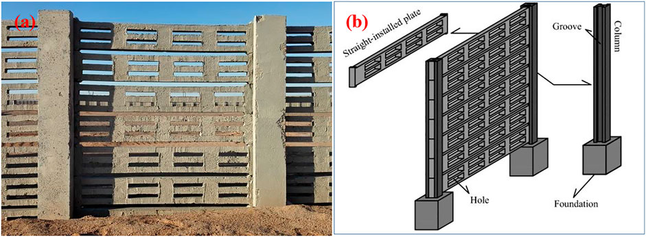
FIGURE 2. (A) Concrete plate-insert sand fence and (B) schematic diagram of the fence structure (Shi et al., 2021).
2.2 Wind Tunnel Experiments
Experiments were conducted in a wind tunnel at the State Key Laboratory of the Desertification and Aeolian Sand Disaster Combating, Gansu Desert Control Research Institute. The non-circulating blow-type wind tunnel has a total length of 38.9 m and consists of air inflow, power, stabilization, shrink, test, adjustable, and diffusion sections. The test section is 16 m long and has a cross-sectional area of 1.2 × 1.2 m. The expected wind speed in the wind tunnel ranges from 4 to 35 m s−1, and the boundary layer in the test section has a maximum thickness of 0.5 m (Wang et al., 2018).
To simulate the CPISF more realistically, we used the SIPs (Figure 3A) as the models in our wind tunnel experiments. Two groups of models were tested: 1) a single row of SIPs and 2) a double row of SIPs with a row spacing of 9.25 m (37 H). To simulate the Gobi surface, gravels sampled from the field were spread out on the floor of the tunnel test section. Free-stream wind velocities (U) of 10, 15, 20, and 25 m s−1 were selected for the measurements of wind velocity profiles in this study. The wind profiles were measured using an array of pitot-static tubes at nine heights, from 1 to 40 cm, above the wind tunnel floor; the pitot-static tubes array was moved throughout the profile along the direction of inflow, and 27 measurement points were selected around the sand fences (Figures 3B,C). For each point where wind velocity was measured, the duration of wind data acquisition was 30.0 s, with a data acquisition interval of 0.5 s. The wind data were time-averaged and interpolated via bilinear interpolation to reconstruct the flow field around the sand fences using Origin 9.6 drawing software. The relative wind velocity (u/u0) at each measurement point is the ratio of the wind velocity u to the reference velocity u0, which is the inlet velocity at the corresponding height. The following equation represents the wind velocity reduction efficiency (Rw) around the sand fences:
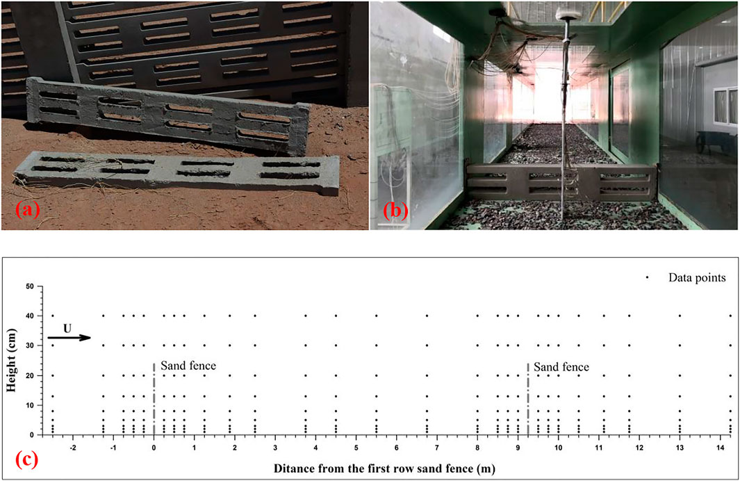
FIGURE 3. (A) Horizontally aligned straight-installed plates used in the wind tunnel; (B) wind velocity profiles measured using pitot-static tubes; and (C) the positions of wind velocity measurement points.
2.3 Field Observations
We observed the wind profiles, sand transport profiles, and shapes of the sand deposition on the windward and leeward sides of the double rows of CPISFs in the “Yandun” windy area, along the Lanzhou-Xinjiang High-Speed Railway.
The wind profiles were measured using 3-D ultrasonic anemometers (Wind Master Pro, Gill Instruments) at height, z = 1.0, 1.5, and 3.0 m above the Gobi surface. The ultrasonic anemometer array was moved throughout the profile perpendicular to the sand fences, and around the sand fences, 28 measurement points, x = −40, −30, −20, −10, −6, −4, −2, −1, 1, 2, 4, 6, 10, 20, 30, 40, 53, 63, 67, 69, 71, 72, 74, 76, 78, 80, 84, and 94 m, were selected (Figure 4A). Because of the placement requirements of the ultrasonic anemometer and the principle of velocity measurement, all ultrasonic anemometers were aligned in the direction of magnetic north. Therefore, the positive direction of the horizontal velocity (u) is due north, the positive direction of the vertical velocity (w) is vertically upwards, and the positive direction of the transverse velocity (v) is due west. For each measurement point, the duration of wind data acquisition was 5 min, with an acquisition interval of 1 s. A 3-D ultrasonic anemometer, installed at a height of 1 m, was used to establish a reference point at 60 m (30 H), windward of the first sand fence row. The wind velocity profiles around the sand fences were measured from 11:00 to 17:50 on 11 November 2016. The 10-min average wind velocity at a height of 2 m during the observation period varied from 9.32 to 12.15 m s−1, with a mean of 10.66 m s−1. The wind direction during the whole measurement period was relatively steady, and the 10-min average angles ranged from 59.33° to 76.48°, with a mean of 67.43° (ENE winds). Post-processing of data acquired from the ultrasonic anemometer conducted as described by Walker (2005). The higher acquisition frequency of 3-D ultrasonic anemometer allows the analysis of airflow turbulence, and hence, we calculated the turbulence intensity (Tu) using the following formula (Bennett and Best, 1995; Venditti and Bauer, 2005):
where ui’ is the horizontal fluctuating wind velocity, ui is the horizontal instantaneous wind velocity, and
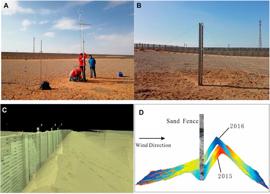
FIGURE 4. (A) 3-D ultrasonic anemometers used to measure the wind profiles around the sand fences; (B) the sand sampler located windward of the first sand fence row; (C) scanning image of the deposited sand dune, as captured by a 3-D laser scanner; and (D) DEM model of the dunes deposited, depicted in ArcGIS software.
Sand transport profiles were measured using three vertically segmented sand samplers. The height and width of the sand samplers were 2.8 m and 0.03 m, respectively, with segments at 5 cm and 10 cm intervals in the lower 1.3 m and upper 1.5 m of the samplers, respectively. The first sand sampler was located 60 m (30 H) windward of the first sand fence row (Figure 4B) and was used to measure the quantity of sand transported over the gravel surface without sand fences. The second and third sand samplers were located 20 m (10 H) leeward of the first and second rows of sand fences and were used to measure the quantity of sand transported over the gravel surface after interaction with the sand fences. All sand samplers were situated perpendicular to the prevailing wind direction. The sand transport profiles were measured from January to March 2016. During the observation period, there were six intense sandstorms, and the duration of each sandstorm exceeded 18 h (Table 1). Profiles of the rate of sand transport (Q) on the windward and leeward sides of the fences were obtained by converting the masses of sand collected at each sampling height of the sand samplers into rates (kg m−1). The sand trapping efficiency (Ts) of the sand fences can be represented by the following equation:
where Qtl and Qtw are the total rates of sand transport on the leeward and windward sides of the fences, respectively.

TABLE 1. Basic information for the six sandstorms that occurred during the observation period (January to March 2016) to collect sand transport data (the wind data was obtained from a meteorological station (Gill MaxiMet GMX600), located approximately 1 km northeast of the observation site; both wind velocity and direction were measured at a height of 2.0 m).
A 3-D laser scanner (Leica Scan Station C10; detailed information on this device is described in An et al., 2018) was used to obtain point-cloud data of the shapes of sand deposits on both sides of the sand fences (Figure 4C). Multistation scanning was performed at the surveyed sites. Sphere targets were used to join and mosaic the overlapping data from multiple stations, with four sphere targets set between every two stations, limiting alignment errors to no more than 6 mm. Cyclone software was used to splice the data from different sites and eliminate the interference from point cloud data. ArcGIS software was used to establish TIN and DEM models (Figure 4D), and accurate data for the dynamic deposition of sand were obtained. Field operations were carried out on 15 September 2015 and 14 September 2016.
3 Results
3.1 Wind Tunnel Experiments
3.1.1 Airflow Field
On the windward side of the single-row SIP fence, wind velocity decreased gradually as it approached the fence, with a deceleration zone emerging at x = −1.25–0 m (−5–0 H); the deceleration zone contained a small eddy field at x = −0.25–0 m (−1–0 H) (Figure 5). When airflow approached the fence, the blocking effect of the fence resulted in an upward vertical velocity component, and thus, an acceleration zone emerged over the top of the fence. On the leeward side of the fence, a main deceleration zone emerged below the height of the fence, located at x = 0–2.5 m (0–10 H). The main deceleration zone contained a larger eddy field at x = 0–1.25 m (0–5 H), which was 0.13 m (0.52 H) high. Behind the main deceleration zone (x = 2.5–7.5 m, i.e., 10–30 H), the upward acceleration flow reattached to the ground, and airflow velocity gradually recovered; this zone can be referred to as the restoration zone.
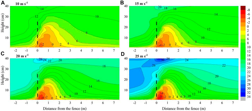
FIGURE 5. Velocity contours (m s−1) in the vicinity of the single-row straight-installed plate (SIP) under different free-stream wind velocities. The negative wind velocities represent recirculated airflow, and the dashed line shows the position of sand fences.
For double-row SIPs (Figure 6), airflow patterns around the first sand fence were similar to those around the single fence. For the second sand fence, wind velocity did not fully recover to the incoming wind velocity when it was first approaching the fence; hence, the eddy field leeward of the second fence was slightly smaller than that leeward of the first fence. In addition, under different free-stream wind velocities, the airflow patterns were similar around both the single- and double-row SIPs.
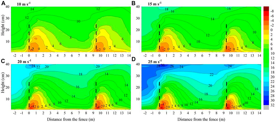
FIGURE 6. Velocity contours (m s−1) in the vicinity of the double-row straight-installed plates (SIPs) under different free-stream wind velocities. The negative wind velocities represent recirculated airflow, and the dash line shows the position of sand fences.
3.1.2 Wind Velocity Reduction and Effective Shelter Distance
Patterns in the variations in wind velocity at different heights corresponding to various distances from the fences were similar. Figure 7 illustrates relative wind velocity, u/u0, in the vicinity of the single- and double-row SIPs at a height of 13 cm (0.52 H), under different free-stream wind velocities. Variations in wind velocity at various distances from each sand fence decreased slightly on the windward side and considerably on the leeward side. The minimum velocity was close to the fence but gradually recovered as distance from the fence increased. The reduction and recovery trends were similar for different free-stream wind velocities.

FIGURE 7. Relative wind velocity versus distance for the (A) single-row straight-installed plate (SIP) and (B) double-row SIPs at a height of 13 cm (0.52 H) under different free-stream wind velocities.
For the single-row SIP (Figure 7A), the minimum u/u0 appeared at x = 1.25 m (5 H). The average u/u0 was 0.09, and the velocity recovered to 0.75 u0 at x = 7.5 m (30 H). For the double-rows SIPs (Figure 7B), the minimum u/u0 appeared at x = 1.25 m (5 H leeward of the first-row fence) and 10.50 m (5 H leeward of the second-row fence), with average u/u0 being 0.09 and 0.11, respectively. Velocity recovered to 0.75u0 at x = 8.0 m (32 H leeward of the first sand fence row) and 0.70 u0 at x = 14.25 m (20 H leeward of the second sand fence row). According to Eq. 1, the maximum Rw on the leeward side of the single-row and double-row SIPs were 91 and 89%, respectively.
The effective shelter distance (Ds) of the sand fence is the distance within which wind velocity is reduced below the threshold wind velocity (ut) (Dong et al., 2006), which, at a height of 13 cm over the artificial gravel surface, was 6.54 m s−1 in our wind tunnel experiment. The corresponding ut/u0 at a height of 13 cm under free-stream wind velocities of 10, 15, 20, and 25 m s−1 were 0.53, 0.39, 0.31, and 0.25, respectively. According to the u/u0 at a height of 13 cm in the vicinity of the single-row SIP (Figure 7A), wind velocity leeward of the fence recovered to the threshold values at x = 3.75, 2.5, 1.875, and 1.875 m (15, 10, 7.5 and 7.5 H), under free-stream wind velocities of 10, 15, 20, and 25 m s−1, respectively, with a mean of x = 2.5 m (10 H). Thus, the average Ds of the SIP was 10 H.
3.2 Field Observations
3.2.1 Variations in Airflow
Figure 8 shows variations in airflow at different heights around the CPISFs measured in the field. Patterns in the variations in wind velocity at various distances from each sand fence were similar to those tested in the wind tunnel (Figure 8A). The horizontal wind velocity (u) was on average reduced to 0.22 uref at x = 10 m (5 H leeward of the first fence), which then recovered to 0.50 uref at x = 67 m (33.5 H leeward of the first sand fence row). However, it was again reduced to 0.13 uref at x = 84 m (5 H downwind of the second sand fence row). This indicates that the maximum Rw on the leeward side of the first and second CPISF rows were 78 and 87%, respectively. The vertical wind velocity (w) accelerated considerably as the airflow approached the fence, and its upward vertical velocity increased to approximately 10 wref between the heights of 1.0 and 1.5 m and 20 wref at the height of 3.0 m at x = 1 m (0.5 H windward of the first fence) (Figure 8B). The horizontal wind direction changed to gradually become parallel to the sand fences as the wind approached the fences (on the windward sides), which indicates the occurrence of a transversal displacement flow (Figure 8C). Turbulence was greatly intensified by the fences, with an average value of 0.13 when there was no fence and increased to 0.35 and 0.52 on the leeward sides of the first and second fences, respectively (Figure 8D).
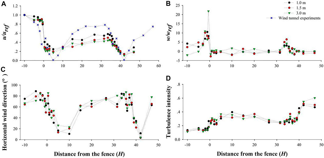
FIGURE 8. Variations in (A) horizontal wind velocity, (B) vertical wind velocity, (C) horizontal wind direction, and (D) turbulence intensity at different heights around the concrete plate-insert sand fences (CPISFs), as measured in the field.
3.2.2 Sand-Trapping Efficiency
Figure 9 shows the profiles of the rate of sand transport (Q) upwind and downwind of the CPISFs during the observation period. The profiles all obey an exponential decay function. Below the height of the sand fences, Q downwind of the sand fences was lower than that over the Gobi surface without a sand fence, whereas above the height of the sand fences, it was slightly larger than that over the Gobi surface without a sand fence. In general, Q was substantially lower downwind of sand fences. However, it was interesting that Q downwind of the first CPISF was less than that downwind of the second CPISF. According to Eq. 4, the Ts on the leeward side of the first and second CPISF were 72.43 and 62.97%, respectively.
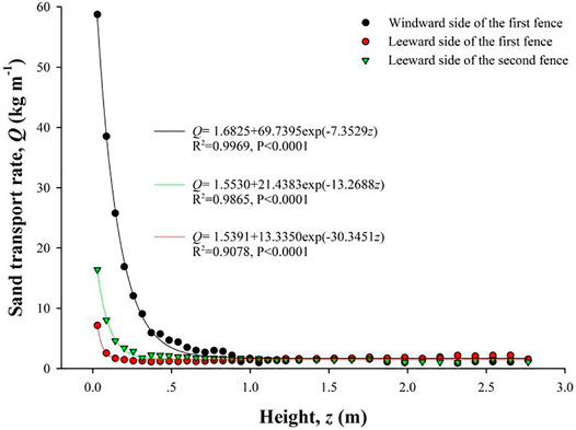
FIGURE 9. Sand transport rate profiles upwind and downwind of the concrete plate-insert sand fences (CPISFs) during the observation period.
3.2.3 Morphologies of Sand Depositions
Figure 10 shows the morphologies of the sand deposited on the windward and leeward sides of the first and second CPISF in 2015 and 2016; it was clear that dunes developed on both sides of the two fences. On the windward side of the first fence, sand deposition began at x = −8 m (−4 H), the dune crest was located at x = −2 m (−1 H), and the height of the crest was 0.7 m (0.35 H). However, on the leeward side of the first fence, sand was deposited at x = 0–7 m (0–3.5 H), the dune crest was located at x = 2 m (1 H), and the height of the crest was 1.3 m (0.65 H) in 2015, increasing to 1.5 m (0.75 H) in 2016. On windward side of the second fence, sand deposition began at x = −6 m (−3 H), the dune crest was located at x = 0.5 m (0.25 H), and the height of the crest was 0.6 m (0.3 H). On the leeward side of the second fence, sand deposition began at x = 0–7 m (0–3.5 H), the dune crest was located at x = 1.5 m (0.75 H), and the height of the crest was 1.0 m (0.5 H). From 2015 to 2016, the incremental sand deposition volumes on the windward and leeward sides of the first and second CPISFs were 0.17 and 1.00 m3 m−1 and 0.11 and 0.08 m3 m−1, respectively (Table 2).

FIGURE 10. Morphology of the deposited sand on the windward and leeward sides of the (A) first and (B) second concrete plate-insert sand fences (CPISFs) in 2015 and 2016. The red and black dashed lines show the dune shapes in 2016 and 2015, respectively.

TABLE 2. Volume of deposited sand on the windward and leeward sides of the first and second concrete plate-insert sand fences (CPISFs) in 2015 and 2016.
4 Discussion
4.1 Airflow Field and Wind Shelter Effects
The airflow field in the vicinity of a sand fence determines the sand transport and deposition regime around the fence (Li and Sherman, 2015). A deceleration zone containing a small eddy field appeared in the windward airflow around the SIPs of the sand fence, while an acceleration zone emerged over the top of the fence. Additionally, a main deceleration zone with a larger eddy field appeared leeward of the fence, and a restoration zone was present behind the main deceleration zone. This was consistent with the airflow regimes identified near sand fences in previous studies (Dyunin, 1964; Plate, 1971; Judd et al., 1996; Dong et al., 2007). In theory, transported sand is deposited in deceleration zones. Our field measurements demonstrated that sand was indeed deposited in the windward and leeward deceleration zones of the double-row CPISFs and that sand dunes developed on both sides of the fences, indicating that the fences sufficiently reduced wind velocity. Eddy fields only appeared when the porosity of the sand fence was lower than 40% (Gloyne, 1954; Lee and Kim, 1999). Eddy fields appeared on both the windward and leeward sides of the SIP, which indicates that the fence induced a strong disturbance in the airflow field and that turbulence around the fence was intensified (Lee and Lee, 2012). The field observations demonstrated that turbulence was greatly intensified by the presence of the CPISFs and increased 2.7 and 4.0 times on the leeward sides of the first and second rows of the sand fence, respectively. Owing to the intense blocking effect of the low-porosity SIP, a vertical displacement flowfield was present, which formed an acceleration zone over the top of the fence. This is consistent with field observations that the upward vertical velocity increased to approximately 20 wref over the top of the CPISF. In addition, the direction of horizontal wind gradually became parallel to the sand fences as the wind approached the CPISFs, which indicates that a transverse displacement flow also appeared windward of the fences (Huang et al., 2013).
Traditionally, the wind-shelter effects of sand fences have been evaluated based on the wind velocity reduction efficiency (Rw) and effective shelter distance (Ds). The results of 3D-CFD simulations have indicated that maximum Rw decreases with increasing fence porosity (Fang et al., 2018). Our wind tunnel experiments demonstrated a limit in the maximum Rw of individual SIPs of 91%, but when they were assembled as a CPISF in the field, their maximum Rw was reduced to 78%, owing to the higher porosity of the sand fences in the final assembly. The optimal spacing between multiple rows of sand fences is determined by the Ds of the fence (Dong et al., 2006; Liu et al., 2018). Previous studies suggested that the peak value of Ds occurs with a fence porosity of 30–40%, and the optimal spacing of double-row sand fences with 30–40% porosity is approximately 5–7 H (Boldes et al., 2001; Wu et al., 2013; Fang et al., 2018). Our wind tunnel experiments demonstrated that the Ds of the SIP decreased as free-stream wind velocities increased, with an average value of 10 H. However, the spacing between the double-row CPISFs of the system installed as protection against wind-blown sand along the Lanzhou-Xinjiang High-Speed Railway is 37 H, which is much larger than the Ds of the sand fence. Consequently, the distance between the first and second sand fence is wide enough for the wind velocity to recover to velocities above the saltation threshold velocity. The impact of the first sand fence on the second sand fence is dissipated, and the two fences function independently.
4.2 Sand-Trapping Efficiency and Dune Growth
In field observations, Ts values on the leeward side of the first and second CPISF fences were 72.43 and 62.97%, respectively. These observations raise two questions. First, why was the Ts on the leeward side of the second CPISF fence lower than that of the first? On the one hand, sand dunes developed in front of and behind the fences provided ramps for sand to blow over each fence. Furthermore, as discussed above, the spacing between the two fences is much larger than the Ds of the sand fence, allowing the wind velocity between the two fences to recover above the saltation threshold velocity. Thus, sand on the ground surface between the two fences becomes entrained by the wind and transported downwind. Because of these two effects, the rate of sand transport downwind of the second fence exceeded that downwind of the first fence. Second, why was the Rw of the CPISF high but its Ts low? Most previous studies indicate that the maximum Ts of a sand fence is obtained with a porosity of 40–50% (Manohar and Bruun, 1970; Bofah and Al-Hinai, 1986; Zhang et al., 2004), and fences that are spaced too closely will change the wind direction, causing relatively low Ts (Savage and Woodhouse, 1968). In the current study, wind velocities were adequately reduced because of the low porosities of the CPISF; however, the large size of the openings in the fences allowed more sand particles to be transported through them and reduced the Ts of the fences (Savage, 1963; Savage and Woodhouse, 1968; Manohar and Bruun, 1970; Lee and kim 1999).
Wind tunnel experiments by Hotta and Horikawa (1990) demonstrated that sand is deposited on both sides of a sand fence when its porosity exceeds 10% and that dune deposition leeward of the fence occurs more intensely than that on the windward side. In addition, sand fences with 40% porosity trap larger volumes of sand, and lower porosity sand fences are more easily buried by dunes. Our field measurements showed that dunes developed on both sides of the double-row CPISFs and that the leeward dunes were larger than the windward dunes. The leeward dunes at the first and second fences grew to 75 and 50% of the fence height in 2016, respectively, and dune deposition continued at rapid rates each year. The growth of the sand dunes around the CPISFs is expected to decrease the sand trapping efficiencies of the sand fences (Ning et al., 2020), and they may gradually lose their sand-blocking capacity once the deposited dunes grow to 80% of the height of the fence (Hotta and Horikawa, 1990).
5 Conclusion
We studied the aerodynamic properties and shelter effects of a CPISF along the Lanzhou-Xinjiang High-Speed Railway in Gobi regions under strong winds, using wind tunnel experiments and field observations. The main conclusions are as follows:
1) Deceleration zones appeared on the windward and leeward sides of the sand fence, and sand was deposited in corresponding deceleration zones. Eddy fields also appeared on the windward and leeward sides of the fence owing to the relative low fence porosity.
2) The Rw of the sand fence was high, and the maximum Rw values on the leeward side of the first and second fences were 78 and 87%, respectively. However, because of the large size of the openings in the sand fence, the Ts of the sand fence was low, that is, only 72 and 63% on the leeward side of the first and second fences, respectively.
3) The Ds of the sand fence was 10 H. However, the row spacing between the two sand fences constructed in the field is much larger than the Ds of the fence, which allows the wind velocity between the double-row sand fences to recover to velocities above the saltation threshold velocity. Thus, the overall shelter effects of the double-row sand fences were significantly diminished.
Data Availability Statement
The raw data supporting the conclusion of this article will be made available by the authors, without undue reservation.
Author Contributions
TW: conceptualization, investigation, data curation, writing–original draft preparation. JQ: supervision, project administration, funding acquisition. QN: methodology, investigation, writing–reviewing and editing. ZA: formal analysis. YG: formal analysis. HW: investigation. BN: investigation.
Funding
This work was financially supported by the National Natural Science Foundation of China (41730644 and 41901011), the Open Fund of State Key Laboratory Breeding Base of Desertification and Aeolian Sand Disaster Combating (GSDC201903), the Natural Science Foundation of Gansu Province, China (20JR10RA231), and the fellowship of China Postdoctoral Science Foundation (2021M703466).
Conflict of Interest
The authors declare that the research was conducted in the absence of any commercial or financial relationships that could be construed as a potential conflict of interest.
Publisher’s Note
All claims expressed in this article are solely those of the authors and do not necessarily represent those of their affiliated organizations or those of the publisher, the editors, and the reviewers. Any product that may be evaluated in this article, or claim that may be made by its manufacturer, is not guaranteed or endorsed by the publisher.
References
An, Z.-s., Zhang, K.-c., Tan, L.-h., Zhang, H., and Niu, B.-c. (2018). Dune Dynamics in the Southern Edge of Dunhuang Oasis and Implications for the Oasis protection. J. Mt. Sci. 15 (10), 2172–2181. doi:10.1007/s11629-017-4723-2
Bennett, S. J., and Best, J. L. (1995). Mean Flow and Turbulence Structure over Fixed, Two-Dimensional Dunes: Implications for Sediment Transport and Bedform Stability. Sedimentology 42, 491–513. doi:10.1111/j.1365-3091.1995.tb00386.x
Bofah, K. K., and Al-Hinai, K. G. (1986). Field Tests of Porous Fences in the Regime of Sand-Laden Wind. J. Wind Eng. Ind. Aerodynamics 23, 309–319. doi:10.1016/0167-6105(86)90051-6
Boldes, U., Colman, J., and Marañon Di Leo, J. (2001). Field Study of the Flow behind Single and Double Row Herbaceous Windbreaks. J. Wind Eng. Ind. Aerodynamics 89, 665–687. doi:10.1016/s0167-6105(01)00065-4
Cornelis, W. M., and Gabriels, D. (2005). Optimal Windbreak Design for Wind-Erosion Control. J. Arid Environments 61 (2), 315–332. doi:10.1016/j.jaridenv.2004.10.005
Dong, Z. B., Luo, W. Y., Qian, G. Q., and Wang, H. T. (2007). A Wind Tunnel Simulation of the Mean Velocity fields behind Upright Porous Fences. Agric. For. Meteorology 146 (1-2), 82–93. doi:10.1016/j.agrformet.2007.05.009
Dong, Z., Chen, G., He, X., Han, Z., and Wang, X. (2004). Controlling Blown Sand along the Highway Crossing the Taklimakan Desert. J. Arid Environments 57 (3), 329–344. doi:10.1016/j.jaridenv.2002.02.001
Dong, Z., Qian, G., Luo, W., and Wang, H. (2006). Threshold Velocity for Wind Erosion: the Effects of Porous Fences. Environ. Geol. 51 (3), 471–475. doi:10.1007/s00254-006-0343-9
Dun, H., Xin, G., Huang, N., Shi, G., and Zhang, J. (2021). Wind-Tunnel Studies on Sand Sedimentation Around Wind-Break Walls of Lanxin High-Speed Railway II and its Prevention. Appl. Sci. 11, 5989. doi:10.3390/app11135989
Dyunin, A. K. (1964). The Analytic Determination of the Surface Wind Velocity behind Open Snow Fences. Washington, DC: US Department of Commerce.
Fang, H., Wu, X., Zou, X., and Yang, X. (2018). An Integrated Simulation-Assessment Study for Optimizing Wind Barrier Design. Agric. For. Meteorology 263, 198–206. doi:10.1016/j.agrformet.2018.08.018
Gloyne, R. W. (1954). Some Effects of Shelterbelts upon Local and Micro Climate. Forestry 27 (2), 85–95. doi:10.1093/forestry/27.2.85
Grant, P. F., and Nickling, W. G. (1998). Direct Field Measurement of Wind Drag on Vegetation for Application to Windbreak Design and Modelling. Land Degrad. Dev. 9, 57–66. doi:10.1002/(sici)1099-145x(199801/02)9:1<57::aid-ldr288>3.0.co;2-7
Heisler, G. M., and Dewalle, D. R. (1988). 2. Effects of Windbreak Structure on Wind Flow. Agric. Ecosyst. Environ. 22-23, 41–69. doi:10.1016/0167-8809(88)90007-2
Hotta, S., and Horikawa, K. (1990). “Function of Sand Fence Placed in Front of Embankment,” in Proceedings of the 22nd Conference on Coastal Engineering, July 2–6, 1990 (Delft, Netherlands: AMCE) 1 (9), 2754–2767. doi:10.9753/icce.v22.%25p
Hotta, S., Kraus, N. C., and Horikawa, K. (1987). Function of Sand Fences in Controlling Wind-Blown Sand. Coastal Sediments 87, 772–787.
Huang, N., Gong, K., Xu, B., Zhao, J., Dun, H., He, W., et al. (2019). Investigations into the Law of Sand Particle Accumulation over Railway Subgrade with Wind-Break wall. Eur. Phys. J. E 42, 145. doi:10.1140/epje/i2019-11910-0
Huang, N., Xia, X., and Tong, D. (2013). Numerical Simulation of Wind Sand Movement in Straw Checkerboard Barriers. Eur. Phys. J. E 36, 99. doi:10.1140/epje/i2013-13099-6
Jiang, F. Q., Li, Y., Li, K. C., Cheng, J. J., Xue, C. X., and Ge, S. C. (2010). Study on Structural Characteristics of Gobi Wind Sand Flow in 100 Km Wind Area Along Lan-Xin Railway. J. China Railway Soc. 32 (3), 105–110. doi:10.3969/j.issn.1001-8360.2010.03.019
Judd, M. J., Raupach, M. R., and Finnigan, J. J. (1996). A Wind Tunnel Study of Turbulent Flow Around Single and Multiple Windbreaks, Part I: Velocity fields. Boundary-Layer Meteorology 80 (1-2), 127–165. doi:10.1007/bf00119015
Lee, J. P., and Lee, S. J. (2012). PIV Analysis on the Shelter Effect of a Bank of Real Fir Trees. J. Wind Eng. Ind. Aerodynamics 110 (11), 40–49. doi:10.1016/j.jweia.2012.07.003
Lee, S.-J., and Kim, H.-B. (1999). Laboratory Measurements of Velocity and Turbulence Field behind Porous Fences. J. Wind Eng. Ind. Aerodynamics 80 (3), 311–326. doi:10.1016/s0167-6105(98)00193-7
Li, B., and Sherman, D. J. (2015). Aerodynamics and Morphodynamics of Sand Fences: A Review. Aeolian Res. 17, 33–48. doi:10.1016/j.aeolia.2014.11.005
Lima, I. A., Parteli, E. J. R., Shao, Y., Andrade, J. S., Herrmann, H. J., and Araújo, A. D. (2020). CFD Simulation of the Wind Field over a Terrain with Sand Fences: Critical Spacing for the Wind Shear Velocity. Aeolian Res. 43, 100574. doi:10.1016/j.aeolia.2020.100574
Ling, Y. Q., Jin, J., Zou, B. G., Cong, Z. L., and Wen, X. L. (1984). Effect of Fence Techniques in Leveling Sand Accumulation Around Sand-Breaks--Case Study in Shapotou District. J. Desert Res. 4 (3), 16–25.
Liu, C., Zheng, Z., Cheng, H., and Zou, X. (2018). Airflow Around Single and Multiple Plants. Agric. For. Meteorology 252, 27–38. doi:10.1016/j.agrformet.2018.01.009
Manohar, M., and Bruun, P. (1970). Mechanics of Dune Growth by Sand Fences. Dock and Harbour Authority 51, 243–252.
Mustafa, M., Xu, Y., Haritos, G., and Kenji, K. (2016). Measurement of Wind Flow Behavior at the Leeward Side of Porous Fences Using Ultrasonic Anemometer Device. Energ. Proced. 85, 350–357. doi:10.1016/j.egypro.2015.12.261
Ning, Q., Li, B., and Ellis, J. T. (2020). Fence Height Control on Sand Trapping. Aeolian Res. 46, 100617. doi:10.1016/j.aeolia.2020.100617
Perera, M. D. A. E. S. (1981). Shelter behind Two-Dimensional Solid and Porous Fences. J. Wind Eng. Ind. Aerodynamics 8, 93–104. doi:10.1016/0167-6105(81)90010-6
Phillips, C. J., and Willetts, B. B. (1979). Predicting Sand Deposition at Porous Fences. J. Wtrwy., Port, Coast., Oc. Div. 105, 15–31. doi:10.1061/jwpcdx.0000129
Pi, H., Sharratt, B., and Lei, J. (2017b). Atmospheric Dust Events in central Asia: Relationship to Wind, Soil Type, and Land Use. J. Geophys. Res. Atmos. 122, 6652–6671. doi:10.1002/2016jd026314
Pi, H., Sharratt, B., and Lei, J. (2017a). Windblown Sediment Transport and Loss in a Desert-Oasis Ecotone in the Tarim Basin. Sci. Rep. 7, 7723. doi:10.1038/s41598-017-04971-4
Plate, E. J. (1971). The Aerodynamics of Shelter Belts. Agric. Meteorology 8, 203–222. doi:10.1016/0002-1571(71)90109-9
Richards, P. J., Kay, E. F., Russell, D., and Wilson, G. R. C. (1984). Porous Artificial Windbreaks in Oblique Winds. Hastings: Paper 67/84 for Institute of Professional Engineers of New Zealand (IPENZ) Conference 10, 1–10.
Savage, R. P. (1963). Experimental Study of Dune Building with Sand Fences. Mexcio City: Proceedings of 8th Conference on Coastal Engineering, 380–396.
Savage, R. P., and Woodhouse, W. W. (1968). “Creation and Stabilization of Coastal Barrier Dunes,” in Proceedings of 11th Conference on Coastal Engineering, September, 1968 (London, United Kingdom: US Coastal Engineering Research Center) 1 (11), 617–685. doi:10.9753/icce.v11.43
Shi, L., Wang, D., Cui, K., and Xue, C. (2021). Comparative Evaluation of concrete Sand-Control Fences Used for Railway protection in strong Wind Areas. Rail. Eng. Sci. 29 (2), 183–198. doi:10.1007/s40534-020-00228-5
Tan, L. H., Qu, J. J., Wang, T., Zhang, K., and An, Z. S. (2021). Field Observation Evidence for Kink Points in the Vertical Kinetic Energy Flux Profiles of Wind-Blown Sand over Gobi and its Significance. Geophys. Res. Lett. 48, e2020GL091224. doi:10.1029/2020gl091224
van Eimern, J., Karschon, R., Razumova, L. A., and Robertson, G. W. (1964). Windbreaks and Shelterbelts. Technical Note No. 59. World Meteorological Organization, 188.
Venditti, J. G., and Bauer, B. O. (2005). Turbulent Flow over a Dune: Green River, Colorado. Earth Surf. Process. Landforms 30, 289–304. doi:10.1002/esp.1142
Walker, I. J. (2005). Physical and Logistical Considerations of Using Ultrasonic Anemometers in Aeolian Sediment Transport Research. Geomorphology 68, 57–76. doi:10.1016/j.geomorph.2004.09.031
Wang, T., Qu, J., Ling, Y., Liu, B., and Xiao, J. (2018). Shelter Effect Efficacy of Sand Fences: A Comparison of Systems in a Wind Tunnel. Aeolian Res. 30, 32–40. doi:10.1016/j.aeolia.2017.11.004
Wang, T., Qu, J., Ling, Y., Xie, S., and Xiao, J. (2017). Wind Tunnel Test on the Effect of Metal Net Fences on Sand Flux in a Gobi Desert, China. J. Arid Land 9 (6), 888–899. doi:10.1007/s40333-017-0068-5
Wang, T., Qu, J., and Niu, Q. (2020). Comparative Study of the Shelter Efficacy of Straw Checkerboard Barriers and Rocky Checkerboard Barriers in a Wind Tunnel. Aeolian Res. 43, 100575. doi:10.1016/j.aeolia.2020.100575
Wang, T., Qu, J., Tan, L., Gao, Y., Zhang, K., and Shi, B. (2022). Aeolian Sediment Transport over the Gobi with High Gravel Coverage under Extremely strong Winds in the Hundred Miles Windy Area along the Lanzhou-Xinjiang High-Speed Railway. J. Wind Eng. Ind. Aerodynamics 220, 104857. doi:10.1016/j.jweia.2021.104857
Wang, W. F., Wang, T., Fan, J. S., Zhang, W. M., Qu, J. J., Agnew, N., et al. (2005). Effect of Nylon Net Fence on Preventing Blown Sand at Top of Mogao Grottoes, Dunhuang. J. Desert Res. 25 (5), 640–648.
Wu, X., Zou, X., Zhang, C., Wang, R., Zhao, J., and Zhang, J. (2013). The Effect of Wind Barriers on Airflow in a Wind Tunnel. J. Arid Environments 97, 73–83. doi:10.1016/j.jaridenv.2013.05.003
Xiao, J. H., Yao, Z. Y., Qu, J. J., and Jiang, F. Q. (2016). Characteristics and Formation Mechanism of Extreme Wind in Hundred-Li Wind Zone along Lanxin Railway. China Railway Sci. 37 (3), 130–136. doi:10.3969/j.issn.1001-4632.2016.03.19
Xin, G., Huang, N., Zhang, J., and Dun, H. (2021). Investigations into the Design of Sand Control Fence for Gobi Buildings. Aeolian Res. 49, 100662. doi:10.1016/j.aeolia.2020.100662
Zhang, K. C., Qu, J. J., Liao, K. T., Niu, Q. H., and Han, Q. J. (2010). Damage by Wind-Blown Sand and its Control along Qinghai-Tibet Railway in China. Aeolian Res. 1 (3), 143–146. doi:10.1016/j.aeolia.2009.10.001
Zhang, K. C., Zu, R. P., and Fang, H. Y. (2004). Simulation on Abrated Effect of Nylon Net With Different Porosities on Wind-Blown Sand in Wind Tunnel. J. Soil Water Conservation 18 (4), 4–7. doi:10.13870/j.cnki.stbcxb.2004.04.002
Keywords: sand fence, wind-blown sand control, Gobi, strong winds, shelter effects
Citation: Wang T, Qu J, Niu Q, An Z, Gao Y, Wang H and Niu B (2022) Aerodynamic Properties and Shelter Effects of a Concrete Plate-Insert Sand Fence Along the Lanzhou-Xinjiang High-Speed Railway in Gobi Regions Under Strong Winds. Front. Environ. Sci. 10:861063. doi: 10.3389/fenvs.2022.861063
Received: 24 January 2022; Accepted: 07 April 2022;
Published: 02 May 2022.
Edited by:
Huawei Pi, Henan University, ChinaReviewed by:
Yaping Shen, Southwest Jiaotong University, ChinaAndreas Baas, King’s College London, United Kingdom
Yongcheng Zhao, Xinjiang Institute of Ecology and Geography (CAS), China
Copyright © 2022 Wang, Qu, Niu, An, Gao, Wang and Niu. This is an open-access article distributed under the terms of the Creative Commons Attribution License (CC BY). The use, distribution or reproduction in other forums is permitted, provided the original author(s) and the copyright owner(s) are credited and that the original publication in this journal is cited, in accordance with accepted academic practice. No use, distribution or reproduction is permitted which does not comply with these terms.
*Correspondence: Qinghe Niu, bml1cWhAbHpiLmFjLmNu
 Tao Wang
 Jianjun Qu
 Qinghe Niu1,2,3*
 Baicheng Niu