 Mohd Aamir Mumtaz
 Mohamed H. Elgamal
 Mohamed I. Farouk
 Md Irfanul Haque Siddiqui
- 1Civil Engineering Department, College of Engineering, Imam Mohammad Ibn Saud Islamic University (IMSIU), Riyadh, Saudi Arabia
- 2Civil Engineering Department, Faculty of Engineering, Ain Shams University, Cairo, Egypt
- 3Mechanical Engineering Department, College of Engineering, King Saud University, Riyadh, Saudi Arabia
The experimental evaluation of the performance of a corrugated apron under free flow subcritical and submerged conditions was conducted, with a focus on scour patterns over the apron. Comparative analysis with a smooth rigid apron revealed an increase in scour depth upon the application of the corrugated apron under free and submerged jet flow conditions. The implementation of a corrugated apron resulted in a considerable reduction in scour depth and length compared to a smooth rigid apron. The maximum reduction in scour depth and length amounted to 79% and 83%, respectively, while the minimum reduction observed was 13% in scour depth and 11% in scour length. Additionally, investigations into velocity and turbulence characteristics over both smooth and corrugated aprons were conducted. It was observed that the rate of turbulence intensity increase within the scour hole due to the presence of a smooth apron surpassed that of the corrugated apron. Scour downstream of the corrugated apron exhibited distinct delineations, including regions of jet diffusion, transition, acceleration, and a recirculating zone near the bed of the scour hole.
1 Introduction
Invariably, the unaltered flow within a channel experiences perturbations upon the installation of hydraulic structures. The introduction of such structures alters the natural flow dynamics in their immediate vicinity, inducing changes in flow velocity and depth compared to the undisturbed state. Consequently, this alteration can lead to either sediment deposition or erosion, influencing the natural bed morphology. As flow encounters hydraulic structures, its velocity decreases, causing deceleration, while upon departure from these structures, it accelerates, imparting additional momentum to the mobile bed surface. Exceeding the shear stress threshold necessary to initiate sediment movement, flowing water triggers the formation of local scour holes.
Scour, the erosive action of flowing water, has long been recognized as a significant factor in the stability and safety of hydraulic structures. One particular area of concern is scour that occurs under wall jets, a phenomenon where water discharges from a wall-mounted orifice or nozzle into a receiving water body. Hydraulic structures, frequently positioned across channels, demand protection against erosion, particularly those constructed on loose soils, which are susceptible to local scour. Assessing the scour profile, its dimensions, and flow characteristics within the scour hole is crucial for determining the appropriate protective measures (Chatterjee and Ghosh, 1980; Hassan and Narayanan, 1985; Ali and Lim, 1986; Chatterjee et al., 1994; Chiew and Parker, 1994; Aderibigbe and Rajaratnam, 1998; Ead et al., 2000; Dey and Sarkar, 2006; Dey and Sarkar, 2008; Farhoudi and Smith, 2010; Dey et al., 2011; Guan et al., 2014; Aamir and Ahmad, 2015; Aamir et al., 2017; Aamir and Ahmad, 2019). Various devices such as chutes, sills, and baffle blocks are commonly integrated into stilling basins to stabilize flow by enhancing turbulence for energy dissipation.
Peterka (1984) proposed hydraulic jump-type stilling basins suitable for a range of Froude numbers. Helal et al. (2013) conducted experiments utilizing sills of differing heights and placements to mitigate scour. Their findings revealed that higher sills and fully covered floors resulted in reduced scour depths, whereas Pillai and Unny (1964) explored the efficacy of different baffle block shapes, determining that wedge-shaped blocks dissipated more energy over shorter lengths than rectangular ones. Moreover, Helal et al. (2013) demonstrated that floor water jets reduced scour depth and length significantly compared to a floor without water jets.
According to Dey and Sarkar (Dey and Sarkar, 2006), a launching apron composed of stones downstream of a solid apron on a mobile bed can substantially diminish scour depth. A comprehensive review on scour under wall jets was provided by Aamir and Ahmad (2016). Rajaratnam and Ead (Ead and Rajaratnam, 2002) pioneered the investigation of flow characteristics of submerged jumps on corrugated aprons. Ali et al. (2014) experimented with various triangular strip configurations on corrugated aprons, observing reduced scour depth and length compared to classical jumps. They identified an optimal spacing ratio and noted an inverse relationship between scour dimensions and mean grain size. Basiouny et al. (2018) utilized U-shaped corrugated aprons and found significant reductions in average scour depth and length compared to smooth aprons.
Most research on scour minimization focuses on submerged flow conditions (Aamir et al., 2022), where energy dissipation occurs during hydraulic jumps. However, there is a need to investigate free-flow jet conditions downstream of corrugated aprons, especially considering the potential variation in scour hole dimensions. Triangular corrugated aprons may not be practical due to morphological changes over time, necessitating the examination of turbulence structures in scour holes induced by corrugated aprons. Hence, this paper aims to investigate the variations in scour hole dimensions and turbulence characteristics resulting from corrugated aprons.
There are several key innovative aspects of this research, which highlight its novelty. The study offers a comparative analysis of scour patterns between corrugated and smooth rigid aprons, providing new insights into how apron design influences scour characteristics. The research examines the performance of the corrugated apron under both free flow subcritical and submerged conditions, contributing to a comprehensive understanding of its behavior in different hydraulic environments. The findings demonstrate that the corrugated apron significantly reduces scour depth and length compared to a smooth apron, with reductions of up to 79% and 83%, respectively. This substantial improvement in scour mitigation is a noteworthy contribution to hydraulic engineering. Moreover, the study delves into the velocity and turbulence characteristics over both types of aprons, offering a detailed examination of the flow dynamics and their impact on scour patterns.
The practical implications of the findings of this research can be enumerated as follows:
• The research indicates that implementing a corrugated apron can significantly reduce scour depth and length, which has practical implications for the design of more effective scour protection measures in hydraulic structures.
• By reducing the extent of scour, the need for extensive and expensive maintenance and repair work can be minimized. This translates to cost savings in the long-term management of hydraulic structures.
• Reducing scour helps in maintaining the structural integrity of hydraulic infrastructure, thereby enhancing safety for the surrounding environment and communities.
• The detailed analysis of flow dynamics and turbulence characteristics over corrugated and smooth aprons provides valuable data that can inform the guidelines and standards for designing and constructing more efficient and effective scour protection systems.
• By evaluating the performance of the corrugated apron under both free flow subcritical and submerged conditions, the research offers practical insights into its versatility and effectiveness in different flow scenarios. This can aid engineers in selecting appropriate scour protection methods based on specific site conditions.
• The reduction in scour depth and length can mitigate the adverse environmental impacts associated with excessive sediment transport and deposition, promoting a more sustainable approach to managing riverine and hydraulic ecosystems.
2 Materials and method
The experimental flume measuring 10 m long, 0.60 m wide, and 0.54 m deep was utilized. This flume featured electrically operated tail and sluice gates, equipped with adjustable rack and pinion mechanisms to regulate flow depth. The inlet discharge was controlled using a valve installed on the inlet pipe. A constant-head overhead tank was used which discharged water into the recirculating experimental flume through connected pipes. The flume, in turn, discharged into a sump. Water from the sump was pumped into the overhead tank. This arrangement ensured that the flow rate was kept constant. Below the sluice gate, a concrete apron, measuring 1.0 m (top width), 1.3 m (bottom width), 0.6 m (width), and 0.2 m (depth), was cast, as depicted in Figure 1. A smooth acrylic sheet of dimensions 0.6 m × 0.6 m was securely affixed to the smooth concrete apron floor to ensure stability and prevent flotation. The channel bed, measuring 1.9 m in length and 0.6 m in width, was filled with a uniform sand layer with a median size (d50) of 1.8 mm.
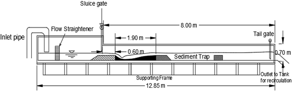
Figure 1. Elevational perspective of experimental flume setup for tests conducted under conditions of free jets.
The corrugated aprons employed in the experiments were constructed from galvanized iron (GI) sheets, featuring various sets of corrugations characterized by wave length (s) and amplitude (t) parameters (dimensions in mm) (65, 15), (70, 15), (70, 20), and (70, 25), as illustrated in Figure 2. The sand properties included a median size (d50) of 1.8 mm, geometric standard deviation (σg) of 1.15, sorting coefficient (So) of 1.06, coefficient of uniformity (Cu) of 1.37, specific gravity of sediment (G) of 2.65, and an angle of repose (ϕ) of 31.5°.
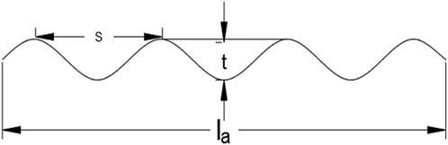
Figure 2. Sketch of apron corrugations.
Under free flow subcritical conditions, discharge remained constant, while variations in tailwater depth were implemented. The sluice gate was fully opened, ensuring that incoming flow remained subcritical (refer to Figure 3). Four different tailwater depths were examined, and for each depth, scour profiles were measured. Scour profiles were delineated on tracing graph paper affixed to the flume glass, as the scour profile was two-dimensional, the jet being 2D, and this scour profile was preserved across the width of the flume. This process was repeated for both smooth and corrugated aprons. In the condition of a submerged hydraulic jump (Figure 3), the tailwater level was determined according to the sequent depth y2 of the hydraulic jump, calculated using the Belanger equation with a known y1 = a (sluice opening). To ensure complete submergence of the hydraulic jump, the tailwater depth was regulated using a tailgate. The tailwater level was gauged at the sediment bed’s end on the sill. Initially, the sand bed was shielded with plywood and secured with weights to prevent displacement. The discharge remained constant, with only adjustments made to the sluice gate opening for each experimental run.
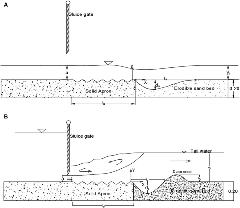
Figure 3. Illustration depicting the definition of scour downstream of a corrugated apron in (A) subcritical free-flow state, and (B) submerged jump condition.
The maximum scour bed was dried and subsequently treated with a synthetic resin-water mixture to reinforce its rigidity. Flow data were collected using an acoustic Doppler velocimeter (ADV) equipped with four probes. The sampling frequency was set to 50 Hz, with a sampling duration of 3–5 min. The stabilization of the scour hole ensured that flow and turbulence characteristics remained consistent.
Initially, the sand bed was covered with plywood and weighted down to prevent displacement. Discharge remained fixed, and only the sluice gate opening was adjusted for each run. Once the desired tailwater depth was attained and flow stabilized, the plywood cover was gently removed ensuring the sand bed remained undisturbed. Variations in the temporal scour profiles were recorded on tracing paper at intervals of 2, 5, 15, 30, 45, 60, 120, and 360 min. The scour profile was two-dimensional, and the smooth rigid apron served as a benchmark for comparing scour behavior under the same flow conditions as observed with corrugated aprons.
The measurement of scour profiles and hydraulic parameters was conducted for at least four sets of upstream gate openings for each corrugated apron model. Discharge was quantified using an ultrasonic flow meter, while flow depth was measured using a pointer gauge with an accuracy of 0.1 mm.
3 Results and discussion
The principal objective of the experiments was to investigate the scour phenomena downstream of corrugated aprons under conditions of a free jet and to examine the turbulence within the scour hole. The impact of different parameters on both scour depth and length was analyzed through graphical representations. Additionally, dimensional analysis was conducted to identify the key parameters influencing the maximum scour depth and length.
3.1 Dimensional analysis
The maximum scour depth (ds) and scour length (ls) downstream of a corrugated apron can be expressed as a function of the following independent variables (Equation 1):
where g is acceleration due to gravity,
Taking
3.2 Scouring process
Free flow conditions, also known as modular flow, prevail downstream of a sluice gate when either the sluice gate is fully opened or when both the sluice gate and tail gate are open, allowing unimpeded flow. In this investigation, only the sluice gate was fully opened to ensure unrestricted flow, while variations in tailwater depth were controlled. For the second phase of experiments for submerged jet, the sluice opening was varied to control the incoming jet Froude number, and tailwater level was increased by operating the tail gate.
3.2.1 Scour profiles
Scouring of the bed occurs when the shear stress exerted by the flowing water jet exceeds the threshold bed shear stress of the sediment particles. The scouring process initiates at the onset of flow and evolves over time until reaching an equilibrium scour profile. Initially, the high shear stress near the bed induces rapid scouring. As the scour depth increases, the shear stress exerted near the bed decreases. In the absence of flow reversal and submergence in free flow jets, dune formation is precluded. The continuous transport of scoured sediment downstream results in the evolution of the scour profile, with the rate of increase in horizontal dimension exceeding that of the vertical dimension. Scour profiles exhibit notable differences between smooth rigid and corrugated aprons, with the latter demonstrating increased scour depth and a shift of the maximum depth towards the upstream region. This contrast is illustrated in Figures 4, 5. Temporal variations in scour depth for both smooth and corrugated aprons indicate a high initial scour rate followed by a gradual decrease over time, as depicted in Figure 6.
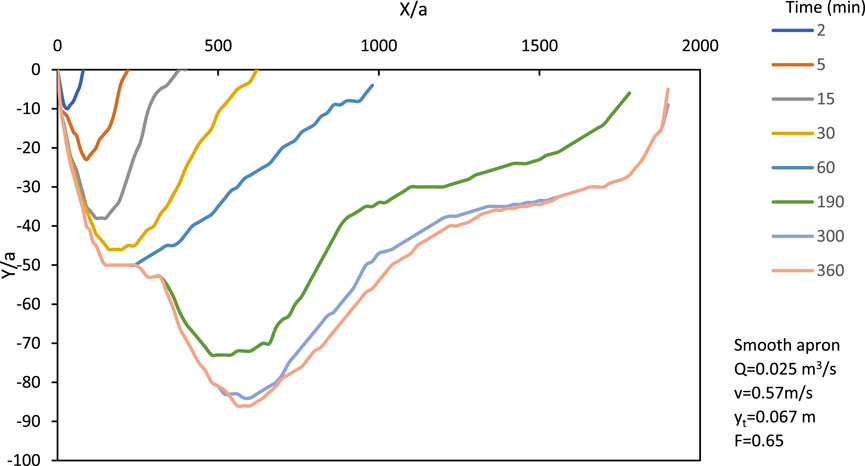
Figure 4. Evolution of scour profile over time until reaching the asymptotic state for smooth apron (free jet).
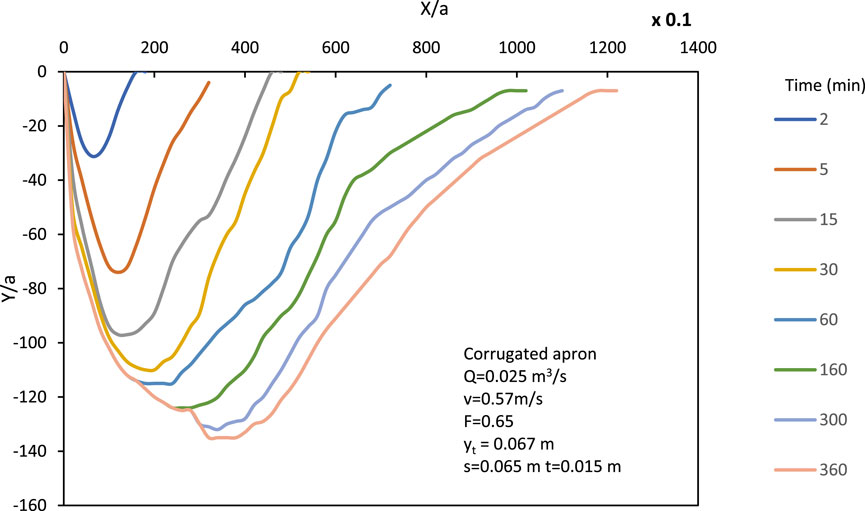
Figure 5. Evolution of scour profile over time until reaching the asymptotic state for corrugated apron (free jet).
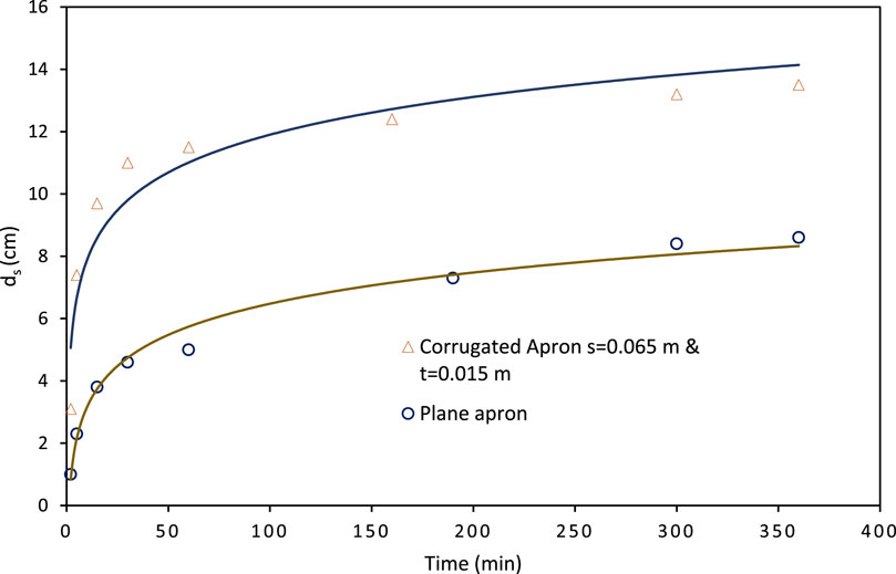
Figure 6. Temporal changes in scour depth for both smooth and corrugated aprons under identical flow conditions (free jet).
Under the condition of a submerged jump, the scour profile exhibits two distinct features: the scour hole and the dune. The formation of the dune is attributed to the flow reversal characteristic of submerged jump conditions. Conversely, dune formation does not occur in free-flow conditions due to the absence of flow reversal and the higher shear stress exhibited by the flowing water. With increasing flow depth, the shear stress exerted by the bottom layer of the fluid becomes significantly lower than that of the top layer, leading to flow separation at the apron’s edge and reattachment of flow at the deepest point of the scour hole. Figure 7 illustrates the temporal scour profiles for a specific flow condition resulting from a smooth apron. Figure 8 displays scour profiles due to a corrugated apron with dimensions s = 0.12 m and t = 0.035 m.
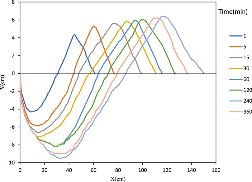
Figure 7. Scour profiles at different time intervals over smooth apron (submerged jet).
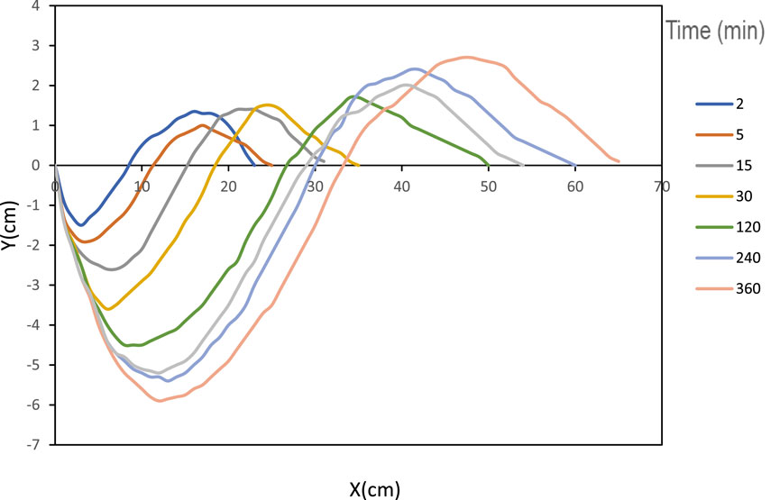
Figure 8. Scour profiles at different times over corrugated apron (submerged jet).
3.2.2 Parameters affecting maximum scour depth
The variation of scour depth with the incoming free jet Froude number F (=
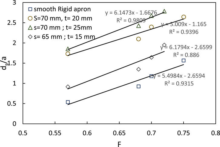
Figure 9. Variation of normalized scour depth ds/a with Froude number F (free jet).
Figure 10 depicts the correlation between the normalized maximum scour depth and the Froude number of submerged jet flow. The graph illustrates the change in normalized scour depth with varying Froude numbers for six distinct corrugated aprons, each characterized by different corrugations, in addition to the result for a smooth apron. As the Froude number rises, the normalized scour depth (ds/a) also increases. This increase is attributable to the increase in the erosive capacity of the jet as a result of higher flow velocity. Faster traversing jets have higher intensity to carry away the sediment. The minimum scour depth is observed for the corrugated apron with s = 70 mm and t = 25 mm.

Figure 10. Variation of normalized scour depth ds/a with Froude number F (submerged jet).
Normalized maximum scour depth was plotted against normalized wavelength (s/a) and amplitude (t/a), revealing an increase in scour depth with increasing values of s/a and t/a, and vice versa (Figures 11, 12). Scour depth increases with increasing wavelength as the erosive capacity of the jet is not diminished appreciably by a corrugation having a higher wavelength when compared to a lower wavelength corrugation of the same horizontal extent. Similar reasons can be attributed to the amplitude as well.
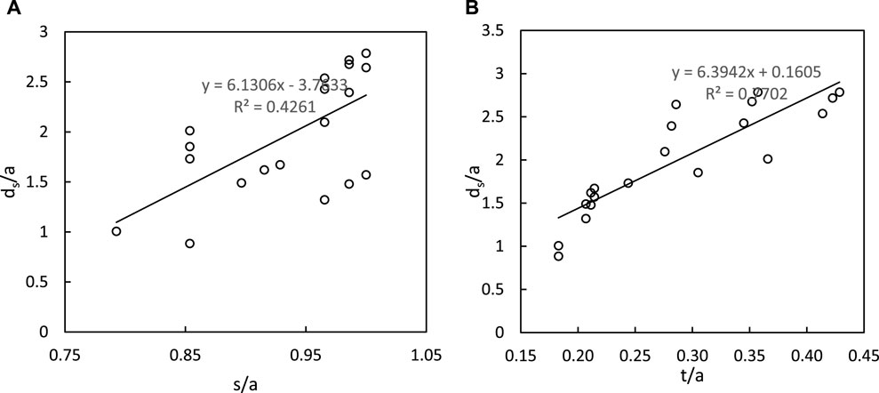
Figure 11. Variation of normalized scour depth ds/a with (A) s/a and (B) t/a (free jet).
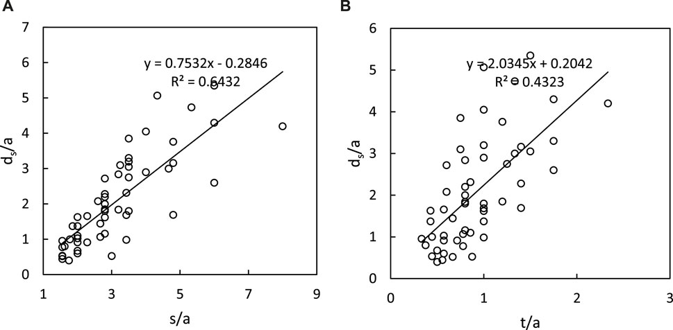
Figure 12. Variation of normalized maximum scour depth ds/a with (A) s/a and (B) t/a (submerged jet).
Figure 13 demonstrates that the normalized scour depth initially decreases gradually with a slight increase in the spacing ratio (s/t). However, further increase in the spacing ratio leads to a rapid de-escalation in the normalized scour depth. This observation conforms with the fact that an increase in the wavelength combined with a simultaneous decrease in the amplitude would decrease the intensity of the jet and hence, the scour depth is reduced.
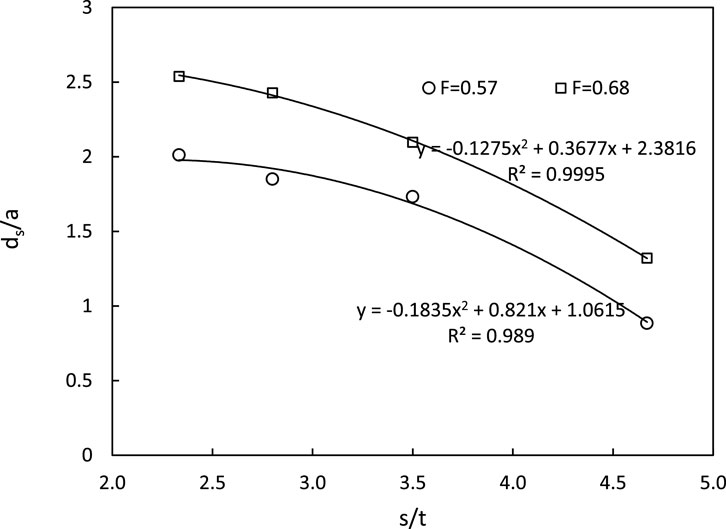
Figure 13. Variation of normalized scour depth ds/a with s/t ratio (free jet).
The variation of normalized scour depth with the ratio of corrugation spacing to amplitude (s/t) for corrugations with a wavelength of 70 mm and different amplitudes (t) was examined for submerged jets. Five sets of corrugated aprons with dimensions (s,t) of (70, 15), (70, 20), (70, 25), (70, 30), and (70, 35) were utilized to determine the optimal corrugation dimension for minimizing scour depth. Figure 14 illustrates the relationship between s/t ratio and normalized maximum scour depth. It demonstrates that as the s/t ratio increases, the maximum scour depth decreases until s/t reaches 3.0. Beyond this point, further increase in s/t leads to an increase in ds/a. Thus, at s/t = 3.0, the minimum normalized scour depth is achieved within the tested range of s/t ratios. Ali et al. (2014) similarly concluded that an optimal spacing ratio of s/t = 3 minimizes scour dimensions. Analysis of data from runs over corrugated and smooth aprons revealed a maximum reduction in scour depth and length of 79% and 83%, respectively, for the tested corrugated aprons.
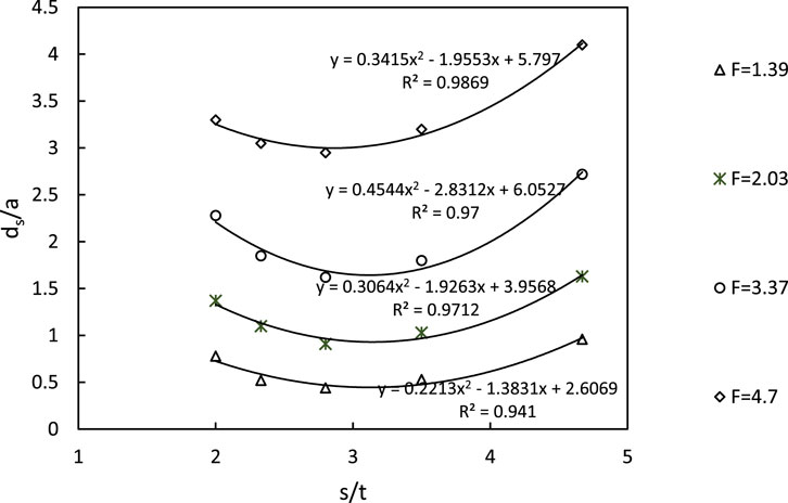
Figure 14. Variation of normalized scour depth ds/a with s/t ratio (submerged jet).
Increasing tailwater depth results in a decrease in scour depth until a limiting tailwater depth is reached, beyond which further increases do not affect scour depth significantly (refer to Figure 15). In contrast, for submerged jets, maximum scour depth is found to be directly proportional to tailwater depth (Figure 16).
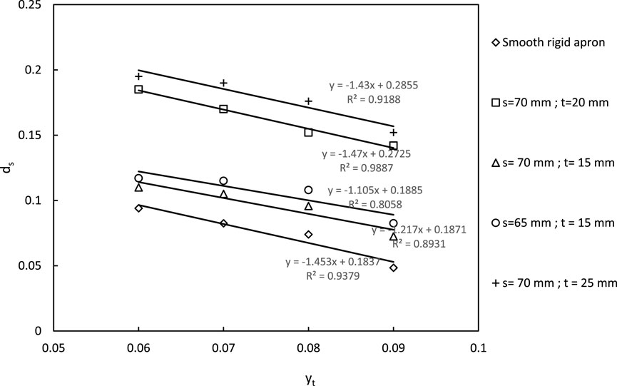
Figure 15. Variation of scour depth ds with tailwater depth yt (free jet).
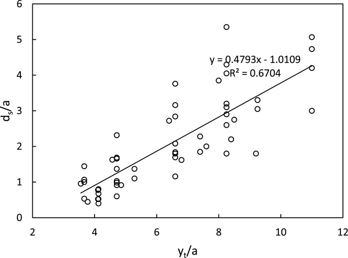
Figure 16. Variation of normalized scour depth ds/a with normalized tailwater depth yt/a (submerged jet).
3.2.3 Distribution of velocity vector in free jets
Velocity vector plots over the apron and within the scour hole, depicted in Figures 17, 18, highlight differences between smooth and corrugated aprons. Magnitude of velocity vector U =
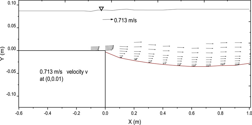
Figure 17. Vector plot illustrating the velocity field within the scour hole with smooth apron (free jet).
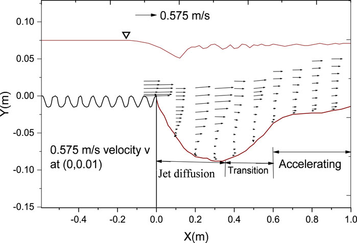
Figure 18. Vector plot illustrating the velocity field within the scour hole with corrugated apron (free jet).
Conversely, in the scour hole downstream of the corrugated apron, a recirculation zone is evident near the bed due to the depth of the scour hole. As the flow exits the apron and enters the scour hole, it diffuses, followed by passage through a transition region with minimal change in velocity vector and magnitude. Subsequently, as the flow exits the scour hole, it begins to accelerate, aided by the decrease in flow depth, thus regaining lost velocity. This behavior is clearly depicted in Figure 18.
3.2.4 Distribution of velocity vector in submerged jets
The velocity over the apron demonstrates a more rapid increase compared to within the scour hole, indicating that the growth rate of the boundary layer on the smooth apron is less than in the scour hole. This observation holds true for both smooth and corrugated aprons. In the case of the smooth apron, resulting in a larger scour hole, the growth rate of the boundary layer was higher than that of the corrugated apron, as velocity decreases with an increase in scour depth.
In Figures 19, 20, the velocity magnitude is higher near the surface of the smooth apron, decreasing upward, and eventually reversing direction. This indicates the presence of a strong roller near the surface of the submerged jet flow. The surface roller extends to a certain distance from the edge of the apron and diminishes towards the downstream direction, resulting in a uniform flow.
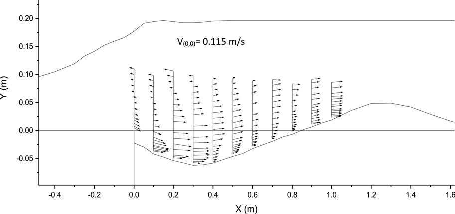
Figure 19. Vector plot illustrating the velocity field within the scour hole with smooth apron (submerged jet).
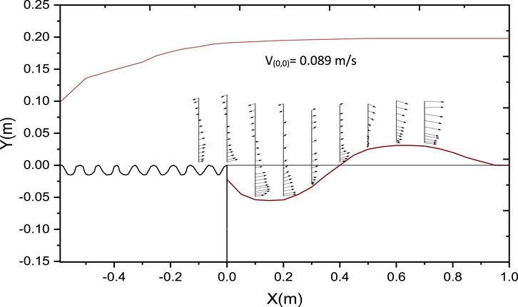
Figure 20. Vector plot illustrating the velocity field within the scour hole with corrugated apron (submerged jet).
Similarly, in the case of the corrugated apron, the length of the jump becomes smaller than that of the smooth apron, and the surface roller is formed up to a shorter distance from the apron compared to the smooth apron.
3.2.5 Distribution of turbulence intensity for free jets
Vertical profile depicting the normalized turbulence intensity within scour hole for both smooth and rough apron was plotted as shown in Figure 21. Horizontal normalized turbulence intensity TIu =
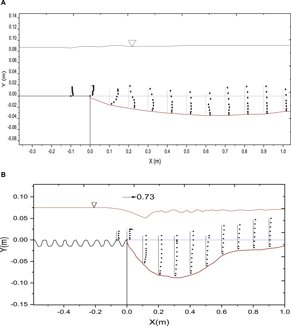
Figure 21. Vertical profile depicting the normalized turbulence intensity TIu within scour hole for (A) smooth apron, and (B) corrugated apron (free jet).
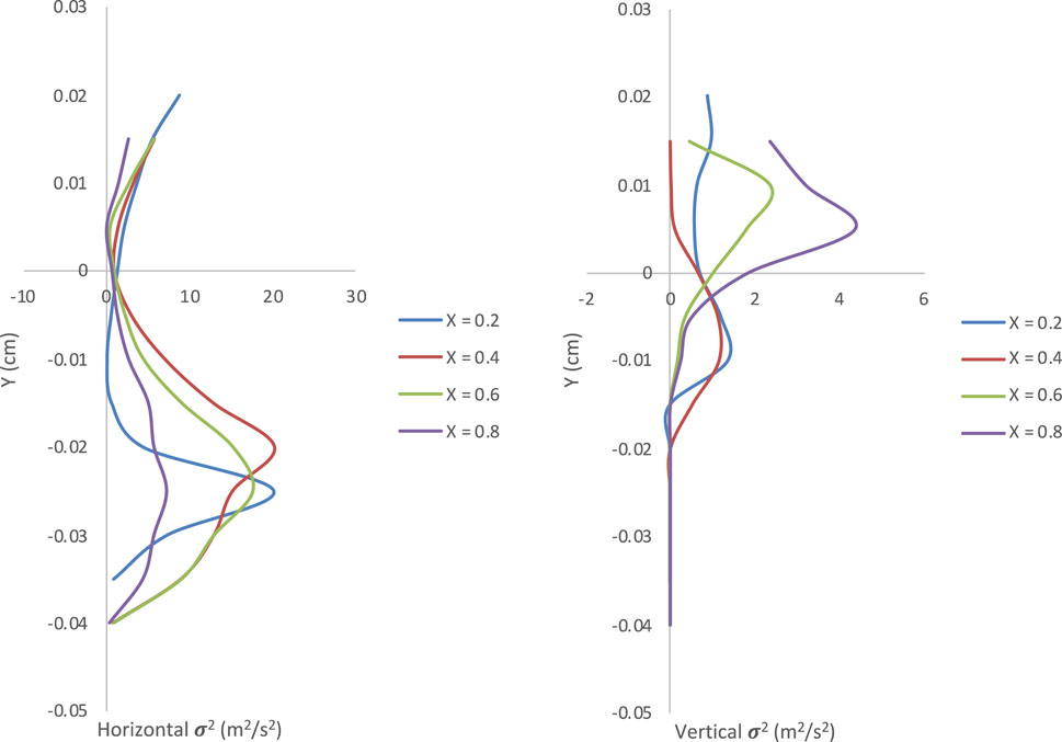
Figure 22. Vertical profiles of horizontal and vertical speed variance σ2.
3.2.6 Distribution of turbulence intensity for submerged jets
Vertical profile depicting the normalized turbulence intensity within scour hole for both smooth and rough apron was plotted as shown in Figures 23, 24. Horizontal normalized turbulence intensity TIu =
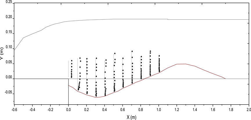
Figure 23. Vertical profile depicting the normalized turbulence intensity TIu within scour hole for smooth apron (submerged jet).
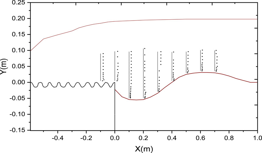
Figure 24. Vertical profile depicting the normalized turbulence intensity TIu within scour hole for corrugated apron (submerged jet).
4 Conclusions
Experiments conducted under free flow conditions for scour downstream of corrugated aprons reveal several key findings:
• Corrugated aprons induce greater scour depths compared to smooth aprons under free flow conditions, primarily due to higher turbulence intensity.
• The optimal spacing ratio (s/t) for submerged jets is determined to be 3, at which both scour depth and length are minimized. This spacing ratio facilitates maximum dissipation of energy.
• The maximum reduction in scour depth and length was determined to be 79% and 83%, respectively, while the minimum reduction in scour depth and length was found to be 13% and 11%, respectively, for the tested corrugated aprons.
• The scour profiles downstream of corrugated aprons exhibit distinct regions, including jet diffusion, transition, acceleration, and recirculation zones near the bed.
• Despite higher turbulence intensity near the surface, smooth aprons result in faster increases in turbulence intensity within the scour hole compared to corrugated aprons.
• Careful consideration should be given to flow conditions, particularly during maintenance periods when sluice gates are fully opened, as this can exacerbate scouring near hydraulic structures.
• Turbulence intensity and bed shear stress are identified as critical factors governing scour profiles under free flow conditions.
Data availability statement
The original contributions presented in the study are included in the article/supplementary material, further inquiries can be directed to the corresponding author.
Author contributions
MM: Conceptualization, Data curation, Formal Analysis, Funding acquisition, Investigation, Methodology, Writing–original draft, Writing–review and editing. ME: Formal Analysis, Investigation, Supervision, Validation, Writing–review and editing. MF: Investigation, Methodology, Supervision, Validation, Writing–review and editing. MS: Formal Analysis, Investigation, Methodology, Writing–review and editing.
Funding
The author(s) declare that financial support was received for the research, authorship, and/or publication of this article. This work was supported and funded by the Deanship of Scientific Research at Imam Mohammad Ibn Saud Islamic University (IMSIU) (grant number IMSIU-RG23139).
Conflict of interest
The authors declare that the research was conducted in the absence of any commercial or financial relationships that could be construed as a potential conflict of interest.
Publisher’s note
All claims expressed in this article are solely those of the authors and do not necessarily represent those of their affiliated organizations, or those of the publisher, the editors and the reviewers. Any product that may be evaluated in this article, or claim that may be made by its manufacturer, is not guaranteed or endorsed by the publisher.
References
Aamir, M., and Ahmad, Z. (2015). “Estimation of scour depth downstream of an apron under 2D horizontal jets,” in Proceedings of HYDRO 2015 International, 20th International Conference on Hydraulics, Water Resources and River Engineering, India, 19th December 2015 (Indian Institute of Technology Roorkee).
Aamir, M., and Ahmad, Z. (2016). Review of literature on local scour under plane turbulent wall jets. Phys. Fluids 28, 105102. doi:10.1063/1.4964659
Aamir, M., and Ahmad, Z. (2017). “Prediction of local scour depth downstream of an apron under wall jets,” in Development of water resources in India. Water science and Technology library. Editors V. Garg, V. Singh, and V. Raj (Cham: Springer), 75, 375–385. doi:10.1007/978-3-319-55125-8_32
Aamir, M., and Ahmad, Z. (2019). Estimation of maximum scour depth downstream of an apron under submerged wall jets. J. Hydroinformatics 21 (4), 523–540. doi:10.2166/hydro.2019.008
Aamir, M., Ahmad, Z., Pandey, M., Khan, M. A., Aldrees, A., and Mohamed, A. (2022). The effect of rough rigid apron on scour downstream of sluice gates. Water 14 (14), 2223. doi:10.3390/w14142223
Aderibigbe, O., and Rajaratnam, N. (1998). Effect of sediment gradation on erosion by plane turbulent wall jets. J. Hydraulic Eng. 124 (10), 1034–1042. doi:10.1061/(asce)0733-9429(1998)124:10(1034)
Ali, H. M., El Gendy, M. M., Mirdan, A. M. H., Ali, A. A. M., and Abdelhaleem, F. S. F. (2014). Minimizing downstream scour due to submerged hydraulic jump using corrugated aprons. Ain Shams Eng. J. 5 (4), 1059–1069. doi:10.1016/j.asej.2014.07.007
Ali, K. H. M., and Lim, S. Y. (1986). Local scour caused by submerged wall jets. Proc. Institution Civ. Eng. 81 (2), 607–645. doi:10.1680/iicep.1986.464
Basiouny, M. E., Nasrallah, T. H., Abdelhaleem, F. S., and Ibraheem, A. S. (2018). “Roughened and Corrugated aprons as scour countermeasure downstream of submerged hydraulic jump,” in Twenty-first International Water Technology Conference, China, Feb 15, 2018 (IWTC21), 200–214.
Chatterjee, S. S., and Ghosh, S. N. (1980). Submerged horizontal jet over erodible bed. J. Hydraulics Div. 106 (11), 1765–1782. doi:10.1061/jyceaj.0005556
Chatterjee, S. S., Ghosh, S. N., and Chatterjee, M. (1994). Local scour due to submerged horizontal jet. J. Hydraulic Eng. 120 (8), 973–992. doi:10.1061/(asce)0733-9429(1994)120:8(973)
Chiew, Y. M., and Parker, G. (1994). Incipient sediment motion on non-horizontal slopes: Début d’entraînement de sédiments sur des lits non horizontaux. J. Hydraulic Res. 32 (5), 649–660. doi:10.1080/00221689409498706
Dey, S., and Sarkar, A. (2006). Scour downstream of an apron due to submerged horizontal jets. J. Hydraulic Eng. 132 (3), 246–257. doi:10.1061/(asce)0733-9429(2006)132:3(246)
Dey, S., and Sarkar, A. (2008). Characteristics of turbulent flow in submerged jumps on rough beds. J. Eng. Mech. 134 (7), 49–59. doi:10.1061/(asce)0733-9399(2008)134:1(49)
Dey, S., Sarkar, S., and Solari, L. (2011). Near-bed turbulence characteristics at the entrainment threshold of sediment beds. J. Hydraulic Eng. 137 (9), 945–958. doi:10.1061/(asce)hy.1943-7900.0000396
Ead, S. A., and Rajaratnam, N. (2002). Hydraulic jumps on corrugated beds. J. Hydraulic Eng. 128 (7), 656–663. doi:10.1061/(asce)0733-9429(2002)128:7(656)
Ead, S. A., Rajaratnam, N., Katopodis, C., and Ade, F. (2000). Turbulent open channel flow in circular corrugated culverts. J. Hydraulic Eng. 126 (October), 750–757. doi:10.1061/(asce)0733-9429(2000)126:10(750)
Farhoudi, J., and Smith, K. V. H. (2010). Local scour profiles downstream of hydraulic jump. J. Hydraulic Res. 23 (4), 343–358. doi:10.1080/00221688509499344
Guan, D., Melville, B. W., and Friedrich, H. (2014). Flow patterns and turbulence structures in a scour hole downstream of a submerged weir. J. Hydraulic Eng. 140 (1), 68–76. doi:10.1061/(asce)hy.1943-7900.0000803
Hassan, N. M. K. N., and Narayanan, R. (1985). Local scour downstream of an apron. J. Hydraulic Eng. 111 (11), 1371–1385.
Helal, E. Y., Nassralla, T. H., and Abdelaziz, A. A. (2013). Minimizing of scour downstream hydraulic structures using sills. Int. J. Civ. Struct. Eng. 3 (3).
Peterka, A. J. (1984). Hydraulic design of stilling basins and energy dissipators. China: Bureau of Reclamation.
Keywords: apron, Froude number, scour, jets, hydraulic jump, turbulence
Citation: Mumtaz MA, Elgamal MH, Farouk MI and Siddiqui MIH (2024) Hydraulic erosion patterns downstream of corrugated aprons: investigating free and submerged jet effects. Front. Environ. Eng. 3:1446683. doi: 10.3389/fenve.2024.1446683
Received: 10 June 2024; Accepted: 26 July 2024;
Published: 14 August 2024.
Edited by:
Sandhya Patidar, Heriot-Watt University, United KingdomReviewed by:
Ajey Kumar Patel, National Institute of Technology Warangal, IndiaAnnalisa Di Bernardino, Sapienza University of Rome, Italy
Copyright © 2024 Mumtaz, Elgamal, Farouk and Siddiqui. This is an open-access article distributed under the terms of the Creative Commons Attribution License (CC BY). The use, distribution or reproduction in other forums is permitted, provided the original author(s) and the copyright owner(s) are credited and that the original publication in this journal is cited, in accordance with accepted academic practice. No use, distribution or reproduction is permitted which does not comply with these terms.
*Correspondence: Mohd Aamir Mumtaz, bW1hYW1pckBpbWFtdS5lZHUuc2E=