 Lu Ma
Lu Ma Yijia Li2
 Le Zhou
 Xin Shen
94% of researchers rate our articles as excellent or good
Learn more about the work of our research integrity team to safeguard the quality of each article we publish.
Find out more
ORIGINAL RESEARCH article
Front. Energy Res., 24 March 2025
Sec. Wind Energy
Volume 13 - 2025 | https://doi.org/10.3389/fenrg.2025.1571567
Introduction: The trend toward larger wind turbine has made the aeroelastic issues of the wind turbine blades more prominent. To investigate the effect of flexible deflection of hundred-meter-scale blades on wind turbine performance.
Methods: The present study taking the IEA-15 MW wind turbine as the research object, and the aeroelastic coupling characteristics of the wind turbine under yaw condition are analyzed using the lifting-line free vortex wake model and a geometrically exact beam theory model.
Results and Discussion: The results show that, the torsional deflection of the blades may cause the reduction of the angle of attack, leading to the decrease of the wind turbine loads. Furthermore, influenced by the additional velocity induced by blade flapwise deflection, the loads fluctuation of flexible blade is larger than those of rigid blade. As the yaw angle increases, the mean power of the wind turbine decreases, while the fluctuation amplitude increases. Besides, the mean value and fluctuation amplitude of the rotor tilt and yaw moments become larger, the angle of attack exhibits more significant fluctuation amplitude but reduced mean value, and the turbine wake contracts and skews more obviously.
Under the trend of size increasing of wind turbines, blades become slender, with the length of ultra-large wind turbine blades now exceeding 100 m. The flexible deflection of the blade has a non-negligible impact on the load characteristics of wind turbine. Besides, wind turbines usually operate under unsteady inflow conditions, such as atmospheric turbulence (Ramos-García et al., 2022; Dangi et al., 2025), wind shear (Zhang et al., 2022; Wang et al., 2024; Zhang et al., 2014), and yaw misalignment (Xiao et al., 2025; Leng et al., 2024), which can lead to complex aeroelastic coupling issues. A thorough analysis of the aeroelastic coupling behavior of wind turbine under complex operating conditions is of significant importance for optimizing design, extending fatigue life, and ensuring stable operation of the wind turbine.
Currently, the commonly used methods for predicting the aerodynamic performance of wind turbine primarily include the blade element momentum (BEM) theory method (Amoretti et al., 2023; Özkan and Genç, 2023; Ghandour et al., 2022), computational fluid dynamics (CFD) method (Ye et al., 2024; Duan et al., 2022; Fu et al., 2023), and vortex wake theory method (Corniglion et al., 2020; Rodriguez and Jaworski, 2019; Sebastian and Lackner, 2012; Xu et al., 2019). Among these, the BEM theory method is a quasi-steady approach and has limited predictive capability for the performance of wind turbine under unsteady operating conditions. While CFD method can provide relatively accurate predictions of the unsteady aerodynamic performance of wind turbines, it requires substantial computational resources. Vortex wake theory method, based on potential flow assumptions, can account for the realistic shape of the rotor wake and shows good applicability for unsteady conditions, achieving a favorable balance between computational accuracy and efficiency.
On the structural side, commonly used methods include the finite element method (FEM), multi-body dynamics method, and one-dimensional equivalent beam method. The finite element method offers high computational accuracy, but the blade modeling process is complex and requires significant computational resources. Multi-body dynamics method divides the blade into several virtually connected segments, requiring fewer degrees of freedom and offering higher computational efficiency compared to FEM. The equivalent beam method treats the wind turbine blade as a cantilever beam for modeling, providing high computational efficiency. When higher-order models are employed for blade modeling, the equivalent beam method can achieve computational accuracy comparable to that of FEM. As a result, mainstream wind turbine industry software often adopts this method for blade structural modeling.
By coupling different aerodynamic and structural models, researchers have developed various aeroelastic coupling programs and applied them to study the aeroelastic behavior of wind turbines. Larsen, (2004) highlighted that during wind turbine operation, blade bending reduces the effective swept area of the rotor, leading to a decrease in rotor power. Carrión et al. (2014) employed the CFD-MBD method to conduct aeroelastic simulations of the MEXICO rotor. Their results indicated that blade torsional stiffness influences torsional deflection, thereby affecting wind turbine performance. Conversely, Yu and Kwon, (2014), based on the CFD-FEM approach, conducted aeroelastic simulations of the NREL-5 MW blade and the results show that under aerodynamic loading, the blade undergoes torsional deflection in the nose-down direction, resulting in a significant reduction in aerodynamic loads. For floating platform conditions, Kim and Kwon, (2019) used a BEM model and a nonlinear Euler-Bernoulli beam model to investigate the aeroelastic response of the NREL-5 MW wind turbine under surge and pitch motions. Their findings revealed that blade loads and deflections exhibit periodic fluctuations under these conditions, and torsional deflection reduces blade loads. Similarly, Liu et al., (2019) applied the CFD-MBD model to study the aeroelastic coupling characteristics of a floating wind turbine under surge motion, reaching similar conclusions.
Although the aforementioned studies have identified the impact of blade elastic deflection on wind turbine performance, there remains a lack of in-depth analysis, particularly under complex inflow conditions where the aeroelastic coupling behavior of wind turbines becomes more intricate. The various influencing factors and their mechanisms require further investigation. Moreover, most existing aeroelastic studies focus on the NREL-5 MW wind turbine (with a blade length of 61.5 m), for which the influence of blade deflection is relatively limited compared to future mainstream 15 MW-class wind turbines (with blade length exceeding 100 m). Therefore, research on the aeroelastic coupling characteristics of 15 MW-class wind turbines holds greater relevance for the development of current large-scale wind turbines.
In light of this, this present study focuses on the IEA-15 MW wind turbine to investigate its aeroelastic coupling behavior under yaw conditions. Additionally, to improve the accuracy of predicting unsteady aerodynamic characteristics and nonlinear blade deflection, while accounting for the distortion of the rotor wake under yaw conditions, this study employs an aeroelastic coupling model based on vortex wake theory and geometrically exact beam theory to conduct the numerical simulation.
This study adopts the lifting-line free vortex wake (LL-FVW) model for aerodynamic analysis (Sebastian and Lackner, 2012; Shen et al., 2018; Shen et al., 2015). In the LL-FVW model, the blade is represented by a bound vortex filament positioned at the quarter-chord line relative to the blade’s leading edge. The bound vortex is discretized into multiple spanwise segments along the blade, with each segment shedding trailing vortices that extend downstream into the wake. The circulation distribution along the blade can be determined iteratively using Equation 1:
where,
where,
Furthermore, as the wake of the rotor undergoes dynamic evolution under unsteady operating conditions, it is necessary to solve the vortex dynamics equation shown in Equation 3 to determine the shape of the rotor wake at different time steps:
where
The Beddoes-Leishman (B-L) based dynamic stall model is adopted to simulate the unsteady aerodynamics of the airfoil in the present study, and detailed introduction of the model can refer to Ref. (Leishman, 2002; Leishman and Beddoes, 1989).
This study employs geometrically exact beam theory (Bauchau, 2011; Hodges, 2006; Hodges, 2009; Chen et al., 2019a; Chen et al., 2019b) to predict the blade structural deflections under yaw condition. Based on Hamilton’s principle, the governing equations of the beam are established. For the wind turbine blade, the relationship between stress and strain at each cross-section can be expressed as Equation 4:
where,
Therefore, the strain energy of the blade deflection can be expressed as Equation 5:
Therefore, the strain energy of the blade deflection can be expressed as Equation 6:
where,
Based on Hamilton’s principle, the governing equation for the wind turbine blade can be expressed as Equation 8:
where,
This study selects the IEA-15 MW wind turbine as the research object. The IEA-15 MW is an upwind, horizontal-axis wind turbine featuring a rotor diameter of 240 m, a hub height of 150 m, and blade length of 117 m. The turbine is mounted on a monopile foundation with a diameter of 10 m, suitable for a water depth of 30 m and a burial depth of 45 m below the seabed. The cut-in and cut-out wind speeds are 3 m/s and 25 m/s respectively, and the rated wind speed is 10.59 m/s. The rated rotational speed is 7.55 rpm, and the design tip-speed ratio is 9. Basic parameters of the IEA-15 MW wind turbine are listed in Table 1 (Gaertner et al., 2020). The spanwise distribution of the flapwise, edgewide, tortional and tension stiffness along the IEA-15 MW blade are shown in Figure 1.
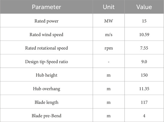
Table 1. Basic parameters of the IEA-15 MW wind turbine.
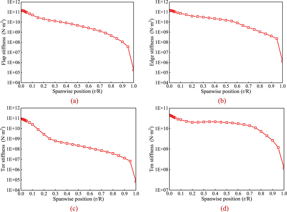
Figure 1. Spanwise distribution of the stiffness along the blade. (a) Flapwis. (b) Edgewise. (c) Torsional. (d) Tension.
In the present study, the lifting-line free vortex wake method is verified by comparing the power and thrust of the IEA-15 MW RWT under wind velocity from 3 m/s to 25 m/s calculated by the present method with the data provided in IEA-15 MW RWT technical report (Gaertner et al., 2020). The comparison results show that the results given by lifting-line free vortex wake method used in the present study is reliable (as shown in Figure 2).
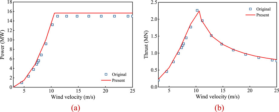
Figure 2. Verification of the lifting-line free vortex wake method. (a) Power. (b) Thrust.
The geometrically exact beam theory method is verified by comparing the natural frequency of the IEA-15MW blade calculated through the present method with the results from other methods, the comparison data are given Table 2. The data in Table 2 indicates that the results given by geometrically exact beam theory method used in the present study is reliable.
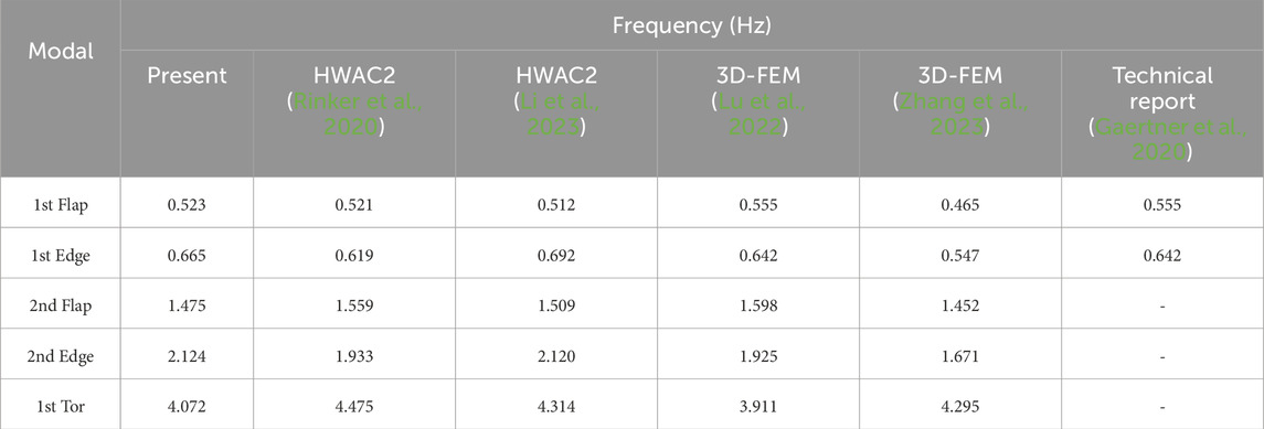
Table 2. Comparison of natural frequencies of the IEA-15 MW blade.
Under practical operation conditions, wind turbines often operate under unsteady inflow conditions with continuously changing wind directions. Consequently, the rotor is frequently unable to align perfectly with the incoming wind, resulting in a yaw misalignment. The yaw condition refers to an operation state under which the rotational plane of the rotor forms an angle with the incoming wind direction, known as the yaw angle. As illustrated in Figure 3, θyaw represents the yaw angle, while
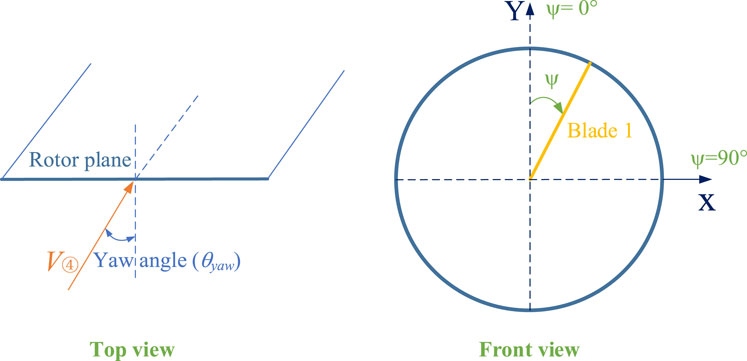
Figure 3. Schematic of inflow to the wind turbine under yaw condition.
Under yaw condition, the normal inflow velocity does not vary with the azimuth angle. However, due to the yaw angle between the rotor plane and the inflow wind direction, the tangential inflow velocity fluctuates periodically with the rotation of the blade. Figure 4 illustrates the velocity triangle at the airfoil section under yaw condition. It is evident that the normal inflow velocity does not vary with the azimuth angle, whereas the tangential inflow velocity includes components related to the azimuth and yaw angles, exhibiting periodic harmonic fluctuations with the blade rotation. These fluctuations directly result in periodic changes in angle of attack experienced of the blade, and affect the loads response of the wind turbine.
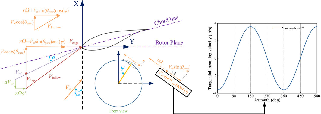
Figure 4. Schematic of velocity triangle at blade section under yaw condition.
The periodic fluctuation of inflow velocity has significant effects on the load characteristics of the blade and rotor. To highlight the impact of aeroelastic coupling effects of flexible blades on wind turbine performance under yaw condition, this section assumes that the wind turbine operates at a rated operation point without considering pitch control, and a yaw angle of 20° is selected for the study. Figure 5 presents the variation curves of rotor loads with azimuth angle under both steady inflow condition and yaw condition, including rotor power, thrust, and tilt and yaw moments, comparing cases with and without blade flexibility.
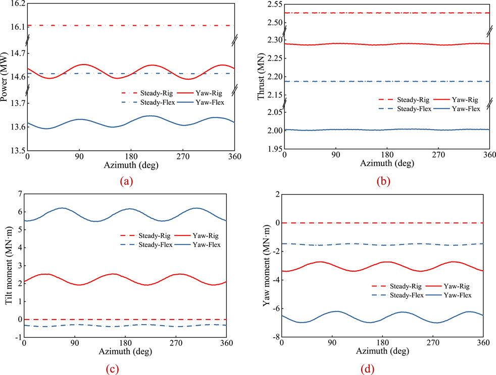
Figure 5. Characteristics of wind turbine load with azimuth angle under yaw condition. (a) Power. (b) Thrust. (c) Tilt moment. (d) Yaw moment.
As shown in Figures 5A, B, the periodic variation of tangential inflow velocity results in harmonic oscillations in wind turbine power and thrust with the azimuth angle. Under yaw condition, both the mean values and fluctuation amplitudes of the wind turbine’s power and thrust are lower than those under uniform inflow conditions. When considering blade flexibility, the torsional deflection of the blades reduces the effective angle of attack, further reducing the mean values of turbine power and thrust. Figures 5C, D show the variation curves of tilt and yaw moments with azimuth angle under yaw condition. It can be observed that both rigid-blade and flexible-blade rotors exhibit tilt and yaw moments. The mean tilt moment is positive, while the mean yaw moment is negative. Furthermore, the absolute mean values of the tilt and yaw moments for the flexible-blade rotor are greater than those for the rigid-blade rotor.
The fluctuation of rotor loads is closely related to the periodic loads experienced by the blades under yaw condition. Figures 6A, B illustrate the variation characteristics of normal and tangential forces with the azimuth angle for rigid and flexible blades under yaw condition. It can be observed that, within the azimuth angle range of 0°–180°, the mean normal force on each blade section is lower than that in the 180°–360° range, resulting in a yaw moment for both rigid and flexible blade rotors. Due to the further intensification of load distribution non-uniformity in flexible blades, the difference in mean thrust between the two azimuth angle ranges (0°–180° and 180°–360°) increases significantly, leading to a higher yaw moment for flexible blade.
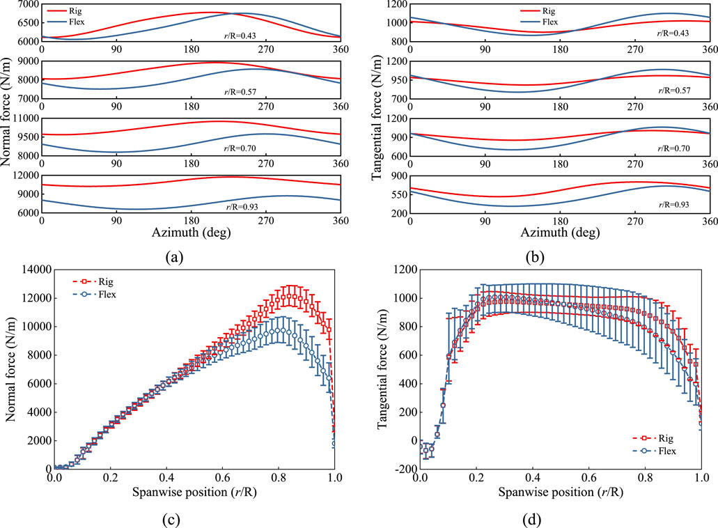
Figure 6. Characteristics of force variation at different blade sections under yaw condition. (a) Normal force-periodic. (b) Tangential force-periodic. (c) Normal force-spanwise. (d) Tangential force-spanwise.
Figures 6C, D show the spanwise distribution of normal and tangential forces for rigid and flexible blades under yaw condition. It is observed that, compared to rigid blade, the mean loads of flexible blades are reduced, particularly near the blade tip region, where this phenomenon becomes more pronounced. Besides, the fluctuation amplitude of loads on flexible blade is significantly higher than that of rigid blade under yaw condition.
The angle of attack is a key factor determining the aerodynamic load distribution along the spanwise sections of the blade. Figure 7 presents the variation curves and spanwise distribution of the angle of attack with azimuth angle for rigid and flexible blades. As shown in Figure 7A, the angle of attack for both rigid and flexible blades exhibits similar harmonic oscillations with azimuth angle. At an azimuth angle of 0°, the angle of attack is noticeably higher than at 180°, which is due to the distribution of tangential inflow velocity at the blade sections under yaw condition. As analyzed previously (Figure 4), the tangential inflow velocity at 180° is higher than at 0°, leading to a lower angle of attack at 180° compared to 0°. Additionally, in the azimuth angle range from 270° to 360°, the mean angle of attack for both rigid and flexible blades is higher. As the spanwise position increases, the difference in angle of attack between the rigid and flexible blades gradually increases, with the angle of attack of the flexible blade showing a decreasing trend. From Figure 7B, it can be observed that, starting at 40% of the blade span, the mean angle of attack for the flexible blade is lower than that for the rigid blade, and it further decreases with increasing spanwise position. However, the fluctuation amplitude of the angle of attack for the flexible blade is higher than that of the rigid blade. The phenomenon of increased load fluctuation in flexible blades will be further analyzed in subsequent sections.
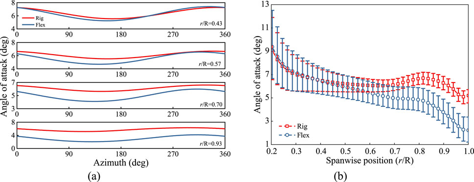
Figure 7. Characteristics of blade angle of attack at different sections under yaw condition. (a) Periodic. (b) Spanwise.
As previously analyzed, the tangential induced velocity is smaller than the normal induced velocity and has a negligible effect on the angle of attack when combined with the rotational linear velocity of the rotor, thus it can be ignored. Therefore, the focus is placed on analyzing the influence of the normal induced velocity. Figure 8 presents a spanwise distribution contour map of the blade normal induced velocity. It can be observed that, under yaw condition, the normal induced velocity on the right half-plane of the rotor for both rigid and flexible blades is generally higher, particularly in the spanwise region from 80% to 100% of the blade span. Moreover, the normal induced velocity at 90° azimuth is significantly greater than at 270°, and if only the variation in normal induced velocity is considered, the angle of attack at 90° azimuth is lower than at 270°, which is consistent with the angle of attack distribution results shown in Figure 7.
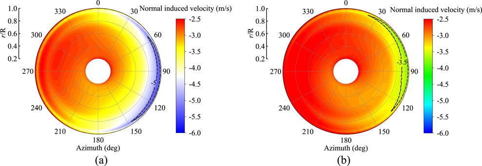
Figure 8. Contour of blade normal induction velocity with azimuth angle under yaw condition. (a) Rigid. (b) Flexible.
Figure 9 presents a top-down view of the wake profile of the rotor under yaw condition. From the figure, it can be seen that there are differences between the rigid and flexible blades in terms of wake structure and propagation characteristics. The wake structure of the rigid blade is more compact and regular, with smaller wake spacing, and shorter propagation distances. In contrast, the wake structure of the flexible blade is relatively sparse, with the wake diffusing more rapidly during propagation and larger wake spacing. Notably, at 90° azimuth, the blade is able to penetrate more deeply into the wake region, resulting in a stronger induction effect. As a result, the normal induced velocity at 90° azimuth is larger than that at 270° azimuth.
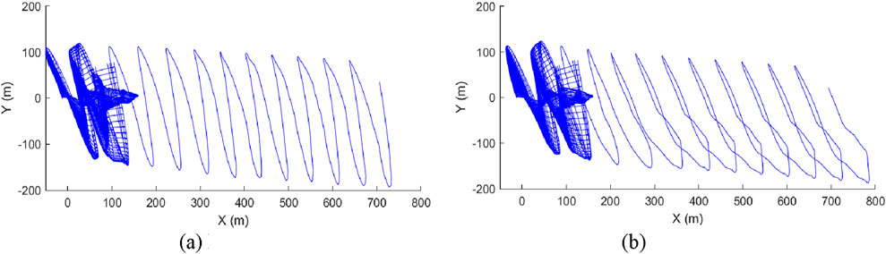
Figure 9. Wake profile of the wind rotor under yaw condition (top view). (a) Rigid. (b) Flexible.
When a wind turbine operates under yaw inflow condition, the blade will experience load fluctuations that differ from those in steady inflow, leading to blade deflection. The deformed blades, in turn, further influence the turbine’s load performance. During operation, the blades undergo deflection in three directions, namely, flapwise, edgewise, and torsional directions in Figure 10. Flapwise deflection refers to the bending of the blade perpendicular to the rotor plane, with its positive direction pointing downstream of the turbine. Edgewise deflection is bending within the rotor plane, with the positive direction pointing towards the trailing edge of the airfoil. Torsional deflection represents the twisting of the blade around its elastic axis, with its positive direction causing the airfoil section to rotate toward the stall direction. The additional velocities induced by the blade’s flapwise and edgewise deflections may influence the inflow velocity experienced by the blade, leading to changes in the angle of attack and affecting the turbine’s aerodynamic performance. At the same time, torsional deflection directly modifies the angle of attack, further influencing the turbine’s overall performance.
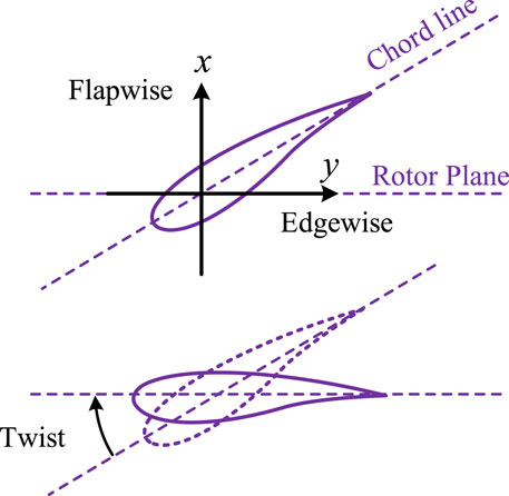
Figure 10. Illustration of the blade flapwise bending, edgewise bending and twist deflections.
Figure 11 presents the deflection contour maps of the blade, including flapwise, edgewise, and torsional deflections. It can be observed that flapwise deflection is primarily concentrated in the blade tip region, approximately between 70% and 100% of the span. The flapwise deflection is most significant at the blade tip, reaching about 15 m. Under the influence of yaw condition, flapwise deflection is more pronounced in the left half-plane of the rotor. The edgewise deflection is relatively small, exhibiting larger negative values in the azimuth range of 60°–120°. This is mainly due to the combined effect of gravity and tangential forces acting in the same direction, leading to higher edgewise deflection in this region. Additionally, the edgewise deflection shows an asymmetric distribution across the upper and lower parts of the rotor plane. Torsional deflection is concentrated in the middle to tip regions of the blade (r/R = 0.5–1.0), with a maximum twist angle of about 4°. The overall distribution of torsional deflection is roughly symmetrical in the azimuth range of 120°–300°, with larger torsional deflection observed in the left half-plane of the rotor.
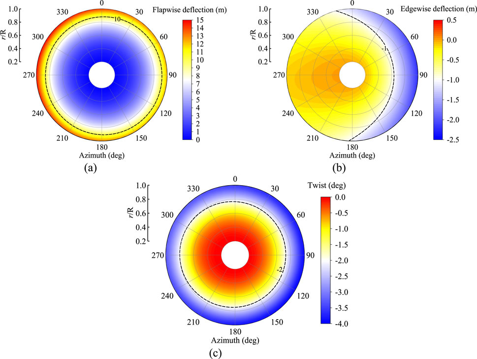
Figure 11. Contour of blade deflection with azimuth angle under yaw condition. (a) Flapwise. (b) Edgewise. (c) Tortional.
From the above analysis, it can be observed that due to the influence of blade flexibility, the blade experiences load reduction. Under the influence of aerodynamic loads, flexible blades undergo torsional deflection in the direction of reduced angle of attack, which lowers the effective angle of attack and impacts the overall load on the wind turbine. Figures 12A, B show the distribution of the angle of attack with spanwise position for rigid and flexible blades at 0° and 180° azimuth angles, as well as the spanwise distribution of torsional deflection for the flexible blade. It can be observed that as the spanwise position increases, the torsional deflection of the flexible blade increases. At the same spanwise positions, the angle of attack for the flexible blade is always smaller than that for the rigid blade. This is because, after being subjected to aerodynamic loads, the flexible blade twists in the nose-down direction, which reduces the effective angle of attack and consequently decreases the aerodynamic load on the blade. Therefore, the mean load on the flexible blade is lower than that on the rigid blade.
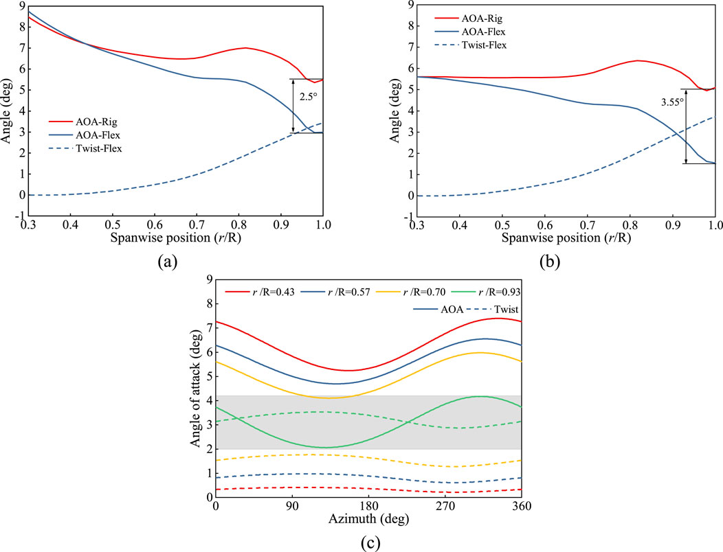
Figure 12. Characteristics of blade angle of attack and twisting deflection under yaw condition. (a) Spanwise-Azimuth 0°. (b) Spanwise-Azimuth 180°. (c) Periodic.
Near the blade tip, the effect of torsional deflection on the reduction of the effective angle of attack is more pronounced, with the maximum difference in angle of attack between the rigid and flexible blades reaching 2.5° and 3.55° at the blade tip for 0° and 180° azimuth angles, respectively. It is important to note that at 0° and 180° azimuth angles, the torsional deflection across the blade sections is similar, but there is a significant difference in the angle of attack at the blade tip between the rigid and flexible blades. This suggests that, in addition to the direct effect of torsional deflection on the angle of attack, the additional velocities due to flapwise and edgewise deflections also have a significant impact on the angle of attack. Figure 12C presents the variation curves of the angle of attack and torsional deflection with azimuth angle, where the solid line represents the angle of attack and the dashed line represents the absolute value of the torsional deflection. It can be observed that as the spanwise position increases, the angle of attack gradually decreases, while torsional deflection gradually increases. Near the blade tip, the torsional deflection can reach 3°–3.5°, which significantly impacts the angle of attack. Moreover, as the torsional deflection gradually increases, the angle of attack shows a significant decreasing trend, with more pronounced characteristics at the 120° azimuth angle. Conversely, when the torsional deflection gradually decreases, the angle of attack increases, with notable characteristics at the 330° azimuth angle. Thus, the downward torsional deflection of flexible blades reduces the angle of attack, and the periodic fluctuations in torsional deflection further amplify the oscillation amplitude of the angle of attack to some extent. However, compared to torsional deflection, the angle of attack exhibits more pronounced fluctuations with respect to the azimuth angle. This is because the additional velocity also causes variations in the angle of attack, exerting a more significant influence.
The flapwise and edgewise deflections of the blade introduce additional velocities in the normal and tangential directions. These velocities alter the velocity triangle at the blade sections, thus affecting the temporal fluctuations of the angle of attack. Based on the previous analysis, although torsional deflection can significantly reduce the effective angle of attack, its fluctuation amplitude is relatively small, and therefore, it is not the main factor influencing the angle of attack fluctuations of the flexible blade. Furthermore, the fluctuation of normal induced velocity in flexible blades is smaller than that in rigid blades. As a result, it is necessary to focus on the effect of additional velocities on the angle of attack fluctuations for flexible blades.
Figure 13 presents the variation curves of flapwise and edgewise velocities with azimuth angle. Under yaw condition, both flapwise and edgewise velocities exhibit clear periodic fluctuations, with the fluctuation amplitude increasing as the spanwise position of the blade increases. At the spanwise positions of 43% and 57%, the fluctuation amplitude of flapwise velocity is relatively small, while in the blade tip region (r/R = 0.93), the fluctuation amplitude increases significantly due to the more pronounced aerodynamic loading effects on the tip. The fluctuation amplitude of edgewise velocity is generally small, with smoother variations in the root and mid-span regions. However, the fluctuation amplitude in the blade tip region is notably larger.
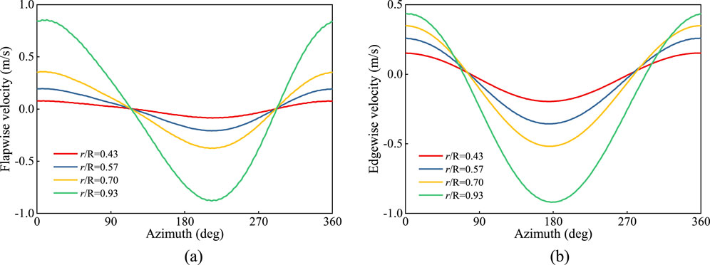
Figure 13. Characteristics of coupling velocity with azimuth angle at different sections under yaw condition. (a) Flapwise velocity. (b) Edgewise velocity.
To further compare the impact of flapwise and edgewise velocities on the amplitude of the angle of attack fluctuations, Figure 14 presents a comparison of the velocity triangle for the blade sections of rigid and flexible blades. On the right, the variation curve of the tangential inflow velocity (i.e., the sum of tangential wind speed and edgewise velocity) with azimuth angle is shown. The results indicate that for the flexible blade, the tangential inflow velocity, resulting from the combination of tangential wind speed and edgewise velocity, is lower than that of the rigid blade, with a reduced fluctuation amplitude. This reduction in fluctuation amplitude is more pronounced in the blade tip region. This suggests that the periodic fluctuations of edgewise velocity reduce the amplitude of the angle of attack fluctuations, rather than increasing it.
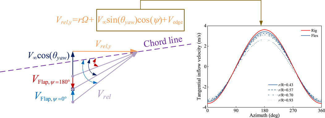
Figure 14. Comparison of velocity triangles for rigid and flexible blades under yaw condition.
However, flapwise velocity increases the fluctuation amplitude of the normal inflow velocity. At 0° azimuth, the flapwise velocity aligns with the normal inflow velocity, causing the angle of attack to increase. At 180° azimuth, the flapwise velocity opposes the normal inflow velocity, causing the angle of attack to decrease. Additionally, under yaw condition, the angle of attack at 0° azimuth is greater than that at 180° azimuth, and the effect of flapwise velocity further exacerbates the difference in the angle of attack between these two azimuth angles. This leads to a significant increase in the amplitude of the angle of attack fluctuations for the flexible blade. Therefore, flapwise velocity is the primary factor responsible for the larger fluctuation amplitude of the aerodynamic load and angle of attack in the flexible blade compared to the rigid blade.
To further investigate the impact of yaw condition and the aeroelastic effects of flexible blades on the load characteristics of a 15 MW wind turbine, this section conducts a comparative analysis at different yaw angles, namely, 10°, 20°, 30°, and 40°. Figure 15 presents the bar chart of the mean amplitude of the wind turbine loads at different yaw angles, including power, thrust, and tilt and yaw moments. As shown in Figures 15A, B, it can be observed that as the yaw angle increases, the mean power of the wind turbine gradually decreases, and the fluctuation amplitude significantly increases. This is due to the fact that as the angle between the wind turbine’s rotating plane and the inflow direction increases, the normal inflow velocity gradually decreases, while the fluctuation amplitude of the tangential inflow velocity continues to increase. This leads to a reduction in the mean relative speed and angle of attack, but an increase in their fluctuation amplitudes. The trend of the mean thrust variation is similar to that of power, showing a decreasing trend. However, the fluctuation amplitude of thrust is relatively smaller than its mean value, and its effect is limited, which can essentially be ignored. Figures 15C, D show that as the yaw angle increases, both the mean and fluctuation amplitudes of the tilt and yaw moments consistently increase. This is mainly because the increasing yaw angle exacerbates the asymmetry of the load distribution between the upper and lower planes, as well as between the left and right planes of the wind turbine.
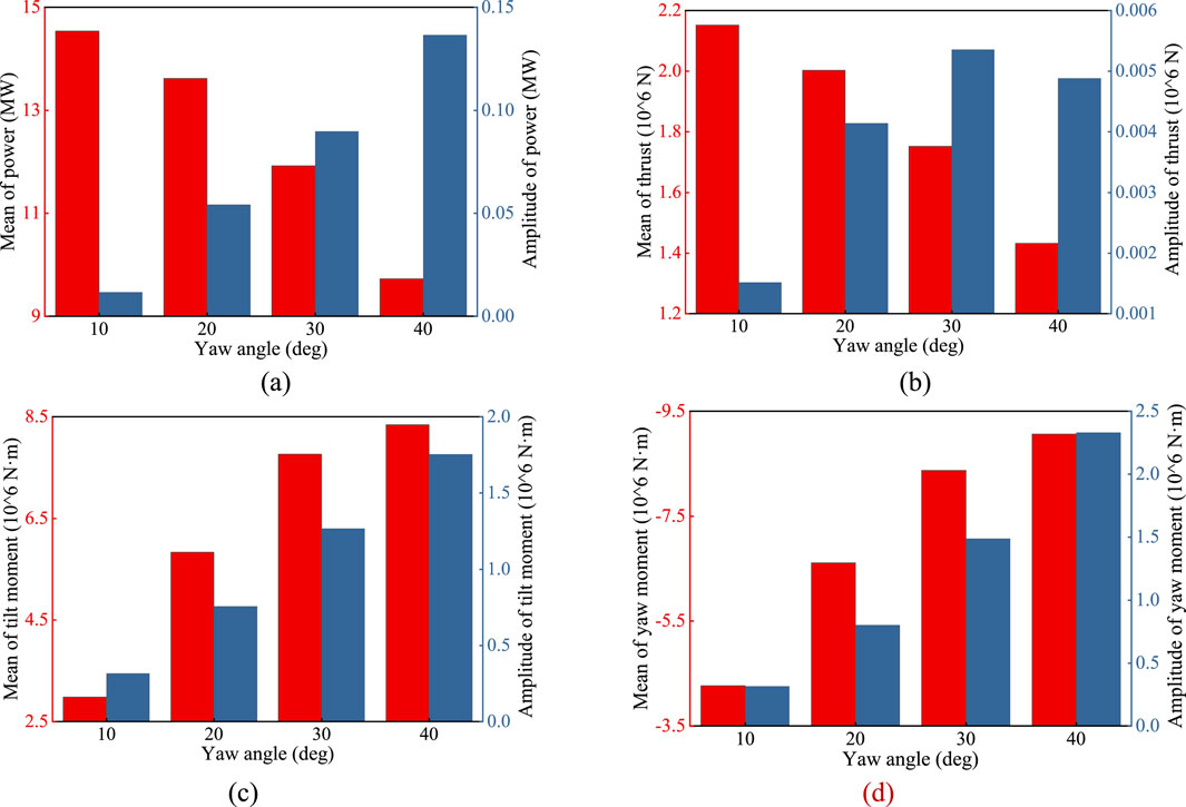
Figure 15. Bar chart of the mean value and amplitude of wind turbine loads at different yaw angles. (a) Power. (b) Thrust. (c) Tilt moment. (d) Yaw moment.
The aerodynamic loads at different yaw angles affect the force characteristics of the blades, which in turn leads to different deflection characteristics. Figure 16 presents the distribution of the deflection amplitude along the spanwise direction of the blade at various yaw angles. It can be observed that as the yaw angle increases, the mean flapwise deflection decreases continuously, while the fluctuation amplitude gradually increases. Notably, at yaw angles of 30° and 40°, the mean flapwise deflection significantly decreases. This indicates that as the yaw angle increases, the mean aerodynamic load on the blade decreases, but the fluctuation amplitude of the load intensifies. Additionally, the mean and fluctuation amplitude of the edgewise deflection decrease as the yaw angle increases. The blade’s torsional deflection, on the other hand, exhibits similar mean values across different yaw angles but shows a gradual increase in fluctuation amplitude as the yaw angle increases.
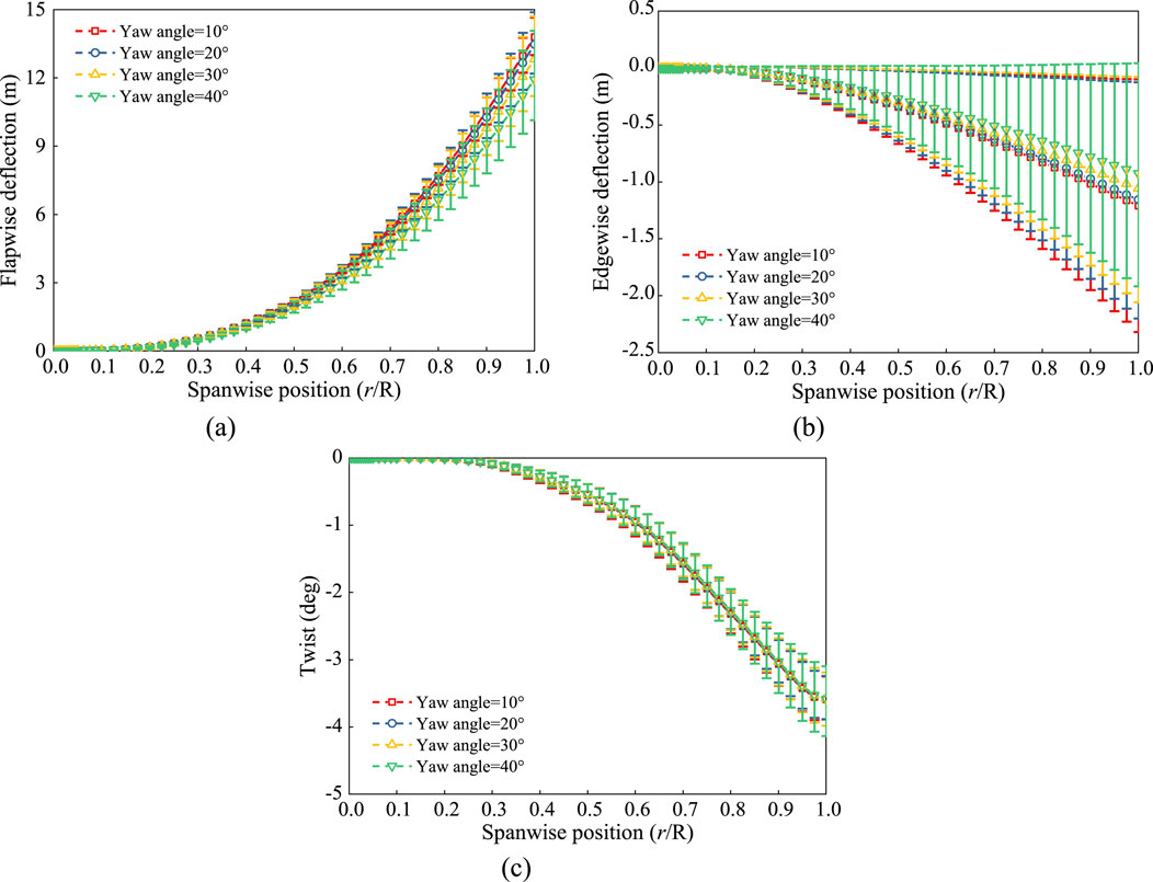
Figure 16. Spanwise amplitude fluctuation of blade deflection at different yaw angles. (a) Flapwise. (b) Edgewise. (c) Tortional.
In the previous analysis, it was found that under yaw condition, the fluctuation amplitude of the angle of attack for flexible blades is larger than for rigid blades, primarily due to the significant periodic fluctuation of the flapwise velocity. To further explore the load characteristics at different yaw angles, Figure 17 shows the spanwise distribution of the blade’s angle of attack and flapwise velocity amplitudes. From Figure 17A, it can be observed that as the yaw angle increases, the mean angle of attack for flexible blades gradually decreases, while the fluctuation amplitude significantly increases. This is because as the yaw angle increases, the normal inflow velocity decreases, leading to a reduction in the angle of attack, while the fluctuation amplitude of the tangential inflow velocity increases, which also exacerbates the fluctuation of the angle of attack. From Figure 17B, it can be observed that the mean flapwise velocity changes little with increasing yaw angle, but its fluctuation amplitude increases significantly. Combining this with the analysis in the previous section, it can be concluded that the increase in flapwise velocity fluctuation amplitude further exacerbates the fluctuation of the angle of attack. Therefore, as the yaw angle increases, the mean angle of attack decreases but its fluctuation amplitude significantly increases, which leads to a reduction in the blade load and wind turbine power mean values, while increasing their fluctuation amplitudes.
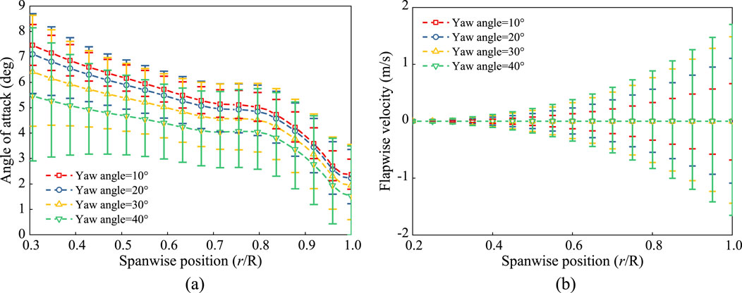
Figure 17. Spanwise amplitude fluctuation of angle of attack and flapping velocity at different yaw angles. (a) Angle of attack. (b) Flapwise velocity.
The inflow environment at different yaw angles affects the shape and evolution characteristics of the wind turbine wake. Figure 18 shows the top view of the wake profile at various yaw angles. As the yaw angle gradually increases, it can be observed that the wake shifts toward the right half-plane of the wind turbine, and the wake structure distorts and changes accordingly. Additionally, as the yaw angle increases, the mean wind turbine load decreases, and the wake profile contracts. At a yaw angle of 10°, the wake structure is relatively regular, and the wake distribution forms a uniform spiral shape, with minimal offset. As the yaw angle increases to 20°, the degree of wake offset increases, and the wake begins to shift more clearly to one side, resulting in a certain amount of distortion in its structure. When the yaw angle further increases to 30° and 40°, the offset phenomenon becomes more pronounced, and the wake structure shows distorted and turbulent characteristics. The distance between wake vortices gradually shortens, and the wake as a whole becomes more compact.
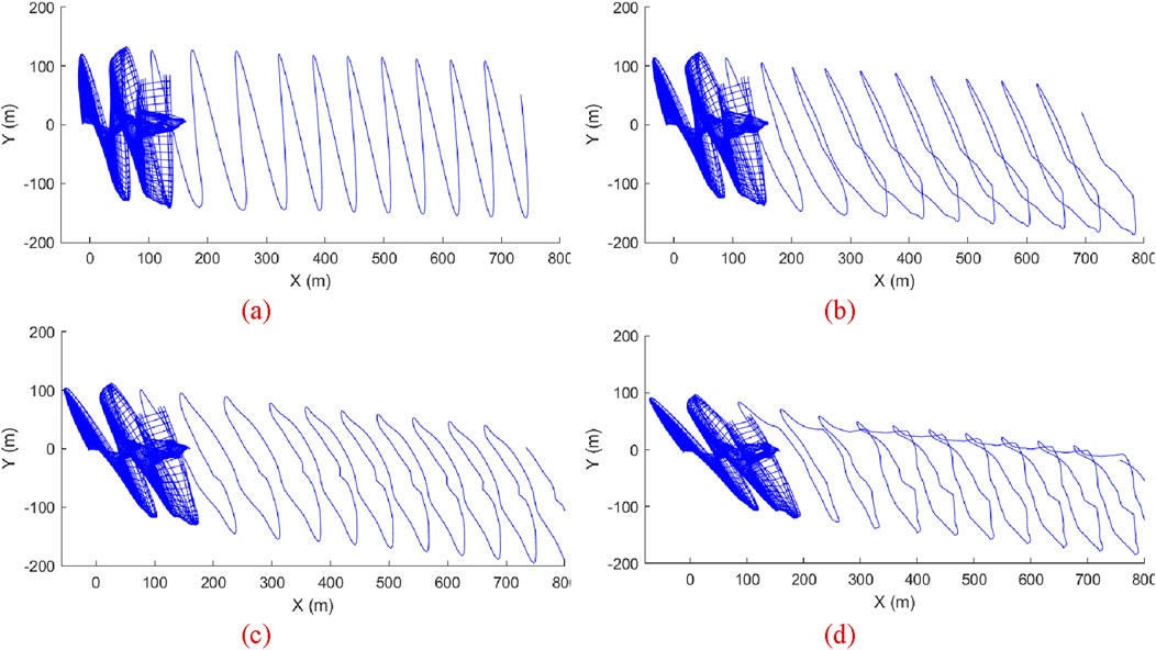
Figure 18. Wake profile of the wind turbine at different yaw angles (top view). (a) 10°. (b) 20°. (c) 30°. (d) 40°.
The present study focuses on the IEA-15 MW wind turbine and investigates the unsteady aeroelastic coupling characteristics under yaw condition based on lifting-line free vortex wake method and geometrically exact beam theory. The following conclusions are obtained.
1) Under yaw condition, the load responses of the wind turbine exhibit obvious fluctuation The mean power and thrust of the flexible-blade wind turbine are lower than those of the rigid-blade wind turbine, while the absolute values of the mean tilt and yaw moments of the flexible-blade wind turbine are higher.
2) The load and angle of attack fluctuations of flexible blades are significant than those of rigid blades. Blade flapwise velocity amplifies the amplitude of angle of attack fluctuations, further increasing the load and power fluctuation amplitudes of the wind turbine. Torsional deflection also intensifies angle of attack fluctuations, though to a lesser extent.
3) After considering blade flexibility, the torsional deflection of the wind turbine blades reduces the effective angle of attack, leading to decreased blade loads. The closer to the blade tip, the more significant the impact of torsional deflection on the angle of attack.
4) As the yaw angle increases, the mean power of the wind turbine gradually decreases while the fluctuation amplitude increases. The mean value and fluctuation amplitudes of tilt and yaw moments increase, and the fluctuation amplitude of flapwise velocity and torsional deflection also grows. This leads to an increasing fluctuation amplitude of angle of attack, while its mean value gradually decreases.
The original contributions presented in the study are included in the article/supplementary material, further inquiries can be directed to the corresponding author.
LM: Project administration, Resources, Writing–review and editing. YL: Methodology, Software, Visualization, Writing–original draft. LZ: Methodology, Software, Writing–review and editing. DY: Project administration, Resources, Writing–review and editing. XS: Project administration, Resources, Supervision, Writing–review and editing. ZD: Supervision, Writing–review and editing.
The author(s) declare that financial support was received for the research and/or publication of this article. The present study is supported by China Three Gorges Corporation (202303058).
The authors thank the editors and reviewers for their comments on this paper.
Authors ML and YD were employed by China Three Gorges Corporation.
The remaining authors declare that the research was conducted in the absence of any commercial or financial relationships that could be construed as a potential conflict of interest.
The authors declare that this study received funding from China Three Gorges Corporation. The funder had the following involvement in the study: Project administration, Resources.
The author(s) declare that no Generative AI was used in the creation of this manuscript.
All claims expressed in this article are solely those of the authors and do not necessarily represent those of their affiliated organizations, or those of the publisher, the editors and the reviewers. Any product that may be evaluated in this article, or claim that may be made by its manufacturer, is not guaranteed or endorsed by the publisher.
Amoretti, T., Huet, F., Garambois, P., and Roucoules, L. (2023). Configurable dual rotor wind turbine model based on BEM method: Co-rotating and counter-rotating comparison. Energy Convers. Manag. 293, 117461. doi:10.1016/j.enconman.2023.117461
Carrión, M., Steijl, R., Woodgate, M., Barakos, G. N., Munduate, X., and Gomez-Iradi, S. (2014). Aeroelastic analysis of wind turbines using a tightly coupled CFD–CSD method. J. Fluids Struct. 50, 392–415. doi:10.1016/j.jfluidstructs.2014.06.029
Chen, J., Shen, X., Zhu, X., and Du, Z. (2019a). Study on composite bend-twist coupled wind turbine blade for passive load mitigation. Compos. Struct. 213, 173–189. doi:10.1016/j.compstruct.2019.01.086
Chen, J., Shen, X., Zhu, X., and Du, Z. (2019b). A study on the capability of backward swept blades to mitigate loads of wind turbines in shear flow. J. ENERGY Resour. TECHNOLOGY-TRANSACTIONS ASME. 141 (8). doi:10.1115/1.4042716
Corniglion, R., Harris, J., Peyrard, C., and Capaldo, M. (2020). Comparison of the free vortex wake and actuator line methods to study the loads of a wind turbine in imposed surge motion. J. Phys. Conf. Ser. 1618 (5), 052045. doi:10.1088/1742-6596/1618/5/052045
Dangi, N., Sodja, J., Ferreira, C. S., and Yu, W. (2025). The effect of turbulent coherent structures in atmospheric flow on wind turbine loads. Renew. Energy 241, 122248. doi:10.1016/j.renene.2024.122248
Duan, L., Sun, Q., He, Z., and Li, G. (2022). Wake topology and energy recovery in floating horizontal-axis wind turbines with harmonic surge motion. Energy 260, 124907. doi:10.1016/j.energy.2022.124907
Fu, S., Li, Z., Zhu, W., Han, X., Liang, X., Yang, H., et al. (2023). Study on aerodynamic performance and wake characteristics of a floating offshore wind turbine under pitch motion. Renew. Energy 205, 317–325. doi:10.1016/j.renene.2023.01.040
Gaertner, E., Rinker, J., Sethuraman, L., Zahle, F., Anderson, B., Barter, G. E., et al. (2020). IEA wind TCP task 37: definition of the IEA 15-megawatt offshore reference wind turbine. Golden, CO (United States): National Renewable Energy Lab.
Ghandour, A., De Troyer, T., and Runacres, M. C. (2022). A combined potential flow–BEM model to study the tower shadow effect in wind turbines. J. Wind Eng. Industrial Aerodynamics 229, 105131. doi:10.1016/j.jweia.2022.105131
Hodges, D. H. (2006). Nonlinear composite beam theory. Reston VA: Reston VA: American Institute of Aeronautics and Astronautics.
Hodges, D. H. (2009). Geometrically exact, intrinsic theory for dynamics of curved and twisted anisotropic beams. AIAA J. 47 (5), 1308–1309. doi:10.2514/1.40556
Kim, K., and Kwon, O. J. (2019). Effect of platform motion on aerodynamic performance and aeroelastic behavior of floating offshore wind turbine blades. Energies 12 (13), 2519. doi:10.3390/en12132519
Leishman, J. G. (2002). Challenges in modelling the unsteady aerodynamics of wind turbines. Wind Energy 5 (2-3), 85–132. doi:10.1002/we.62
Leishman, J. G., and Beddoes, T. S. (1989). A semi-empirical model for dynamic stall. J. Am. Helicopter Soc. 34 (3), 3–17. doi:10.4050/jahs.34.3
Leng, J., Li, G., and Duan, L. (2024). The impact of extreme wind conditions and yaw misalignment on the aeroelastic responses of a parked offshore wind turbine. Ocean. Eng. 313, 119403. doi:10.1016/j.oceaneng.2024.119403
Li, B., Tian, D., Wu, X., Meng, H., and Su, Y. (2023). The impact of bend-twist coupling on structural characteristics and flutter limit of ultra-long flexible wind turbine composite blades. Energies 16 (15), 5829. doi:10.3390/en16155829
Liu, Y., Xiao, Q., Incecik, A., and Peyrard, C. (2019). Aeroelastic analysis of a floating offshore wind turbine in platform-induced surge motion using a fully coupled CFD-MBD method. Wind energy 22 (1), 1–20. doi:10.1002/we.2265
Lu, M.-m., Ke, S.-t., Wu, H.-x., Gao, M.-e., Tian, W.-x., and Wang, H. (2022). A novel forecasting method of flutter critical wind speed for the 15 MW wind turbine blade based on aeroelastic wind tunnel test. J. Wind Eng. Industrial Aerodynamics 230, 105195. doi:10.1016/j.jweia.2022.105195
Özkan, R., and Genç, M. S. (2023). Aerodynamic design and optimization of a small-scale wind turbine blade using a novel artificial bee colony algorithm based on blade element momentum (ABC-BEM) theory. Energy Convers. Manag. 283, 116937. doi:10.1016/j.enconman.2023.116937
Ramos-García, N., González, H. S., Pegalajar-Jurado, A., Kontos, S., and Bredmose, H. (2022). Investigation of the floating IEA wind 15-MW RWT using vortex methods Part II: wake impact on downstream turbines under turbulent inflow. Wind Energy 25 (8), 1434–1463. doi:10.1002/we.2738
Rinker, J., Gaertner, E., Zahle, F., Skrzypiński, W., Abbas, N., Bredmose, H., et al. (2020). Comparison of loads from HAWC2 and OpenFAST for the IEA wind 15 MW reference wind turbine. J. Phys. Conf. Ser. 1618 (5), 052052. doi:10.1088/1742-6596/1618/5/052052
Rodriguez, S. N., and Jaworski, J. W. (2019). Strongly-coupled aeroelastic free-vortex wake framework for floating offshore wind turbine rotors. Part 1: numerical framework. Renew. Energy 141, 1127–1145. doi:10.1016/j.renene.2019.04.019
Sebastian, T., and Lackner, M. A. (2012). Development of a free vortex wake method code for offshore floating wind turbines. Renew. Energy 46, 269–275. doi:10.1016/j.renene.2012.03.033
Shen, X., Chen, J., Hu, P., Zhu, X., and Du, Z. (2018). Study of the unsteady aerodynamics of floating wind turbines. Energy 145, 793–809. doi:10.1016/j.energy.2017.12.100
Shen, X., Chen, J.-G., Zhu, X.-C., Liu, P.-Y., and Du, Z.-H. (2015). Multi-objective optimization of wind turbine blades using lifting surface method. Energy 90, 1111–1121. doi:10.1016/j.energy.2015.06.062
Wang, Q., Yi, X., Liu, Y., Ren, J., Yang, J., and Chen, N. (2024). Numerical investigation of dynamic icing of wind turbine blades under wind shear conditions. Renew. Energy 227, 120495. doi:10.1016/j.renene.2024.120495
Xiao, Y., Wang, X., Sun, X., Zhong, X., Peng, C., Dai, L., et al. (2025). Load reduction and mechanism analysis of cyclic pitch regulation on wind turbine blades under yaw conditions. Ocean. Eng. 321, 120361. doi:10.1016/j.oceaneng.2025.120361
Xu, B., Liu, B., Cai, X., Yuan, Y., and Wang, Y. (2019). Accuracy of the aerodynamic performance of wind turbines using vortex core models in the free vortex wake method. J. Renew. Sustain. Energy 11 (5), 053307. doi:10.1063/1.5121419
Ye, M., Chen, H.-C., and Koop, A. (2024). High-fidelity CFD simulations of two tandemly arrayed wind turbines under various operating conditions. Ocean. Eng. 314, 119703. doi:10.1016/j.oceaneng.2024.119703
Yu, D. O., and Kwon, O. J. (2014). Predicting wind turbine blade loads and aeroelastic response using a coupled CFD–CSD method. Renew. Energy 70, 184–196. doi:10.1016/j.renene.2014.03.033
Zhang, J., Guo, L., Wu, H., Zhou, A., Hu, D., and Ren, J. (2014). The influence of wind shear on vibration of geometrically nonlinear wind turbine blade under fluid–structure interaction. Ocean. Eng. 84, 14–19. doi:10.1016/j.oceaneng.2014.03.017
Zhang, Y., Song, C., and Li, Z. (2022). Influence of wind turbine structural parameters on wind shear and tower shadow effect. Energy Eng. 120 (2), 501–510. doi:10.32604/ee.2022.021423
Keywords: aeroelastic performance, yaw condition, free vortex wake method, geometrically exact beam theory, blade deflection
Citation: Ma L, Li Y, Zhou L, Yang D, Shen X and Du Z (2025) Study on the aeroelastic performance of 15 MW wind turbine under yaw condition. Front. Energy Res. 13:1571567. doi: 10.3389/fenrg.2025.1571567
Received: 05 February 2025; Accepted: 12 March 2025;
Published: 24 March 2025.
Edited by:
Wen Zhong Shen, Yangzhou University, ChinaCopyright © 2025 Ma, Li, Zhou, Yang, Shen and Du. This is an open-access article distributed under the terms of the Creative Commons Attribution License (CC BY). The use, distribution or reproduction in other forums is permitted, provided the original author(s) and the copyright owner(s) are credited and that the original publication in this journal is cited, in accordance with accepted academic practice. No use, distribution or reproduction is permitted which does not comply with these terms.
*Correspondence: Xin Shen, c2hlbnhpbkBzanR1LmVkdS5jbg==
Disclaimer: All claims expressed in this article are solely those of the authors and do not necessarily represent those of their affiliated organizations, or those of the publisher, the editors and the reviewers. Any product that may be evaluated in this article or claim that may be made by its manufacturer is not guaranteed or endorsed by the publisher.
Research integrity at Frontiers
Learn more about the work of our research integrity team to safeguard the quality of each article we publish.