 Shangke Liu1
- 1State Grid Ningxia Electric Power Co., Ltd Eco-tech Research Institute, Ningxia, China
- 2Beijing DC T&D Engineering Technology Research Center (NARI China-EPRI Electrical Engineering Co., Ltd.), Beijing, China
The grid-forming control (GFM) is treated as controlled voltage sources, which can enhance synchronize stability in weak grid case. However, the dynamic response of existing GFM method is limited, and the transient overcurrent in fault is still not solved well, which limits its wide application in distribution network. Drawing from a DC transformation project in an electroplating industrial park in China, this paper proposes an improved GFM control strategy for medium-voltage megawatt converters. The proposal includes the following: firstly, this paper presents an overview of GFM/GFL converters control method; secondly, the establishment of a mathematical model for MMC converters; thirdly, the development of a new MMC grid-forming control technology based on model predictive control, for achieving improved current limitation, dynamic response, and power quality, finally, the verification of these concepts through simulations. This paper provides new insights and strategies for Megawatt-level converter, and reducing carbon emissions in DC industrial parks.
1 Introduction
The distribution network is increasingly populated by DC industrial loads, such as those from the electroplating industry, data centers, and energy storage systems, contributing to a significant rise in carbon emissions and environmental pollution. For instance, an electroplating industrial park in Pingyang County, Zhejiang Province, China, has an average annual load of 5 MW, with annual electricity consumption exceeding 100 million kilowatt-hours, 70% of which is DC load. This high energy consumption is accompanied by stringent power quality demands. A critical challenge, therefore, is how to reduce carbon emissions in DC industrial parks, particularly electroplating facilities, through the integration of new energy sources. In 2023, a demonstration project to transform the medium-voltage DC power supply was implemented at Pingyang Electroplating Industrial Park in China. This project utilized two small-capacity VSC converters for ±10 kV DC energy conversion, leading to significant reductions in energy consumption. However, as the power grid’s carbon reduction requirements become more stringent, there is a need to incorporate larger distributed photovoltaic and energy storage systems. Modular multilevel converter (MMC) technology offers a significant advantage over the C-NPC topology by easily increasing the output voltage and capacity of a single converter. This makes it particularly suitable for applications involving large-scale distributed photovoltaic systems and DC industrial parks. The power supply scheme for a medium-voltage DC electroplating industrial park is shown in Figure 1.
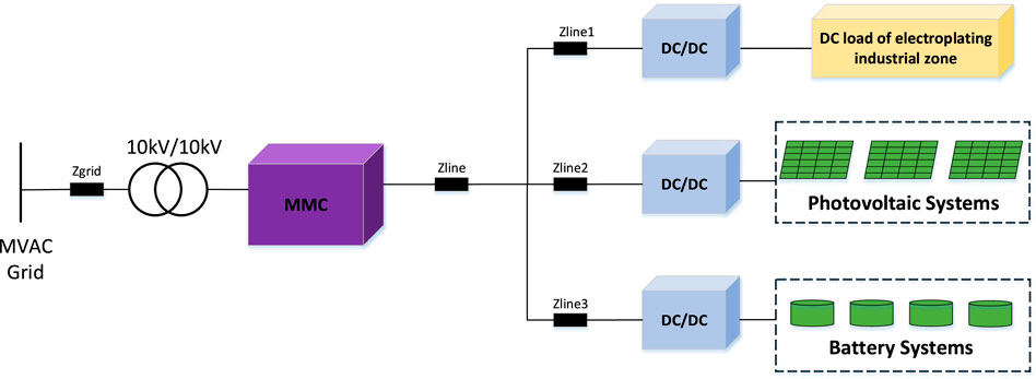
Figure 1. Power supply scheme of medium voltage DC electroplating industrial park based on MMC.
MMC technology is widely utilized in renewable energy, energy storage systems, and HVDC transmission due to its high efficiency. The MMC converters are typically controlled as current sources, which follow the frequency and phase of the grid by phase-locked loops (Pan et al., 2017; Du et al., 2021). This grid synchronization control is known as grid-following control (GFL). The GFL mode based on phase-locked loop control can ensure system stability and power control rapidity under a strong grid, which has many limitations in terms of stability, system voltage, and frequency adjustment, and adapting to a scenario where a high proportion of renewable energy generation units are connected is difficult. When connected to weak grid, the synchronizationz dynamics of GFL converters is more susceptible to perturbation and then instability (Wang et al., 2018; Hu et al., 2019; Hu et al., 2021).
GFM converters reproduce the behavior of a voltage source behind an impedance, and contributing to the strength of weak power grid by regulating voltage and frequency. Gao et al. (2017) presents an adaptive virtual frequency modulation control strategy that dynamically adjusts the inertia coefficient to improve frequency stability. Zhao et al. (2022) provides a detailed analysis of the virtual synchronous generator’s parameter design, focusing on stability and dynamic performance, and outlines the principles for parameter setting. Several GFM control methods are proposed in the literature (Zhong et al., 2014; Rodriguez et al., 2018; Zhang et al., 2010; Matevosyan et al., 2019), comparisons between GFL and GFM converters illustrated in Table 1.
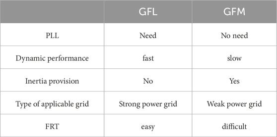
Table 1. Comparison between GFL and GFM converters.
Due to the voltage source behavior of the GFM converters in contrast to GFL converters, the overcurrent protection requires particular attention. Therefore, various current-limiting threshold control methods for GFM convertersare reported in the literature, including current threshold limiters, virtual impedance, virtual admittance.
To control the output current of GFM inverter during faults, paper (Bottrell and Green, 2014) restricts the phase current magnitude with the maximum allowed value through closed-loop current control, authors in (Pirsto et al., 2022) have proposed a state feedback control based cascaded voltage and current loop. When the converter is overloaded, the controller shifts to the current control mode (CCM) from the voltage control mode (VCM) to control the output current. Since the references generated by the voltage controller are unutilized, the voltage source behaviour of the GFM is lost. Also, this necessitates using an anti-windup control for the voltage controller, leading to delays in the recovery period. The current limiting control performance of GFM converters with and without transitioning to GFL with varying grid strengths is compared in (Taul et al., 2020). The comparison have shown that when GFL performed satisfactorily with strong grids, it might lead to unstable behaviour in weak grids because of the stability issues associated with phase locked loop (PLL).
GFM based on virtual impedance control with aim to adjusts the impedance
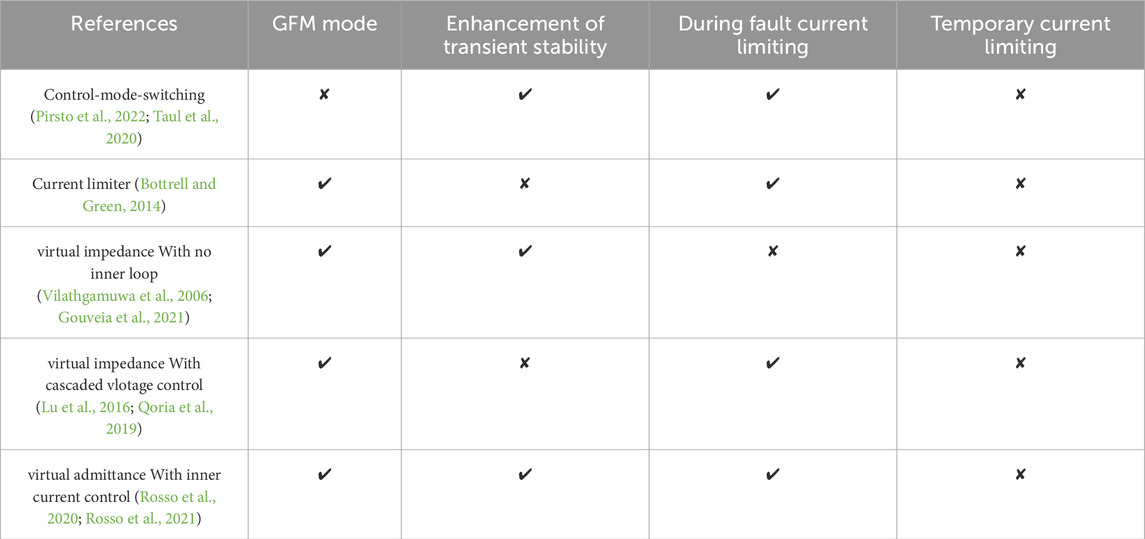
Table 2. Comparisons of existing current-limiting control methods.
Conventionally, a cascaded dual-loop linear feedback control is deployed in the inner loop of GFM. However, this control scheme PI parameter setting is complex, suffers from a slow transient response, limited control bandwidth, and instantaneous current overlimits. Moreover, it is hard for a linear controller to handle the multi-objective optimization and various system constraints, for example, MMC (Vazquez et al., 2017).
A improved GFM strategy based virtual admittance combined with direct modulation MPC method is proposed in this work. The improved control strategy has simplified structure, fast dynamic response speed and strong current limiting ability.
The main contributions of the work are:
(i) The proposed scheme combines an virtual admittance reference current and currentlimit objective into the MPC cost functions, which enhanced fault ride-through of GFM-MMC converter.
(ii) Without any transient overcurrents and overvoltagees during fault initiation or recovery after fault clear, compared with PI control strategy, MPC method can provide faster active power recovery.
(iii) Verified that the proposed control strategy can run stably under wide SCR, the power quality and dynamic response speed are better than the PI control.
In the parts to follow: Section 2 details the establishment of a mathematical model for MMC converters. The controller design for the MPC-VSG MMC are discussed in Section 3. Section 4 shows verification of these concepts through simulations include current limitation, dynamic response, and power quality. Finally conclusions of the work are summarised in Section 5.
2 Mathematical model of grid-connect MMC
The MMC consists of a three-phase structure with six bridge arms, where each bridge arm has an inductance Larm, and resistance Rarm, with N half-bridge submodules connected in series. The topology of the MMC is illustrated in Figure 2.
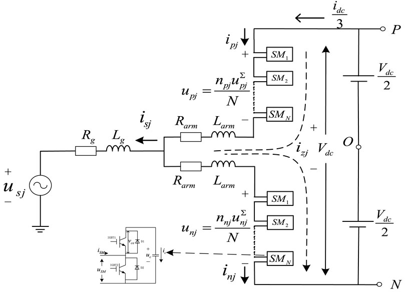
Figure 2. Topology of grid-connect MMC.
As shown in Figure 2,
Add and subtract Equation 1 and Equation 2, respectively.
where,
where
By Equations 3, 4, the unbalanced current inside MMC
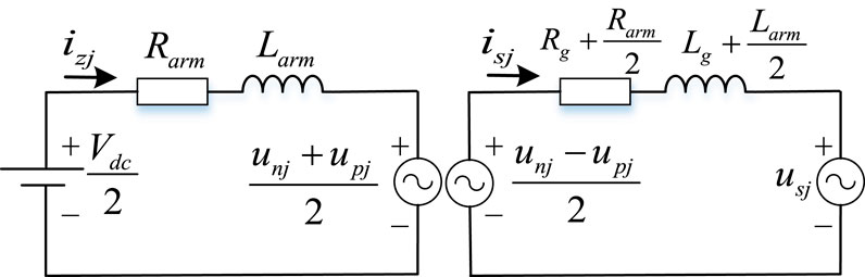
Figure 3. MMC AC and DC equivalent circuit.
3 MMC grid-forming control method based on model predictive control
3.1 MMC traditional double closed loop PI control
The MMC typically employs a double-closed-loop PI control, as shown in Figure 4. Pref, Vdcref, Qref, Usmref, idref, iqref, uabcref are the references of active power, reactive power, DC voltage and the PCC AC voltage, d-axis current, q-axis current, modulation of arm voltage, respectively; and P, Q, Vdc, Usm, isabc, usd, usq, ωref, are the output active power, reactive power, DC voltage, PCC AC voltage, PCC AC current, d-axis voltage, q-axis voltage, angular frequency, respectively; kp1, ki1, kp2, ki2, are out-loop and inner-loop proportional and integral coefficients.
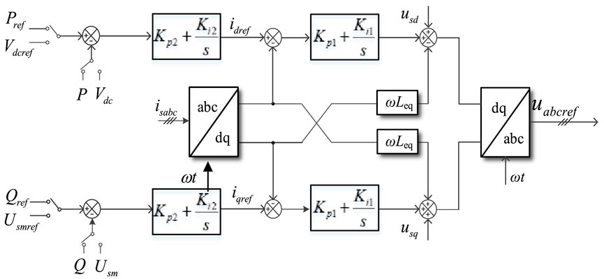
Figure 4. Traditional PI double closed loop control.
The powers are calculated in the dq-frame as:
In the dq reference frame, (Equation 9) expressed as:
Req and Leq in (Equation 10) are expressed in
In (Equation 10) expressed Laplace domain as:
Transfer functions for output variables isd, isq and voltages Vd and Vq expressed as:
Where
By Equations 11, 12, the input-output relationship (Figure 5) of d-axis current, q-axis current expressed as:

Figure 5. The input-output relationship of d-q current.
According to the negative feedback theory, the current reference value idref and iqref can be well tracked by PI control, similarly the active power and reactive power can be well tracked and controlled.
3.2 Grid-forming virtual synchronization control
Traditional MMC double-PI control typically uses fixed reference values for its targets, making it incapable of actively adjusting to variations in grid voltage and frequency. The core concept of grid-forming control is to modify the converter control mode, enabling it to exhibit rotational inertia and autonomously provide active or reactive power support to the grid. The mathematical equations governing the grid-forming virtual synchronous generator (VSG) control for the MMC are presented as follows.
Equations 13–15 describe the rotor motion equation, the reactive power-voltage control equation, and the electrical equation of the VSG body used for virtual synchronous control.
In these equations, P* and P are the reference power and actual active power, respectively. J and Dp are the VSG control parameters refer to virtual rotational inertia and damping coefficient respectively, ω0and ω refer to the rated velocity and actual electrical angular velocity, respectively, Q* and Q are the reference power and actual active power, respectively. En is the no-load electromotive force in the synchronous generator. Rv and Lv are the virtual resistance and inductance of VSG, respectively. ijref is the three-phase current reference value of VSG output. ejref is the internal potential reference value. uj is the three-phase voltage of the MMC grid connection point.
The control block diagram for the VSG in the MMC is shown in Figure 6. The stator voltage is determined using P-f control and Q-V control, with virtual impedance Rv and Lv incorporated into the electrical section of the VSG model. The current command value ijref, which satisfies the stator voltage equation, is computed through the virtual impedance loop. The d-q current references, idref and iqref, are then used as inputs to the current inner loop in Figure 4, completing the simulation of the stator voltage equation in VSG control.
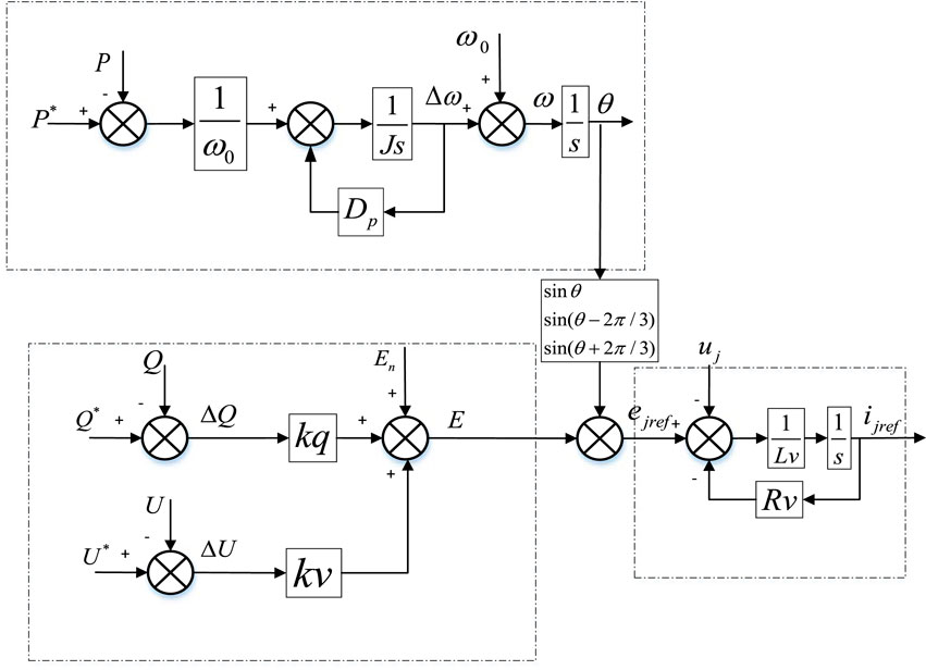
Figure 6. Virtual synchronous control block diagram.
By adjusting the values of J and Dp, different active power response characteristics of the MMC can be achieved. The dynamic response of the output power for the MMC, with different J and Dp coefficients, under VSG control is shown in Figures 7, 8.
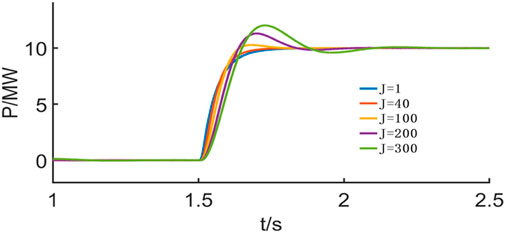
Figure 7. Dynamic response of different J.
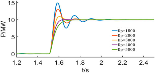
Figure 8. Dynamic response of different Dp.
As illustrated in Figures 7, 8, increasing the virtual inertia J results in a larger amplitude and a longer response time to the P/Q reference signals. Conversely, increasing the virtual damping coefficient Dp leads to a smaller amplitude and a shorter response time. In practice, Dp is generally determined by grid standards, and the dynamic performance of the MMC is primarily adjusted by modifying J.
3.3 Grid-forming based on model predictive control
Model predictive control (MPC) is an advanced control method for power electronics, based on predicting the next AC grid-side current by establishing a discrete mathematical model of the converter. It then performs a traversal calculation of all possible switching states of the power electronics, ultimately achieving optimal control within each control period.
Unlike traditional control methods, MPC does not rely on a PI control loop, making it structurally simpler, requiring no complex parameter tuning. MPC offers fast tracking responses, minimal overshoot, and superior dynamic performance (Zheng, 2020). In this paper, MPC is applied to the virtual synchronous control of the MMC, and a corresponding cost function is designed to address circulating currents and DC voltage fluctuations, as illustrated in Figure 9.
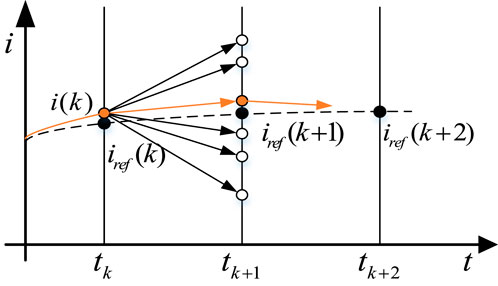
Figure 9. Basic principles of model predictive control.
The power control outer loop of grid-forming control is implemented as MPC-VSG, where the traditional PI current loop is replaced by the MPC model predictive controller. In this setup, the current reference ijref of the VSG output (as shown in Figure 6) serves as the input reference for the model predictive control. The discrete mathematical Equations 7, 8, of the MMC are combined to construct the cost function for MPC.
Depending on disturbances in the AC grid frequency or voltage, or input changes in the active power command (Pref or Vdc) or reactive power command (Qref or Usm), the three-phase current reference isjref (t + Ts) (j = a, b, c) is calculated using Equations 13–15.
The first cost function of MPC-VSG is built.
Combined with (Equation 7), the upper and lower bridge arms voltage difference value
Equation 8 highlights the presence of circulating currents within the MMC, which, while circulating only inside the MMC, do not affect the external AC or DC sides. However, these currents contribute to increased power device losses and must be suppressed. In this work, we address this issue by controlling the circulating currents through adjustments to the additional voltage
The second cost function of MPC-VSG is obtained.
where
The lower number under the MPC-VSG control strategy is obtained.
Submodule voltage balancing is achieved using the nearest-level approximation method. By combining Equations 20, 21, the submodule sequence for each arm is determined, and the corresponding control pulses are applied to the MMC.
Three control objectives are incorporated into the proposed Level MPC these are AC current, circulating current, and strict fault current limit. control objectives are achieved through the cost function
Within the cost function,
3.4 Threshold current controller design of grid-forming
To mitigate transient overcurrents, the proposed method limits the amplitude of the reference current under the d-q framework while maintaining the current phase. This ensures that power supply quality is preserved during fault conditions to the greatest extent possible. The strategy is described as follows:
where
The basic principles of model predictive control refer to Figure 10.

Figure 10. Basic principles of model predictive control.
4 Simulation verification
To validate the proposed grid-forming control strategy, a grid-forming MMC system was built and tested in Simulink. For the purpose of analysis and comparison, the DC side of the grid-connected MMC is connected to a constant DC voltage source, while the AC side uses a three-phase programmable voltage source to simulate frequency and voltage fluctuations. The system simulation parameters are provided in Table 3.
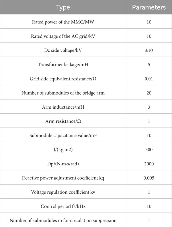
Table 3. Simulation parameters.
4.1 Simulation of dynamic characteristics of MMC
The active power step simulation of the MMC converter is conducted under a grid-forming control strategy. The simulation parameters for the MMC converter and system are provided in Table 3. The number of submodules, denoted as “m,” used to suppress circulating current is set to 1. The time-domain simulation results are presented in Figure 11. Before t = 3 s, MMC operates statically at −5 MW, with a circulating current of approximately 20 A. At t = 3 s, the active power jumps to 5 MW, with the circulating current remaining around 20 A. During this transition, the capacitor voltage fluctuates by about 6% due to the circulating current. The MMC converter operates stably throughout the step process, fulfilling the specification requirements.
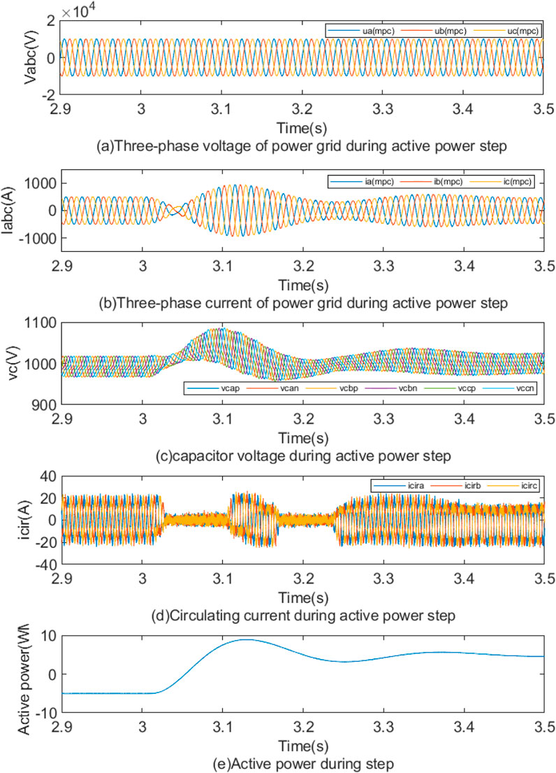
Figure 11. (A) Three-phase voltage of power grid during active power step. (B) Three-phase current of power grid during active power step. (C) capacitor voltage during active power step. (D) Circulating current during active power step. (E) Active power during step.
To fully compare the dynamic response characteristics of the inertia support with the proposed control strategy, the simulation experiment under sudden change of load is carried out. During normal operation, the synchronous generator is 20 MVA, the load is 20 MW, and MMC-HVDC provided 5 MW power to the load. At 3 s, the 7 MW load is suddenly put into, with the frequency transient response characteristics under the two controls observed. As shown in Figure 12, at t = 3 s, based on PI-VSG control, the grid frequency f drops to 49.25 Hz. However, based on MPC-VSG control, the frequency occurs 49.29 Hz, which reduced by 0.04 Hz.
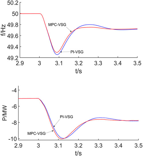
Figure 12. Frequency dynamic response under sudden change of load.
When the system frequency decreases, both strategies can achieve the rapid response adjustment of active power. Compared with PI-VSG control, MMC under MPC-VSG control has a faster power tracking speed.
4.2 Grid-forming MMC transient characteristics under grid faults
4.2.1 Effects of different inertia coefficients J and SCR on transient stability
A three-phase short-circuit fault is simulated in the power grid, with the fault location at the converter outlet and a fault resistance of 0.01 Ω. The fault occurs at t = 3 s and lasts for 60 m, with a system short-circuit ratio (SCR) of 3. The reference value for the inertia coefficient J is set to 300. The transient fault characteristics are examined for inertia coefficients of 0.3, 0.5, and 1.0 p.u.
Figure 13 illustrates the transient fault characteristics of grid-forming MMC converters under different inertia coefficients J during grid faults. Figure 10A shows the phase portraits of MMC converters during the fault process. It is evident that a smaller inertia coefficient
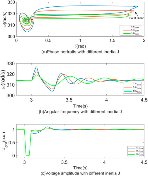
Figure 13. Effects of different inertia coefficients J on transient stability.
Figure 14 illustrates the transient fault characteristics of grid-forming MMC converters under different SCR during grid faults. The result shows that when increasing the grid SCR, the power angle
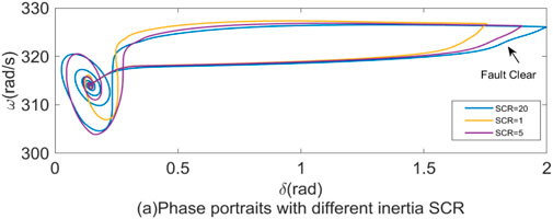
Figure 14. Effects of different SCR on transient stability.
4.2.2 Comparison of MPC and PI with grid-forming strategy under grid faults
The fault simulation conditions are consistent with those outlined in Section 4.2.1, with the fault current limited to 1.5 p.u. Figure 15 presents the phase diagram and fault current limiting waveform for grid-forming MMC converters under both MPC and PI control strategies. Upon fault clearing, the power angle and active power under the MPC strategy recover to their pre-fault conditions more rapidly than under the PI strategy. As shown in Figure 11C, the grid voltage increases less during fault recovery with the MPC strategy. Furthermore, Figure 11D clearly illustrates that under the PI strategy, the C-phase current reaches 2 kA (2 p.u.), while the current in all three phases under the MPC strategy remains within the threshold.
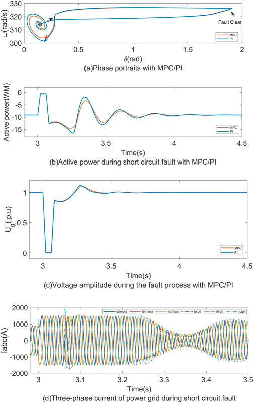
Figure 15. Comparison of MPC and PI according to the grid-forming strategy under grid faults.
4.2.3 Power quality assessment
To evaluate the power quality of the output voltage and current under the proposed strategy, the fault simulation conditions are kept consistent with those described in Section 4.2.1, with a fault current limit of 1.5 p. u. and a fault resistance of 0.5 Ω.
The proposed control strategy is compared with the PI strategy and the MPC current limiting strategy from reference (Zheng, 2020). The voltage and current waveforms are shown in Figure 16, and the THD of both voltage and current under the three strategies are compared in Figure 17. As seen in Figures 16E, F, 17E, F, the proposed control strategy maintains excellent power quality during both steady-state and fault conditions, with voltage and current THD of 2.73% and 2.52%, respectively, and accurately limits the current below 1.5 p. u. In contrast, under the PI strategy, current overruns are observed during the fault, with voltage and current THD of 5.65% and 4.19%, respectively. Under the MPC current limiting strategy from reference (Zheng, 2020), the current is strictly limited to less than 1.5 p.u., but the waveform is clipped, resulting in poor power quality with voltage and current THD of 39.59% and 31.93%, respectively.
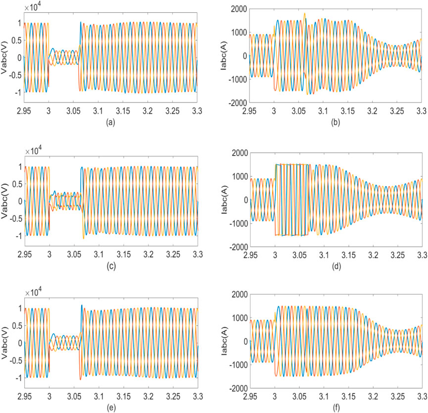
Figure 16. Three-phase voltage and current in (A, B) the PI-based strategy, (C, D) the MPC-based strategy in (Matevosyan et al., 2019), and (E, F) the proposed MPC strategy.
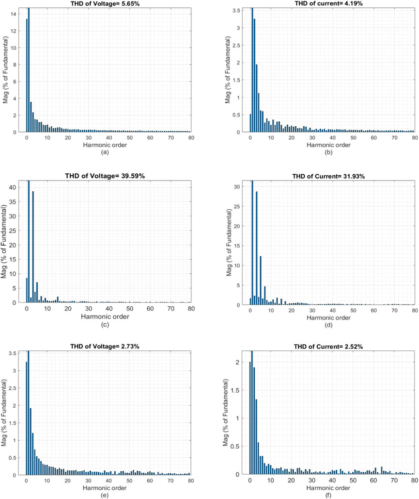
Figure 17. THD of voltage and current in (A, B) the PI-based strategy, (C, D) the MPC-based strategy in (Matevosyan et al., 2019), and (E, F) the proposed MPC strategy.
5 Conclusion
Grid forming converters have become attracrive candidates in the high penetration of distributed energy resources grid. This paper first compared existing GFL and GFM strategies, a improved GFM-MMC strategy based virtual admittance combined with direct modulation MPC method is proposed, which obtained faster and strict current-limiting capability, improved dynamic response, and power quality. Finally, the verification of these concepts through simulations. This strategy aims to enhance the stability of the power supply system and improve the fault tolerance of the grid, offering a novel approach to carbon emission reduction in DC industrial parks.
Data availability statement
The original contributions presented in the study are included in the article/supplementary material, further inquiries can be directed to the corresponding author.
Author contributions
SL: Methodology, Writing–review and editing. XD: Conceptualization, Methodology, Writing–review and editing. YX: Supervision, Writing–review and editing. YL: Conceptualization, Writing–review and editing. RZ: Supervision, Writing–review and editing.
Funding
The author(s) declare that financial support was received for the research, authorship, and/or publication of this article. This research was funded by State Grid Ningxia Electric Power Company Technology Project Support (5229JY22000H) and Ningxia Natural Science Foundation (2023A1155). The funder was not involved in the study design, collection, analysis, interpretation of data, the writing of this article, or the decision to submit it for publication.
Conflict of interest
Authors SL, YX, YL, and RZ were employed by State Grid Ningxia Electric Power Co., Ltd Econ-tech Research Institute. Author XD was employed by Beijing DC T&D Engineering Technology Research Center (NARI China-EPRI Electrical Engineering Co., Ltd.).
Generative AI statement
The author(s) declare that no Generative AI was used in the creation of this manuscript.
Publisher’s note
All claims expressed in this article are solely those of the authors and do not necessarily represent those of their affiliated organizations, or those of the publisher, the editors and the reviewers. Any product that may be evaluated in this article, or claim that may be made by its manufacturer, is not guaranteed or endorsed by the publisher.
References
Bottrell, N., and Green, T. C. (2014). Comparison of current-limiting strategies during fault ride-through of convertersto prevent latch-up and wind-up. IEEE Trans. Power Electron. 29 (7), 3786–3797. doi:10.1109/TPEL.2013.2279162
Du, W., Tuffner, F. K., Schneider, K. P., Lasseter, R. H., Xie, J., Chen, Z., et al. (2021). Modeling of grid-forming and grid-following convertersfor dynamic simulation of large-scale distribution systems. IEEE Trans. Power Delivery 36 (4), 2035–2045. doi:10.1109/TPWRD.2020.3018647
Gao, B., Xia, C., and Zhang, L. (2017). Modeling and parameters design for rectifier side of VSC-HVDC based on virtual synchronous machine technology. Proc. CSEE 37 (2), 534–544. doi:10.13334/j.0258-8013.pcsee.161644
Gouveia, J., Moreira, C., and Lopes, J. P. (2021). Rule-based adaptive control strategy for grid-forming inverters in islanded power systems for improving frequency stability. Power Syst. Res. 197, 107339. doi:10.1016/j.epsr.2021.107339
Hu, Q., Fu, L., Ma, F., and Ji, F. (2019). Large signal synchronizing instability of PLL-based VSC connected to weak AC grid. IEEE Trans. Power Syst. 34 (4), 3220–3229. doi:10.1109/TPWRS.2019.2892224
Hu, Q., Fu, L., Ma, F., Ji, F., and Zhang, Y. (2021). Analogized synchronous generator model of PLL-based VSC and transient synchronizing stability of converter dominated power system. IEEE Trans. Sustain. Energy 12 (2), 1174–1185. doi:10.1109/TSTE.2020.3037155
Huang, L., Wu, C., Zhou, D., and Blaabjerg, F. (2021). Impact of virtual admittance on small-signal stability of grid-forming inverters. in Proc. in IEEE 6th workshop electron. grid (eGRID), 1–8. doi:10.1109/eGRID52793.2021.9662150
Lu, X., Wang, J., Guerrero, J. M., and Zhao, D. (2016). Virtual-impedance based fault current limiters for inverter dominated AC microgrids. IEEE Transactions on Smart Grid. 9 (3), 1599–1612. doi:10.1109/TSG
Matevosyan, J., Badrzadeh, B., Prevost, T., Quitmann, E., Ramasubramanian, D., and Urdal, H. (2019). Grid-forming inverters: are they the key for high renewable penetration? IEEE Power Energy Magazine 17 (6), 89–98. doi:10.1109/MPAE.2023.10083082
Pan, D., Ruan, X., Wang, X., Yu, H., and Xing, Z. (2017). Analysis and design of current control schemes for LCL-type grid-connected inverter based on a general mathematical model. Power Electron. 32 (6), 4395–4410. doi:10.1109/tpel.2016.2602219
Pirsto, V., Kukkola, J., and Hinkkanen, M. (2022). Multifunctional cascade control of voltage-source converters EquippedWith an LC filter. IEEE Trans. Ind. Electron. 69 (3), 2610–2620. doi:10.1109/TIE.2021.3065602
Qoria, T., Gruson, F., Colas, F., Denis, G., Prevost, T., and Guillaud, X. (2019). Critical clearing time determination and enhancement of grid-forming converters embedding virtual impedance as current limitation algorithm. Emerg. Sel. Top. Power Electron. 8 (2), 1050–1061. doi:10.1109/jestpe.2019.2959085
Rodriguez, P., Citro, C., Candela, I., Rocabert, J., and Luna, A. (2018). Flexible grid connection and islanding of SPC-based PV power converters. IEEE Trans. Ind. App. 54 (3), 2690–2702. doi:10.1109/TIA.2018.2800683
Rosso, R., Engelken, S., and Liserre, M. (2020). Current limitation strategy for grid-forming converters under symmetrical and asymmetrical grid faults. in Proc. IEEE Energy Convers. Congr. Expo., 3746–3753. doi:10.1109/ECCE44975.2020.9236314
Rosso, R., Engelken, S., and Liserre, M. (2021). On the implementation of an FRT strategy for grid-forming converters under symmetrical and asymmetrical grid faults. IEEE Trans. Ind. App. 57 (5), 4385–4397. doi:10.1109/TIA.2021.3095025
Taul, M. G., Wang, X., Davari, P., and Blaabjerg, F. (2020). Current limiting control with enhanced dynamics of grid-forming converters during fault conditions. Emerg. Sel. Top. Power Electron. 8 (2), 1062–1073. doi:10.1109/jestpe.2019.2931477
Vazquez, J., Rodriguez, M., Rivera, L. G., and Franquelo, M. (2017). Model predictive control for power converters and drives: advances and trends. IEEE Trans. Ind. Electron. 64 (2), 935–947. doi:10.1109/TIE.2016.2625238
Vilathgamuwa, D. M., Loh, P. C., and Li, Y. (2006). Protection of microgrids during utility voltage sags. IEEE Trans. Ind. Electron. 53 (5), 1427–1436. doi:10.1109/TIE.2006.882006
Wang, X., Harnefors, L., and Blaabjerg, F. (2018). Unified impedance model of grid-connected voltage-source converters. IEEE Trans. Power Electron. 33 (2), 1775–1787. doi:10.1109/TPEL.2017.2684906
Zhang, L., Harnefors, L., and Nee, H. P. (2010). Power synchronization control of grid-connected voltage source converters. IEEE Trans. Power Electron. 25 (2), 809–820. doi:10.1109/TPWRS.2009.2032231
Zhao, B., Zhao, B., and Liang, H. (2022). Overview of grid forming converter technology. J. Beijing Info. Sci. Tech. Univ. 37(4), 57–65. doi:10.16508/j.cnki.11-5866/n.2022.04.010
Zheng, C. (2020). Model predictive control based virtual inertia emulator for an islanded alternating current microgrid. IEEE Trans. Ind. Electron. 68 (8), 7167–7177. doi:10.1109/TIE.2020.3007105
Keywords: DC industrial park, MW-level converter, grid-forming control, model predictive control, carbon reduction, distribution network
Citation: Liu S, Du X, Xiao Y, Liu Y and Zhao R (2025) Megawatt-level converter grid-forming control technology by adopting MPC for medium voltage distribution network. Front. Energy Res. 13:1536987. doi: 10.3389/fenrg.2025.1536987
Received: 29 November 2024; Accepted: 10 February 2025;
Published: 05 March 2025.
Edited by:
Wenping Zhang, Tianjin University, ChinaCopyright © 2025 Liu, Du, Xiao, Liu and Zhao. This is an open-access article distributed under the terms of the Creative Commons Attribution License (CC BY). The use, distribution or reproduction in other forums is permitted, provided the original author(s) and the copyright owner(s) are credited and that the original publication in this journal is cited, in accordance with accepted academic practice. No use, distribution or reproduction is permitted which does not comply with these terms.
*Correspondence: Xiangnan Du, jaydxn@163.com