 Yifu Lin
 Junwei Zhu2
94% of researchers rate our articles as excellent or good
Learn more about the work of our research integrity team to safeguard the quality of each article we publish.
Find out more
ORIGINAL RESEARCH article
Front. Energy Res., 24 March 2025
Sec. Smart Grids
Volume 13 - 2025 | https://doi.org/10.3389/fenrg.2025.1526992
This article is part of the Research TopicAdvances in Renewable Energy System Monitoring, Situational Awareness, and ControlView all 22 articles
Conventional model-based predictive voltage control (MBPVC) for grid-forming inverters (GFIs) in renewable energy system is sensitive to parametric accuracy. To address this issue, an improved model-free predictive voltage control (MFPVC) is proposed for grid-forming inverter. First, the parametric impact on MBPVC is analyzed in GFI. Then, the adaptive ultra-local data-model (ULDM) of the GFI is established for model-free voltage prediction. The ULDM of GFI is updated in each control period by combining the capacitor voltage gradient relationship. The linear extended-state-observer with the adaptive strengthening factor is designed to enhance the performance of the ULDM. Additionally, the optimal switching sequence is proposed for further reducing voltage ripples. The duration of each voltage vector in corresponding optimal switching sequence is calculated based on the deadbeat principle. The proposed MFPVC method effectively eliminates parametric effect and improve the accuracy of model-free voltage prediction. Finally, the conventional MBPVC, conventional MFPVC and proposed MFPVC are compared by the designed hardware experimental platform of GFI.
With the rapid development of renewable energy system, microgrids have been widely promoted and applied. They integrate renewable energy and distributed generation with traditional power systems, enhancing energy utilization and microgrid system reliability (Tan et al., 2024). In microgrid systems, renewable energy grid-forming inverters (GFIs) serve as key components, efficiently converting DC power to AC. By incorporating LC filters, they reduce output voltage harmonics, meeting the diverse needs of microgrid loads and providing reliable grid voltage (Song et al., 2022; Liu and Wang, 2022).
Model-based predictive voltage control (MBPVC) demonstrates excellent dynamic response and multi-objective optimization capabilities in voltage regulating support of GFIs, making it highly effective in complex microgrids (Rui et al., 2024; Samanta et al., 2024; Liu and Wang, 2022). MBPVC uses the discrete mathematical model of the GFI to predict future system states and selects the optimal voltage vector based on a predefined cost function (Zheng et al., 2021). However, the performance of model-based voltage prediction in conventional MBPVC is highly dependent on the accuracy of inverter system parameters. Mismatched model parameters can degrade prediction accuracy, reducing voltage prediction accuracy and potentially harming the entire system (Yin et al., 2024a; Rui et al., 2023; Hu et al., 2023).
To enhance the parameter robustness of MBPVC, researchers have proposed various robust MBPVC methods for GFIs. These include disturbance observer-based MBPVC (Jin et al., 2022; Zhao et al., 2023; Zhang et al., 2021), and parameter identification-based MBPVC (Long et al., 2022a; Long et al., 2022b; Lian et al., 2023). Disturbance observer-based MBPVC uses various observers to estimate parameters and system disturbances, improving voltage prediction accuracy in MBPVC. Ref. (Jin et al., 2022). employs a sliding mode observer for robust grid voltage control. Ref. (Zhao et al., 2023). uses a Kalman filter for the same purpose. Ref. (Zhang et al., 2021). applies an extended state observer to observe and suppress system disturbances, enhancing voltage robustness. However, disturbance observer-based MBPVC requires real-time adjustment of observer gains under different conditions to ensure observation accuracy.
Additionally, researchers have proposed parameter identification-based MBPVC, utilizing voltage and current data from GFIs along with various algorithms to estimate system parameters and build accurate models. Ref. (Long et al., 2022a). presents a gradient descent optimization method for online calculation of inductor and capacitor. Ref. (Long et al., 2022b). introduces a moth-flame optimization parameter identification method. Ref. (Lian et al., 2023). employs recursive least squares for online identification of inverter system parameters, enhancing MBPVC’s parameter robustness. However, the accuracy of parameter identification is susceptible to external disturbances, and identification errors can still impact voltage prediction for GFIs.
In recent years, researchers have proposed model-free predictive voltage control (MFPVC) to improve the robustness of voltage prediction in GFIs. These methods use system data and historical information to predict future states without relying on accurate mathematical models. In Ref. (Heydari et al., 2022), researchers used an autoregressive exogenous input model to replace traditional mathematical models, but this approach requires substantial system data and employs the least squares method for gain estimation, increasing computational burden. Refs. (Hu et al., 2024; Yin et al., 2024b). introduce the voltage-current gradient based MFPVC, but these methods necessitate designing gradient update techniques to ensure accuracy. Ref. (Su et al., 2024). presents the ultra-local data models based MFPVC, which is simple to implement but uses multiple cycles of voltage and current data, reducing response speed.
To address the aforementioned issues, this paper proposes an improved model-free predictive voltage control (MFPVC) method for GFI in renewable energy system. First, the parametric impact on traditional MBPVC in GFI is analyzed. Then, an improved MFPVC method is presented, which establishes and updates the ultra-local data-model (ULDM) of the GFI by using the capacitor voltage gradient relationship for model-free voltage prediction. The performance of proposed ULDM is enhanced by the linear extended-state-observer (LESO) with strengthening. Additionally, to further improve the accuracy of model-free voltage prediction, the optimal switching sequence is designed, and its corresponding duration is calculated based on the deadbeat principle. Finally, experimental results validate the effectiveness of the proposed MFPVC method. The mainly contributions of proposed MFPVC include: (1) it eliminates parametric effect in comparison with conventional MBPVC (Rui et al., 2024; Samanta et al., 2024; Liu and Wang, 2022; Zheng et al., 2021); (2) it avoids the use of multiple cycle data and improves dynamic performance in comparison with conventional MFPVC (Su et al., 2024).
As shown in Figure 1, conventional MBPVC is widely used in GFIs for capacitor voltage regulation (Zheng et al., 2021). The model-based voltage prediction obtains the future state of capacitor voltage for each basic voltage vector. The predicted capacitor voltage is then used in the cost function evaluation to assess the voltage error for each basic voltage vector. The vector with the smallest error is selected as the optimal voltage vector. Based on its corresponding three-phase switch state, the three-phase switch functions Sj are set to drive the upper half-bridge switches Sju and lower half-bridge switches Sjl (j = a, b, c).
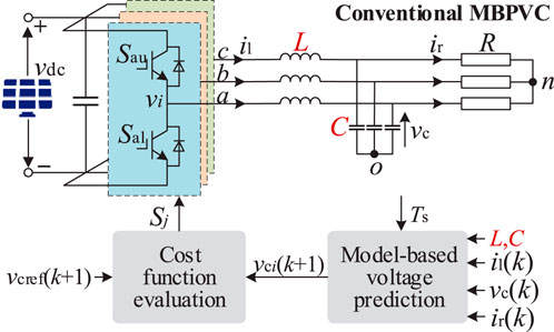
Figure 1. Control diagram of conventional MBPVC for GFI.
Figure 1 shows the GFI under conventional MBPVC method, where L is the filter inductor, C is the filter capacitor and R is the resistance load. vdc is the renewable energy DC source, vi is the voltage vector (i = 0∼7), vc is the capacitor voltage, il is the inductor current and ir is the load current. The three-phase switch functions Sj can be expressed as
Based on Figure 1, the mathematical model of the GFI can be expressed as
According to the forward Euler method, Equation 2 can be discretized as
Equation 3 can be further deduced as
According to Equation 4, by substituting different basic voltage vectors vi(k+1) and sampling vc(k), il(k), ir(k), along with parameters L and C, the model-based capacitor voltage can be predicted.
To select the optimal voltage vector from basic voltage vectors v0 to v7, a cost function g is defined as
where vcref is the capacitor voltage reference. The optimal voltage vector obtained from Equation 5 enables the control of the three-phase switches Sju and Sjl.
According to Equation 4, the accuracy of model-based voltage prediction vci(k+1) is influenced by the inductance L and capacitance C parameters. When the model parameters Lm and Cm do not match the actual parameters L and C, the prediction performance of vci(k+1) would be affected. Figure 2 illustrates the prediction error vcerr due to parameter mismatch, where the parameter error Pe = Lm/L = Cm/C. As seen in Figure 2, the prediction error vcerr increases with the parameter error Pe.
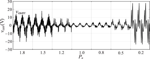
Figure 2. Voltage prediction error of conventional MBPVC under different parameter errors Pe.
In addition, based on Equation 4, the accuracy of model-based voltage prediction vci(k+1) is also influenced by the basic voltage vector vi(k+1). Due to the limited number of basic voltage vectors vi(k+1) in GFIs, the prediction error vcerr is also affected. Figure 3 illustrates the prediction error vcerr due to the application of basic voltage vector vi(k+1), where different voltage references vcref is set. As seen in Figure 3, the prediction error vcerr consistently remains around 5 V.
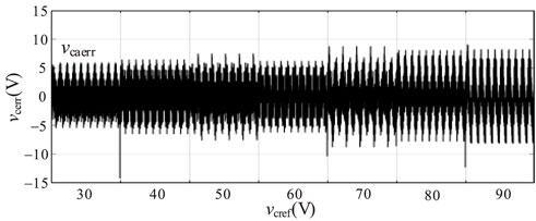
Figure 3. Voltage prediction error of conventional MBPVC under voltage references voref.
To mitigate the impact of parameter variations on the voltage prediction, a model-free predictive voltage control (MFPVC) method is proposed, as shown in Figure 4. This method is composed of model-free voltage prediction and optimal switching sequence. The former is utilized for eliminating parametric effect and the latter is utilized for reducing prediction errors.
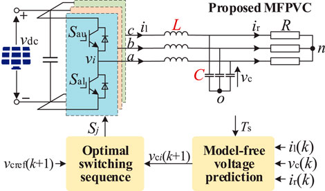
Figure 4. Control diagram of proposed MFPVC for GFI.
According to Equation 2, the ULDM of the GFI can be expressed as
where α = Ts/L/C, Ui = vi−vc, F=(il−ir)/C + F0, F0 are the gain, input, concentrated disturbance and nonlinear disturbance of the ULDM.
Based on Equation 6, the capacitor voltage gradient gci can be obtained as
Similarly, Equation 7 can be deduced as
Subtracting Equation 8 from Equation 7 yields that
Since the GFI usually operates at a high sampling and control frequency, it can be assumed that F(k)−F(k−1)≈0 (Cortes et al., 2009). Therefore, Equation 9 can be further simplified to
Based on Equation 10, the gain of the ULDM can be expressed as
Substituting Equation 11 into Equation 7, the concentrated disturbance F of the ULDM can be expressed as
Using α from Equation 11 and F(k) from Equation 12, the model-free voltage prediction vci(k+1) is obtained as
It can be observed from Equation 13 that the capacitor voltage can be predicted based on the obtained gain and concentrated disturbance of the ULDM, which are obtained from the measuring voltage data, eliminating parametric effect on voltage prediction.
It should be noted that the calculation of α and F in the ULDM would have a larger error when the sampling frequency is low, leading to poor control effect of MFPC. To effectively estimate the α and F in the ULDM, the linear extended-state-observer (LESO) is designed to estimate the α and F in the ULDM. The system state equation in Equation 6 can be written as
where δ1 and δ2 are the error gain of the voltage estimation and the concentrated disturbance estimation, respectively. The superscript ^ represents the estimated value. Equation 14 can be discretized and expressed as
The matrix form of Equation 15 can be expressed as
In order to ensure the stability of the LESO, the eigenvalue of Equation 16 should be set in the unit circle of the z-plane. The characteristic polynomial of Equation 16 can be expressed as
where I is the second-order identity matrix. To obtain better robustness, the characteristic polynomial can be set as
where ω0 is the bandwidth of the LESO. By combining Equations 17, 18, error gains δ1 and δ2 can be obtained as
By substituting the error gains δ1 and δ2 in Equation 19 into Equation 15, the observation of concentrated disturbance F(k+1) can be achieved. To respond to the nonlinear changes of the GFI, the adaptive strengthening factor is designed in the LESO. Equation 14 can be further expressed as
where τ is the adaptive strengthening factor, which can be expressed as
where θ1 and θ2 are the system parameter vectors, which can be estimated in real time using the least square method, as
where φ = [τ e]T, θ = [θ1 θ2]T, λ is the forgetting factor, λ∈[0.9,1]. K and P are the intermediate variables of the identification process, where the initial value of P(0) can be set to 106. By combining the adaptive strengthening factor τ(k) in Figure 5 and the forward Euler method, Equation 20 can be discretized as
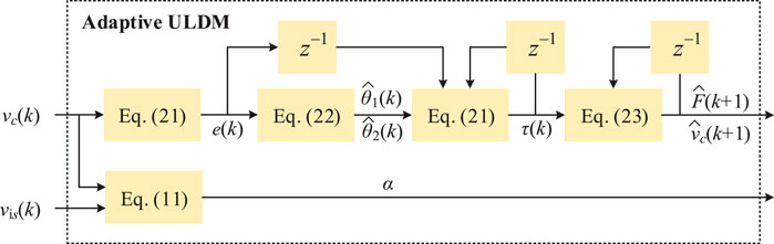
Figure 5. Diagram of adaptive ULDM.
The ULDM relies on real-time estimation of the concentrated disturbance F and the gain α. The LESO dynamically adjusts these parameters by observing voltage tracking errors and updating
To reduce the error of the proposed model-free voltage prediction, the basic voltage vector vi(k+1) in Equation 13 could be replaced with the combined voltage vector vis(k+1) (s = 1, … 6), which is composed of two basic non-zero voltage vectors vi_o, vi_t (v1∼v6), and two zero voltage vectors vi_z (v0, v7). The optimal switching sequence of the combined voltage vector corresponding to each sector is summarized in Table 1. From Table 1, it can be observed that vi_o is v1, vi_t is v2, and vi_z is v0 and v7 in section I. In other sections, vi_o and vi_t are replaced with others non-zero voltage vectors.
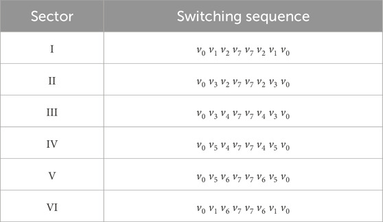
Table 1. Optimal switching sequence.
The durations tvio, tvit and tviz corresponding to vi_o, vi_t, and vi_z, respectively, can be obtained based on the deadbeat principle, as
Based on the durations tvio, tvit and tviz from Equation 24 and the optimal switching sequence in Table 1, the model-free voltage prediction with optimal switching sequence can be obtained as
Based on Equations 7, 25 can be simplified as
Based on Equation 16, the model-free voltage prediction with optimal switching sequence can be obtained, which not only eliminate parametric effect, but also improve accuracy of voltage prediction, enabling the capacitor voltage performance in GFIs.
Figure 6 illustrates the implementation flowchart of the proposed MFPVC strategy for GFIs. Initially, the capacitor voltage vc(k)∼vc(k−2) and voltage vector vis(k)∼vis(k−2) are sampled and substituted into Equations 11, 23 to calculate the gain α and the concentrated disturbance F(k) of the ULDM, respectively. Subsequently, Equation 13 is used to predict the capacitor voltage vci(k+1) corresponding to the basic voltage vector. By integrating the concept of deadbeat control and using Equation 24, the durations tvio, tvit and tviz corresponding to the non-zero voltage vectors vi_o, vi_t, and two zero voltage vectors vi_z, respectively, can be obtained. Based on the durations tvio, tvit and tviz, the model-free voltage prediction with optimal switching sequence can be obtained with Equation 26, eliminating the influence of parameters on the voltage prediction. The combined voltage vector is substituted into Equation 5 to evaluate the prediction error corresponding to each combined voltage vector. The combined voltage vector with smallest prediction error is selected as the optimal vector. The three-phase switch signals are applied based on Equation 1 in the next control period.
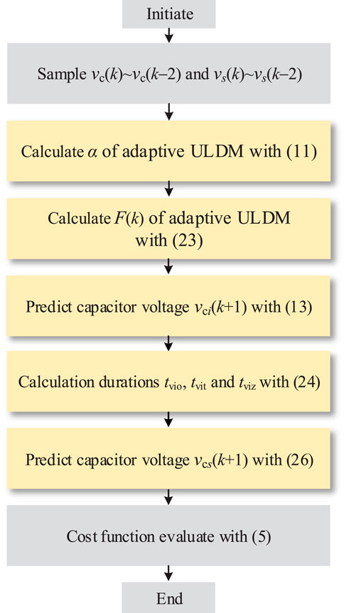
Figure 6. Proposed MFPVC for GFI.
To validate the effectiveness of the proposed MFPVC method, this section compares the grid-forming voltage performance of the conventional MBPVC method (Zheng et al., 2021), the conventional MFPVC method (Su et al., 2024), and the proposed MFPVC. The comparisons are conducted using the three-phase renewable energy grid-forming inverter experimental platform, as shown in Figure 7. The controller utilized is the TMS320C28335, and the experimental parameters are listed in Table 2.
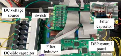
Figure 7. Experimental platform of GFI.

Table 2. Systems parameters.
Figure 8 compares the steady-state voltage performance of the proposed MFPVC method, the conventional MBPVC method, and the conventional MFPVC method. The capacitor voltage reference vcref is set at 80 V.
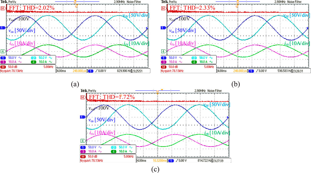
Figure 8. Experimental comparison of steady-state voltage performance. (a) Conventional MBPVC; (b) Conventional MFPVC; (c) Proposed MFPVC.
As shown in Figure 8a, when the conventional MBPVC method is applied, the steady-state voltage performance is good, with a Total Harmonic Distortion (THD) of 2.02%. In Figure 8b, the steady-state voltage performance reduces when the conventional MFPVC method is used, increasing the THD to 2.33%.
As illustrated in Figure 8c, the proposed MFPVC method achieves a voltage performance similar to that of the MBPVC method, with a THD of 1.72%, verifying the effectiveness of the proposed MFPVC method.
Figure 9 compares the dynamic-state voltage performance of the proposed MFPVC method, the conventional MBPVC method, and the conventional MFPVC method. The capacitor voltage reference vcref is changed from 80 V to 50 V.
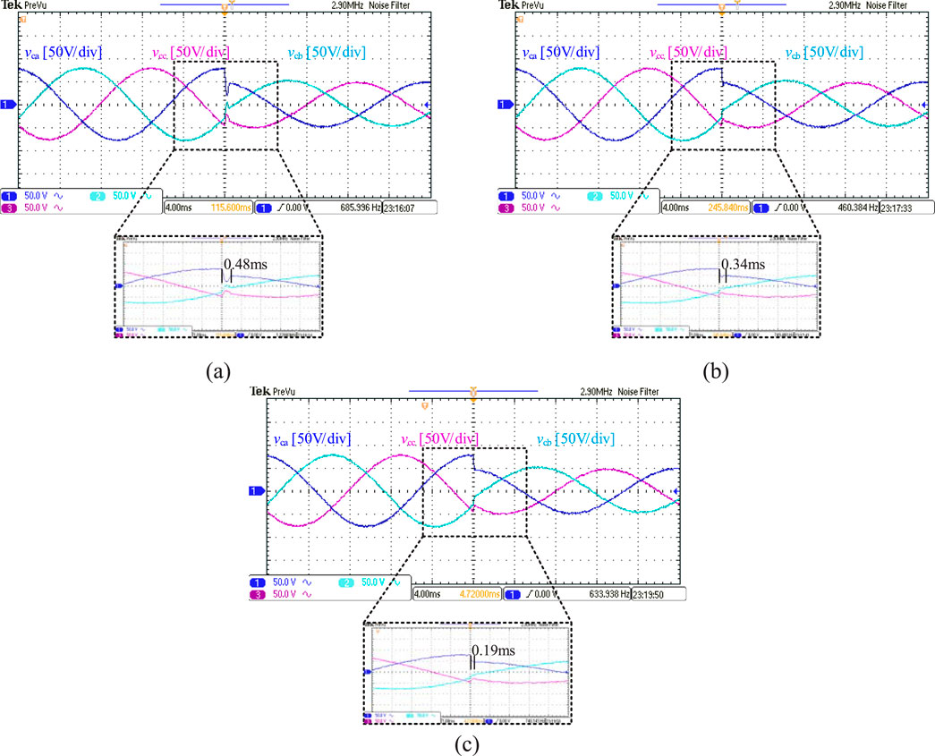
Figure 9. Experimental comparison of dynamic-state voltage performance. (a) Conventional MBPVC; (b) Conventional MFPVC; (c) Proposed MFPVC.
As shown in Figure 9a, when the conventional MBPVC method is applied, its dynamic-state voltage performance is relatively poor, with a response speed of 0.48 ms. In Figure 9b, the dynamic voltage performance improves when the conventional MFPVC method is used due to that the conventional MFPVC is applied based on the voltage and current difference, which is simpler than conventional mathematical model, reducing the response speed to 0.34 ms.
As illustrated in Figure 9c, the proposed MFPVC method achieves the best dynamic-state voltage performance due to the use of adaptive ULMD, with a response speed of 0.19 ms, verifying the effectiveness of the proposed MFPVC method.
Figure 10 compares the robustness voltage performance of the proposed MFPVC method, the conventional MBPVC method, and the conventional MFPVC method. The capacitor voltage reference vcref is 80 V. The parameter error Pe is changed from 0.2 to 1.8.
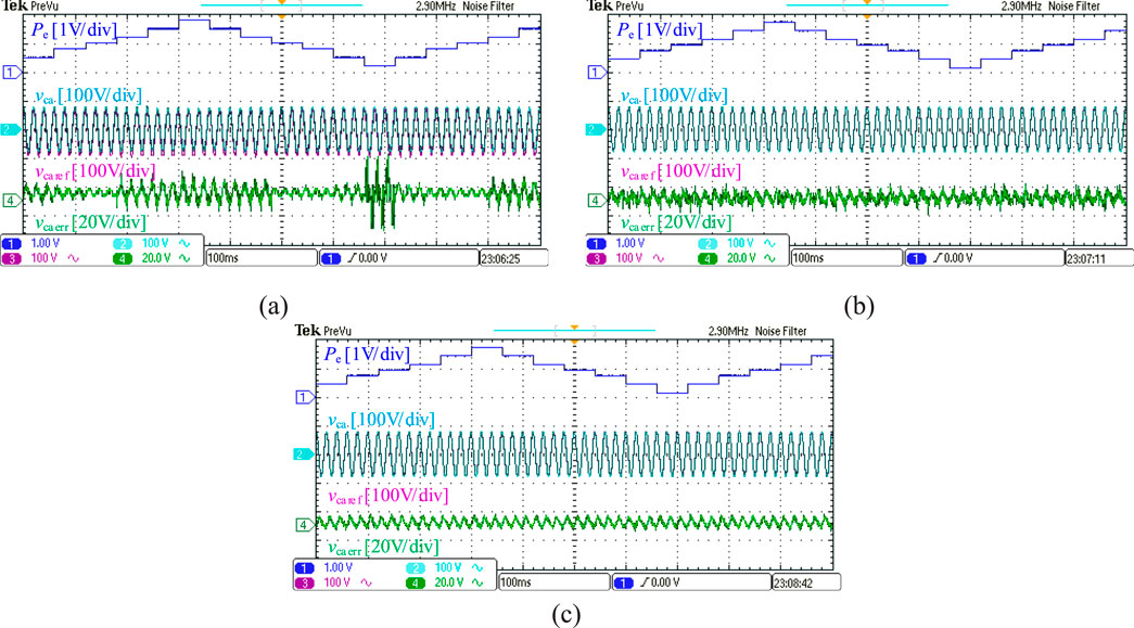
Figure 10. Experimental comparison of robustness voltage performance. (a) Conventional MBPVC; (b) Conventional MFPVC; (c) Proposed MFPVC.
As shown in Figure 10a, when the conventional MBPVC method is applied, its robustness voltage performance is obviously affected due to that the conventional MBPVC depends on the accurate parameter. When parameter errors Pe increase, the voltage errors also increase. In Figure 10b, the robustness voltage performance improves when the conventional MFPVC method is used due to the use of the voltage and current difference, which replaces the conventional mathematical model, improving the robustness. However, conventional MFPVC is easily affected by sampling noise, increasing voltage errors.
As illustrated in Figure 10c, the proposed MFPVC method achieves the best robustness voltage performance due to the use of ultra-local data-model, verifying the effectiveness of the proposed MFPVC.
As illustrated in Table 3, the proposed MFPVC with THD of 1.72% achieves comparable steady-state voltage performance to the conventional MBPVC with THD of 2.02% and superior voltage performance compared to the conventional MFPVC with THD of 2.33%. Besides, the dynamic performance of proposed MFPVC is 0.29 ms, which has the best dynamic-state voltage performance compared to conventional MBPVC method and conventional MFPVC method. Furthermore, proposed MFPVC demonstrates the best robustness compared to conventional MBPVC and conventional MFPVC under mismatched parameters.
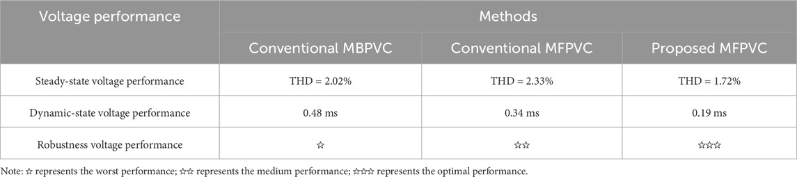
Table 3. Voltage performance comparison.
This paper proposes an improved model-free predictive voltage control (MFPVC) for grid-forming inverters (GFIs) in renewable energy systems. The proposed MFPVC establishes and updates the adaptive ultra-local data-model (ULDM) for the GFI, eliminating the impact of parameters on voltage prediction. Additionally, to further reduce prediction errors, the proposed MFPVC designs an optimal switching sequence and calculates the duration using the deadbeat principle.
Various experiments are conducted to validate the effectiveness of the proposed MFPVC, showing: (1) When parameters are accurate, the proposed MFPVC with THD of 1.72% achieves comparable steady-state performance to the conventional MBPVC with THD of 2.02% and superior voltage performance compared to the conventional MFPVC with THD of 2.33%; (2) The dynamic performance of the proposed method is 0.29 ms faster than that of the conventional MBPVC method and 0.15 ms faster than that of the conventional MFPVC method; (3) It demonstrates greater robustness compared to conventional MBPVC under mismatched parameters.
In the future, we can study the application of the proposed MFPVC in LCL filter grid-connected inverters and study the application of the proposed MFPVC in high-power and low-switching frequency GFIs, improving the application range of the proposed MFPVC in more complex micro-grid.
The original contributions presented in the study are included in the article/supplementary material, further inquiries can be directed to the corresponding author.
YL: Conceptualization, Writing–original draft, Writing–review and editing. JZ: Funding acquisition, Writing–review and editing. FH: Investigation, Writing–review and editing.
The author(s) declare that financial support was received for the research, authorship, and/or publication of this article. This research was funded by State Grid Fujian Electric Power Technology Project, grant number 52132024000H.
Author YL was employed by Country State Grid Fujian Electric Power Co., Ltd. Authors JZ and FH were employed by Putian Electric Power Supply Company of State Grid Fujian Electric Power Co., Ltd.
The authors declare that no Generative AI was used in the creation of this manuscript.
All claims expressed in this article are solely those of the authors and do not necessarily represent those of their affiliated organizations, or those of the publisher, the editors and the reviewers. Any product that may be evaluated in this article, or claim that may be made by its manufacturer, is not guaranteed or endorsed by the publisher.
Cortes, P., Ortiz, G., Yuz, J. I., Rodriguez, J., Vazquez, S., and Franquelo, L. G. (2009). Model predictive control of an inverter with output $LC$ filter for UPS applications. IEEE Trans. Industrial Electron. 56 (6), 1875–1883. doi:10.1109/tie.2009.2015750
Heydari, R., Young, H., Bahamonde, F. F., Zadeh, S. V., Castano, C. G., Sabzevari, S., et al. (2022). Model-free predictive control of grid-forming inverters with LCL filters. IEEE Trans. Power Electron. 37 (8), 9200–9211. doi:10.1109/TPEL.2022.3159730
Hu, C., Xu, W., Yin, Z., Rui, T., Zhang, Z., Lu, G., et al. (2024). A novel modulated model-free predictive control for LC-filtered grid-forming inverters with double-difference updating. IEEE Trans. Industrial Electron. 71 (9), 10806–10817. doi:10.1109/tie.2023.3335463
Hu, C., Yin, Z., Rui, T., Zhang, Z., Shen, W., Cao, W., et al. (2023). A novel double-voltage-vector model-free predictive current control method for two-level voltage source inverters. IEEE Trans. Industrial Electron. 70 (6), 5872–5884. doi:10.1109/tie.2022.3199947
Jin, N., Chen, M., Guo, L., Li, Y., and Chen, Y. (2022). Double-vector model-free predictive control method for voltage source inverter with visualization analysis. IEEE Trans. Industrial Electron. 69 (10), 10066–10078. doi:10.1109/tie.2021.3128905
Lian, C., Xiao, F., Liu, J., and Gao, S. (2023). Parameter and VSI nonlinearity hybrid estimation for PMSM drives based on recursive least square. IEEE Trans. Transp. Electrification 9 (2), 2195–2206. doi:10.1109/tte.2022.3206606
Liu, T., and Wang, X. (2022). Physical insight into hybrid-synchronization-controlled grid-forming inverters under large disturbances. IEEE Trans. Power Electron. 37 (10), 11475–11480. doi:10.1109/tpel.2022.3168902
Long, B., Yang, W., Hu, Q., Guerrero, J. M., Carcia, C., Rodriguez, J., et al. (2022b). Moth–flame-optimization-based parameter estimation for FCS-MPC-Controlled grid-connected converter with LCL filter. IEEE J. Emerg. Sel. Top. Power Electron. 10 (4), 4102–4114. doi:10.1109/jestpe.2022.3140228
Long, B., Zhu, Z., Yang, W., Chong, K. T., Rodriguez, J., and Guerrero, J. M. (2022a). Gradient descent optimization based parameter identification for FCS-MPC Control of LCL-type grid connected converter. IEEE Trans. Industrial Electron. 69 (3), 2631–2643. doi:10.1109/tie.2021.3063867
Rui, T., Feng, Z., Hu, C., Yin, Z., Cao, W., Lu, G., et al. (2024). Double-vector model-free predictive current control method for voltage source inverters with sampling noise suppression. IEEE Trans. Industrial Electron. 71 (6), 5797–5806. doi:10.1109/tie.2023.3273241
Rui, T., Yin, Z., Hu, C., Lu, G., Zhang, P., Shen, W., et al. (2023). Modulated model-free predictive current control for voltage source inverters with stagnation elimination and sampling disturbance suppression. IEEE Trans. Power Electron. 38 (6), 6996–7008. doi:10.1109/tpel.2023.3247811
Samanta, S., Lagoa, C. M., and Chaudhuri, N. R. (2024). Nonlinear model predictive control for droop-based grid forming converters providing fast frequency support. IEEE Trans. Power Deliv. 39 (2), 790–800. doi:10.1109/tpwrd.2023.3336868
Song, G., Cao, B., and Chang, L. (2022). Review of grid-forming inverters in support of power system operation. Chin. J. Electr. Eng. 8 (1), 1–15. doi:10.23919/cjee.2022.000001
Su, G., Li, H., Li, Z., and Zhou, Y. (2024). Model-free control of permanent magnet synchronous linear motor based on ultra-local model. Chin. J. Electr. Eng. 10 (4), 73–82. doi:10.23919/CJEE.2024.000050
Tan, S., Xie, P., Guerrero, J. M., Vasquez, J. C., Alcala, J. M., Carreno, J. E. M., et al. (2024). Lyapunov-based resilient cooperative control for DC microgrid clusters against false data injection cyber-attacks. IEEE Trans. Smart Grid 15 (3), 3208–3222. doi:10.1109/tsg.2023.3332946
Yin, Z., Deng, F., Ghanem, A., Kaddah, S. S., and Abulanwar, S. (2024b). PLPR-based predictive control for LCL-filtered voltage source inverters. IEEE Trans. Power Electron. 39 (6), 7468–7480. doi:10.1109/tpel.2024.3371053
Yin, Z., Deng, F., Kaddah, S. S., and Abulanwar, S. (2024a). Modulated PLPR-based predictive control with noise suppression for LC-filtered voltage source inverters. IEEE Trans. Industrial Electron. 72 (3), 2588–2598. doi:10.1109/tie.2024.3433438
Zhang, Y., Jin, J., and Huang, L. (2021). Model-free predictive current control of PMSM drives based on extended state observer using ultralocal model. IEEE Trans. Industrial Electron. 68 (2), 993–1003. doi:10.1109/tie.2020.2970660
Zhao, T., Zhang, M., Wang, C., and Sun, Q. (2023). Model-free predictive current control of three-level grid-connected inverters with LCL filters based on kalman filter. IEEE Access 11, 21631–21640. doi:10.1109/access.2023.3251410
Keywords: grid-forming inverter, model-free predictive voltage control, adaptive ultra-local data-model, optimal switching sequence, parameter robustness
Citation: Lin Y, Zhu J and He F (2025) An improved model-free predictive voltage control for grid-forming inverter with adaptive ultra-local data-model in renewable energy system. Front. Energy Res. 13:1526992. doi: 10.3389/fenrg.2025.1526992
Received: 12 November 2024; Accepted: 10 March 2025;
Published: 24 March 2025.
Edited by:
Yuqing Dong, The University of Tennessee, Knoxville, United StatesReviewed by:
Kaiqi Sun, Shandong University, ChinaCopyright © 2025 Lin, Zhu and He. This is an open-access article distributed under the terms of the Creative Commons Attribution License (CC BY). The use, distribution or reproduction in other forums is permitted, provided the original author(s) and the copyright owner(s) are credited and that the original publication in this journal is cited, in accordance with accepted academic practice. No use, distribution or reproduction is permitted which does not comply with these terms.
*Correspondence: Yifu Lin, bGlueWlmdTIwMjRAMTYzLmNvbQ==
Disclaimer: All claims expressed in this article are solely those of the authors and do not necessarily represent those of their affiliated organizations, or those of the publisher, the editors and the reviewers. Any product that may be evaluated in this article or claim that may be made by its manufacturer is not guaranteed or endorsed by the publisher.
Research integrity at Frontiers
Learn more about the work of our research integrity team to safeguard the quality of each article we publish.