- 1Guangxi Power Grid Co., Ltd., Nanning, China
- 2Electric Power Research Institute, CSG, Guangzhou, China
To address the technical challenge of rapid and reliable interruption of DC faults in offshore wind power DC collection and transmission systems, which are critical for large-scale renewable energy integration, this paper proposes an integrated multi-port DC circuit breaker (DCCB) with bus fault clearing capability based on a dual H-bridge configuration. By extending a pair of bridge arms in the H-bridge to connect to the DC bus and employing diodes in the load commutation switches (LCSs) to form the second H-bridge, the proposed DCCB not only achieves conventional line fault clearing but also has the ability to interrupt bus faults. A five-terminal offshore wind power DC transmission system simulation model was built in PSCAD/EMTDC to verify the performance of the DCCB under various operating conditions. The results demonstrate that the proposed multi-port DCCB can protect multiple DC lines effectively under different conditions.
1 Introduction
With the global energy shortage, renewable energy represented by wind power has become an important method for providing electricity to humanity. Offshore wind power, known for its stable operation of wind turbines, has garnered significant attention from researchers in the field of electrical power (Xiao et al., 2024; An et al., 2017; Smeets, 2015). The integration of large-scale renewable energy sources, particularly offshore wind power, into the electrical grid presents unique challenges and opportunities. There are two main methods for integrating offshore wind power into the grid: high-voltage alternating current (HVAC) transmission and high-voltage direct current (HVDC) transmission. HVAC is suitable for nearshore wind power integration, while HVDC is more appropriate for offshore wind farms located farther from the coast (Xiao et al., 2024). In the HVDC integration scheme, flexible HVDC transmission based on the modular multilevel converter (MMC) is currently the only method internationally used for large-scale, long-distance offshore wind power transmission to onshore grids. This is due to its advantages, such as the absence of commutation failure issues, independent control of active and reactive power, and low harmonic levels. Recently, a large-scale offshore wind power flexible HVDC transmission project with a transmission capacity of 6000 MW is being planned in southern China. This project aims to transmit offshore wind power to the onshore grid via three submarine cables, which will then be connected to the load center through two DC overhead lines. However, to reduce the size, weight, and construction complexity of the offshore converter station, the offshore sending-end converter station is designed to use only half-bridge submodules. Consequently, a significant number of DC circuit breakers (DCCBs) are required to provide DC fault clearing capability (Li et al., 2016; Tang et al., 2014; Xiao et al., 2022; Guo et al., 2022).
DCCBs are typically categorized into mechanical DCCBs (Shi et al., 2022; Wen et al., 2018; Hajian et al., 2015), solid-state DCCBs (Corzine, 2017; Overstreet et al., 2014; Keshavarzi et al., 2017; Liu et al., 2017a), and hybrid DCCBs (Majumder et al., 2017; Hedayati and Jovcic, 2018; Hassanpoor et al., 2015; Xu et al., 2021; Li et al., 2019; Abedrabbo et al., 2020). Hybrid DCCBs combine the benefits of both mechanical and solid-state variants. They utilize conducting branch for the flow of normal operating currents and employ the main breaker (MB) to interrupt fault currents. This design results in reduced on-state losses and facilitates fast interruption of fault currents.
In November 2012, ABB announced the development of the world’s first two-port hybrid DCCB for HVDC with a breaking time of 5 ms, a rated voltage of 320 kV, and a current breaking capacity of approximately 9 kA (Callavik et al., 2012). Tsinghua University, Beijing Electric Power Equipment General Factory, Huazhong University of Science and Technology, and State Grid Smart Grid Research Institute respectively proposed three types of DCCB solutions for the Zhangbei DC grid: coupled negative pressure, mechanical, and hybrid schemes. The hybrid scheme proposed by the Smart Grid Research Institute was officially put into operation in June 2020, with a voltage rating of 535 kV, a maximum current breaking capacity of 25 kA, and a breaking time of 3 ms. However, the MB in the hybrid DCCB necessitates a considerable number of full controlled electronic devices to meet the requirement for withstand voltage, through-current, and bidirectional breaking. This results in substantial costs, making it unsuitable for deployment in meshed DC grids. To address this challenge, the concept of multiport DCCBs has emerged to reduce the cost of two-port DCCBs by leveraging device reuse (Mokhberdoran et al., 2018; Kontos et al., 2018; Liu et al., 2017b). A multiport DCCB proposed in (Mokhberdoran et al., 2018) achieves this by reusing mechanical switches and half of the full controlled electronic devices in the MB. However, this DCCB lacks the capability to transfer power on the normal line following a line fault, and multiple MBs are still required to realize bidirectional fault current interruption. In pursuit of bidirectional fault current interruption using only unidirectional full controlled electronic devices, a multiline DCCB utilizing an H-bridge structure has been proposed. Kontos et al. (2018) utilizes a conducting branch to form an H-bridge, enabling rectification by issuing different switching commands in response to various line faults. This allows its single MB to achieve bidirectional fault current interruption using unidirectional full controlled electronic devices in series. However, this DCCB necessitates sending 2n + 2 independent switching signals to handle DC faults in the n-port case, which could potentially reduce its reliability. To mitigate this issue, Liu et al. (2017a) proposes an assembly DCCB that shifts the fault current interruption components from a series structure to a parallel structure while changing the centralized arrangement of all components in the ABB hybrid DCCB to a distributed layout. This modification significantly improves reliability by reducing the number of independent switching signals required to isolate cable faults to just 6. However, the assembly DCCB requires actively grounding specific points on the DC bus when interrupting line faults, which may broaden the fault’s impact on the system.
In an ideal simulation environment, the conducting branches of each cable in the multi-port DCCB can be directly connected to a single point, eliminating the need for a “DC bus” concept, as no DC faults would uncontrollably occur at this point. Therefore, the multi-port DCCB topologies proposed in Mokhberdoran et al. (2018), Kontos et al. (2018), Liu et al. (2017b) do not possess the capability to isolate DC bus faults. However, in practical engineering, if the conducting branches, which carry the majority of the current, are placed too close to each other, significant electrical coupling may occur between them. As a result, in real-world applications, it is necessary to maintain a certain distance between the conducting branches, which means they will be connected to a “DC bus” with some physical separation. In such cases, DC bus faults may occur, potentially causing severe impacts on the DC system.
To enhance circuit breaker cost-effectiveness while minimizing impact on the DC system, reduce the number of switching signals needed to improve reliability, and address the challenge of isolating DC bus faults, this paper proposes a dual H-bridge integrated multi-port DC circuit breaker and its control strategy. The design extends an additional pair of bridge arms from the H-bridge in the integrated multi-port DCCB to connect to the DC bus and employs diodes in the load commutation switches (LCS) to form the second H-bridges, enabling the clearing of bus faults. This paper will sequentially introduce the circuit topology and control strategy of the dual H-bridge integrated multi-port DCCB and compare its technical and economic aspects with existing multi-port DCCB solutions. Finally, a large-scale offshore wind power DC collection and transmission system will be modeled in PSCAD/EMTDC for simulation and verification of the proposed solution.
2 Two grid structures for long-distance DC transmission and the limitations of existing multiport DC circuit breaker research
Typical DC grid structures suitable for long-distance DC transmission are illustrated in Figure 1. Figure 1A is more commonly applied in onshore scenarios and requires a total of two DC buses. Power generated by the sending-end MMC is aggregated through one DC bus and then transmitted via multiple DC lines to the second DC bus at the receiving end, where the power is distributed to each receiving-end MMC. Figure 1B is more frequently used in offshore renewable energy grid integration scenarios. It connects offshore wind farms to onshore load points through a single DC bus, thereby reducing the demand for onshore transmission corridors required for integrating offshore wind power.
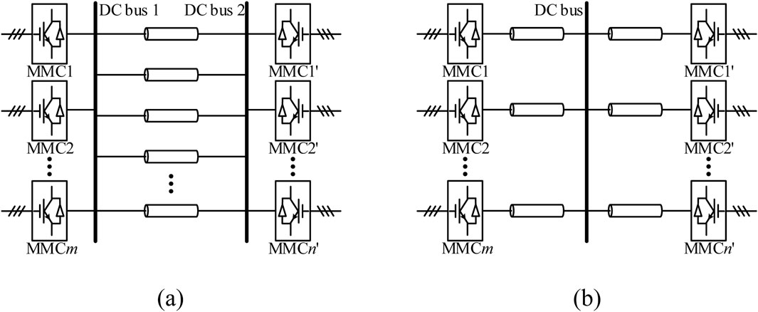
Figure 1. Two grid structures for long-distance DC transmission. (A) More suitable for onshore renewable energy integration. (B) More suitable for offshore renewable energy integration.
As observed from Figure 1, regardless of the specific DC grid structure, the DC bus plays a critical role. Consequently, the capability to clear DC faults on the DC bus is an important criterion for evaluating DC circuit breaker technology. However, existing studies on multi-port DC circuit breakers often confuse the concept of the DC bus with that of MMC-side lines. For example, (Mokhberdoran et al., 2018), as one of the pioneering papers with significant influence on the direction of multi-port DC circuit breakers, defined the typical schemes for two-port and multi-port DCCBs, and based on this, proposed multi-port DC circuit breakers, as shown in Figure 2. In this figure, the blue boxes indicate the areas considered as the DC bus by the authors. However, the blue-boxed areas only connect the MMC-side line to fault interruption component, which do not carry significant current under normal operating conditions; thus, they do not represent the actual DC bus. In contrast, the red boxes directly connect the conducting branches of multiple lines. In practical engineering, to prevent electrical coupling between these conducting branches, they cannot be directly connected to the same “point” and must be spaced apart. The connecting lines between these conducting branches constitute the true “DC bus.”
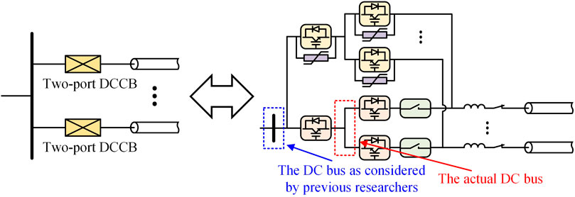
Figure 2. The circuit topologies of multi-port DC circuit breakers proposed in Mokhberdoran et al. (2018).
3 Topology
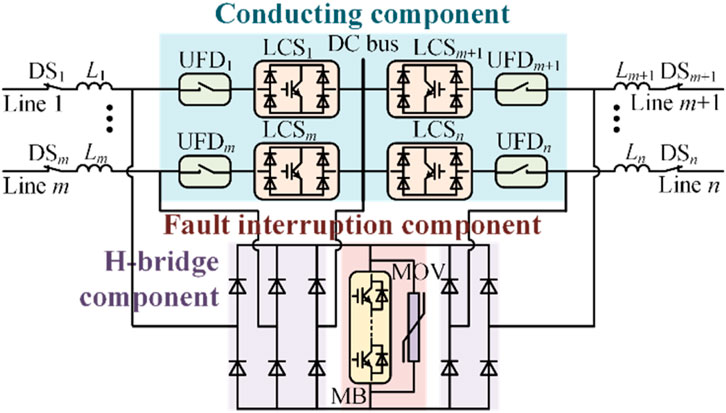
As shown in Figure 3, the dual H-bridge integrated multi-port DCCB with bus fault-clearing capability consists of three main components: the conducting component, the H-bridge component, and the fault interruption component. The specific composition of each component is as follows:
1. Conducting component: This structure is fundamentally similar to the conducting branch of ABB’s hybrid two-port DCCB, comprising the LCS in series with the ultra-fast disconnector (UFD). The key difference lies in the LCSs of the dual H-bridge integrated multi-port DCCB, which employ unidirectional series-connected insulate-gate bipolar transistors (IGBTs) and forms an H-bridge using diodes. This design topology is intended to achieve bus fault interruption while maintaining cost-effectiveness. During normal operation, the current primarily flows through the conducting component.
2. H-bridge component: This component is composed of diodes. The H-bridge component rectifies the fault current flowing through the fault interruption component into the same direction, regardless of which line experiences a fault.
3. Fault interruption component: This structure is fundamentally similar to the fault interruption component of ABB’s hybrid two-port DCCB, consisting of a MB connected in parallel with metal oxide varistors (MOV). The key difference is that, due to the presence of the H-bridge component in the dual H-bridge integrated multi-port DCCB, the MB here only requires unidirectional series-connected IGBTs.
In summary, the dual H-bridge integrated multi-port DCCB extends an additional pair of bridge arms from the H-bridge component to connect to the DC bus. Additionally, both the LCSs and the H-bridge component utilize diodes to form the H-bridge structure. This configuration endows the DCCB with the capability to clear bus faults.
4 Control strategies
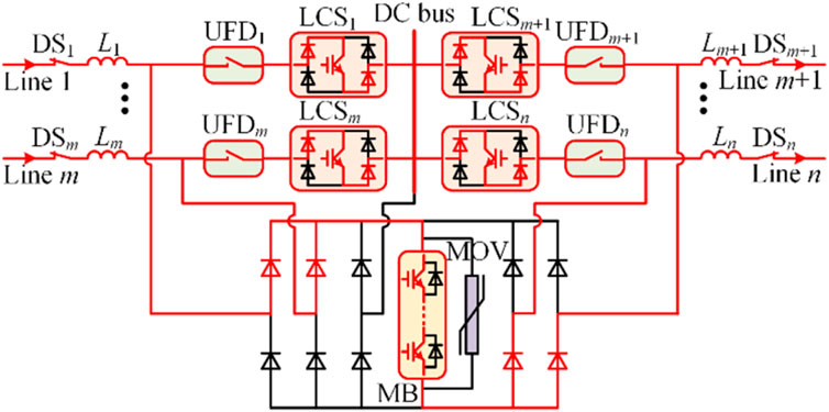
During normal operation, all switches in the dual H-Bridge integrated multi-port DCCB are closed. At this time, the current flows through the paths shown in Figure 4.
As shown in Figure 4, since all LCSs and the MB are closed, the normal operating current flows through both the parallel conducting component and the fault interruption component. However, because the number of series-connected IGBTs in the LCSs is significantly fewer than in the MB, the current flowing through the MB during normal operation is minimal, resulting in very low on-state losses.
4.1 DC line fault
Taking the DC fault on line m + 1 as an example, the fault interruption operation of the dual H-Bridge integrated multi-port DCCB is illustrated in Figure 5.
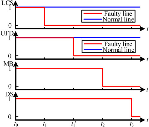
1. t0 < t < t1: Fault detection stage. At t = t0, a short-circuit fault occurs on line m + 1. At this time, the fault current flows through the path shown in Figure 5A, primarily passing through the conducting component towards the faulty cable. Once the fault on line m + 1 is detected, a disconnect command is sent to LCSm+1. The time required for fault detection mainly depends on the specific fault detection method. Typically, this time is in the range of 1–2 ms.
2. t1 < t < t2: Load commutation stage. At t = t1, LCSm+1 receives the disconnect command and opens, causing the current flowing through LCSm+1 and UFDm+1 to rapidly drop to zero. At this time, the fault current flows through the path shown in Figure 5B. Next, a disconnect command is sent to UFDm+1, and after a brief delay, UFDm+1 fully opens, relieving LCSm+1 from any further stress. Typically, the operating time of LCS is 50 μs ∼ 250 μs (including 0–200 μs commutation time from LCS branch to MB branch), and of UFD is about 2 ms.
3. t2 < t < t3: Fault interruption stage. At t = t2, a disconnect signal is sent to the MB. After a brief delay, MB receives the disconnect signal and fully opens, redirecting the fault current from MB to the MOV, as shown in Figure 5C. Under the action of the MOV, the fault current rapidly decreases to zero, as shown in Figure 5D. Subsequently, the mechanical switch DSm+1 in line m + 1 opens, completely isolating the fault and allowing the remaining healthy lines to resume normal current flow. Typically, the operating time of the MB is 50 μs. Once the MB fully opens and the MOV is engaged, the fault current quickly drops to zero, and the DC fault no longer affects the system. Therefore, the energy dissipation time of the MOV and the time taken for the DS to trip are generally not studied.
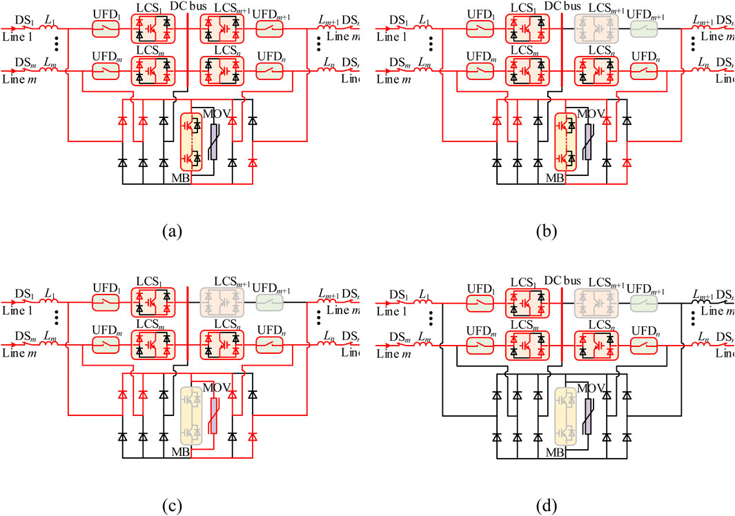
Figure 5. Fault interruption operation under DC line fault. (A) t0 < t < t1. (B) t1 < t < t2. (C) t2 < t < t3. (D) t3 < t < t4.
The switching signals of the proposed control strategy under DC line fault conditions are shown in Figure 6.
4.2 DC bus fault
When a DC bus fault occurs, the fault interruption operation of the dual H-bridge integrated multi-port DCCB is shown in Figure 7.
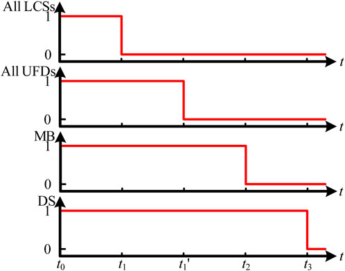
1. t0 < t < t1: Fault detection stage. At t = t0, a short-circuit fault occurs on the bus. At this time, the fault current flows through the path shown in Figure 7A, primarily passing through the conducting component towards the faulty cable. Once the system detects the bus fault, it sends a disconnect command to all LCSs. The time required for fault detection mainly depends on the specific fault detection method. Typically, this time is in the range of 1–2 ms.
2. t1 < t < t2: Load commutation stage. At t = t1, all LCSs receive the disconnect command and open, causing the current through all LCSs and UFDs to rapidly drop to zero. At this time, the fault current flows through the path shown in Figure 7B. Subsequently, disconnect commands are sent to all UFDs, and after a brief delay, all UFDs fully open, relieving all LCS from any further stress. Typically, the operating time of LCS is 50 μs ∼ 250 μs (including 0–200 μs commutation time from LCS branch to MB branch), and of UFD is about 2 ms.
3. t2 < t < t3: Fault interruption stage. At t = t2, a disconnect signal is sent to the MB. After a brief delay, MB receives the disconnect signal and fully opens, redirecting the fault current from MB to the MOV, as shown in Figure 7C. Under the action of the MOV, the fault current rapidly decreases to zero, as shown in Figure 7D. Subsequently, all DS open, completely isolating the fault. Typically, the operating time of the MB is 50 μs. Once the MB fully opens and the MOV is engaged, the fault current quickly drops to zero, and the DC fault no longer affects the system. Therefore, the energy dissipation time of the MOV and the time taken for the DS to trip are generally not studied.
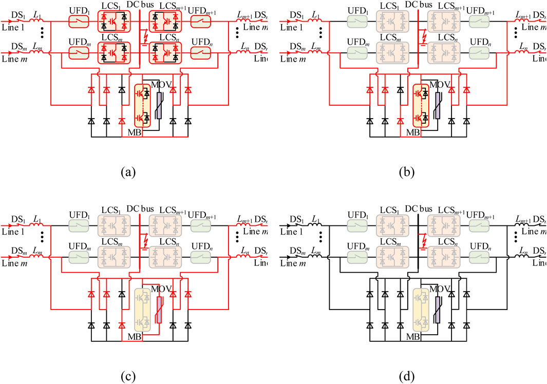
Figure 7. Fault interruption operation under DC line fault. (A) t0 < t < t1. (B) t1 < t < t2. (C) t2 < t < t3. (D) t3 < t < t4.
The switching signals of the proposed control strategy under DC bus fault conditions are shown in Figure 8.
It is worth noting that the proposed DCCB has high adaptability to installation positions. Whether installed in the positive or negative line of a bipolar DC system, it can reliably interrupt DC faults using the same fault interruption strategy. However, when the DCCB is installed in the negative line and used to interrupt a busbar fault, the 0 V “ground” will become the high potential. In this case, the current flow path will differ from the one shown in Figure 7, as illustrated in the path shown in Figure 9. At this point, the upper bridge arm of the newly added H-bridge will be activated.
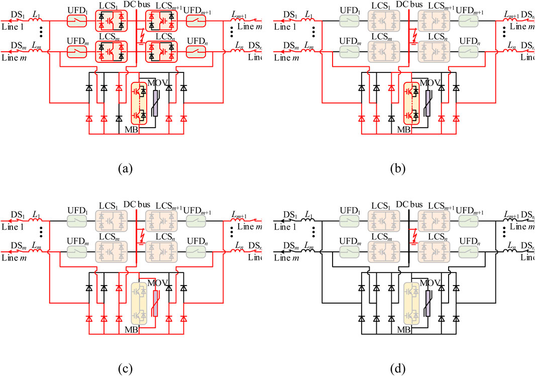
Figure 9. Fault interruption operation under DC line fault in the negative line. (A) t0 < t < t1. (B) t1 < t < t2. (C) t2 < t < t3. (D) t3 < t < t4.
5 Technical and economic analysis
In practical engineering, if the conducting branches of the cables, which primarily carry current during normal operation, are too close to each other, severe electrical coupling between the conducting branches can occur. Therefore, in practical applications, the conducting branches of the cables need to be spaced apart and connected to the same DC bus. In this situation, a DC bus fault may occur, which can severely impact the DC system.
Additionally, during the process of isolating DC faults with a multi-port DCCB, the system needs to send multiple different signals to various components of the DCCB. Each signal transmission and reception carries the risk of failure. If a signal fails to be sent or received, it could result in a component within the DCCB failing to operate, ultimately leading to a failure in isolating the DC fault and causing severe consequences for the DC system.
Therefore, the two key technical indicators for evaluating the technical and reliability aspects of a multi-port DCCB are: “the ability to isolate bus faults” and “the number of independent switching signals required to isolate the fault.”
Since ABB developed the world’s first hybrid DCCB with practical engineering significance in 2012, numerous scholars have since developed technically feasible two-port high-voltage DCCBs. However, two-port DCCBs are costly, bulky, and challenging to deploy widely in power grids like AC circuit breakers. As a result, the concept of multi-port DCCBs has been proposed, which aims to reduce costs by reusing some components from high-voltage DCCBs.
Therefore, economic performance is a crucial indicator for evaluating multi-port DCCBs. Provided that the technical reliability and functional capabilities of the multi-port DCCB are maintained, the fewer the number of components and the lower the cost, the better the economic performance of the DCCB.
This chapter will focus on the aforementioned two technical indicators and the economic indicator to conduct a techno-economic analysis and comparison of the proposed dual H-bridge integrated multi-port DCCB, the hybrid two-port DCCB introduced by ABB in Callavik et al., (2012), the multiport DCCB proposed in Mokhberdoran et al. (2018), the multiline DCCB in Kontos et al. (2018), and the assembly DCCB in Liu et al. (2017a).
5.1 Technical analysist
Based on the circuit topology and control strategy described earlier, the dual H-bridge integrated multiport DCCB possesses bus fault interruption capability. When a line fault occurs, the DCCB needs to send one switching signal to the LCS, one to the UFD, one to the MB, and one to the DS to isolate the line fault. In the event of a bus fault, the dual H-bridge integrated n-port DCCB must send n switching signals to the LCS, n switching signals to the UFD, one switching signal to the MB, and n switching signals to the DS to successfully isolate the bus fault.
The hybrid two-port DCCB proposed by ABB in Callavik et al. (2012) is also capable of clearing bus faults. When a line fault occurs, this DCCB needs to send one switching signal to the LCS, one to the UFD, one to the MB, and one to the DS. In the event of a bus fault, n ABB hybrid two-port DCCBs must send n switching signals to the LCS, n switching signals to the UFD, n switching signals to the MB, and n switching signals to the DS.
The multiport DCCB proposed in Mokhberdoran et al. (2018) does not have bus fault clearing capability. Additionally, when a line fault occurs, the n-port DCCB must send 2n switching signals to the LCS, one switching signal to the UFD, 2n switching signals to the MB, and one switching signal to the DS.
The multiline DCCB proposed in Kontos et al. (2018) does not have bus fault clearing capability. Additionally, when a line fault occurs, the n-line DCCB must send n switching signals to the LCSs, n switching signals to the UFDs, one switching signal to the MB, and one switching signal to the DS.
The assembly DCCB proposed in Liu et al. (2017b) does not have bus fault clearing capability. Additionally, when a line fault occurs, the n-port assembly DCCB must send one switching signal to the Accessory discharging switch, one switching signal to the LCS, one switching signal to the UFD, two switching signals to the MB, and one switching signal to the DS.
In summary, the technical analysis results of the aforementioned DCCB schemes in the n-port condition can be consolidated into Table 1.
As shown in Table 1, the ABB hybrid two-port DCCB scheme can effectively clear both line faults and bus faults while requiring a minimal number of switching signals, demonstrating excellent technical performance. However, since it does not reuse the MB, its economic efficiency is not superior.
The multiport DCCB, while achieving component reuse, significantly reduces technical performance compared to the ABB hybrid DCCB. It loses the capability to clear bus faults and requires an increase in the number of independent switching signals from 4 to 4n + 2 for isolating line faults.
The multiline DCCB reduces the number of independent switching signals required to isolate line faults from 4n + 2 in the multiport DCCB to 2n + 2 by modifying the circuit topology and control strategy. Despite the innovative introduction of the H-bridge structure into DCCB topology, there is still room for optimization.
The assembly DCCB changes the fault current interruption components from a series to a parallel structure and shifts from centralized to distributed placement of components, reducing the required independent switching signals to 6 when isolating line faults. This is only a 50% increase compared to the ABB DCCB and does not increase with the number of ports. However, the assembly DC circuit breaker requires actively short-circuiting and grounding a specific location of the DC bus when clearing line faults, which may exacerbate the impact of the fault on the system.
The dual H-bridge integrated DCCB extends the original H-bridge with an additional pair of bridge arms connected to the DC bus and utilizes diodes in the LCSs to form the second H-bridge, enabling bus fault clearing capability. Additionally, due to the reuse of the MB, the dual H-bridge integrated multi-port DCCB requires only 3n + 1 independent switching signals to isolate bus faults, fewer than the 4n signals required by the ABB hybrid DCCB scheme, thereby surpassing the ABB hybrid DCCB scheme in both technical performance and reliability.
5.2 Economic analysist
The quantities of components required for the circuit topologies of the ABB hybrid two-port DCCB, multiport DCCB, multiline DCCB, assembly DCCB, and dual H-bridge integrated DCCB in the case of n DC output lines are summarized in Table 2.
In these components, the MB is made up of IGBT and anti-parallel diodes, and it needs to withstand transient overvoltage during the fault interruption process, which is generally 1.5 times the rated voltage. Therefore, the cost of the MB is significantly higher than that of other components in the DCCB. Based on this, it can be concluded that the economic efficiency of the ABB hybrid DCCB and the multiport DCCB is relatively poor due to the need for multiple MBs. The economic efficiency of the multiline DCCB, assembly DCCB, and dual H-bridge integrated DCCB will be compared below.
For the three types of DCCBs, each requires the use of n LCSs, n UFDs, 1 MB, 1 MOV, and n DSs. The cost of these commonly used components is defined as ccom, as shown in Equation 1.
In the equation, cLCS, cUFD, cMB, and cDS represent the costs of LCS, UFD, MB, and DS, respectively.
The multiline DCCB will additionally use n LCS and n UFDs, the assembly DCCB will additionally use n ADS, and the dual H-bridge integrated DCCB will additionally use 2 (n + 1) diode groups. The costs for the different components required by the multiline DCCB, assembly DCCB, and dual H-bridge integrated DCCB are defined as cdif1, cdif2, and cdif3, respectively, as shown in Equations 2–4.
In the equations, cADS and cD represent the costs of the ADS and the diode, respectively. The ratios of cdif1 to ccom, cdif2 to ccom, and cdif3 to ccom are defined as k1, k2, and k3, respectively. That is:
Using Equations 5–7, the ratio of the costs of the dual H-bridge integrated DCCB to the multiline DCCB and the assembly DCCB can be expressed as:
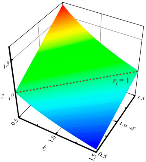
In Equation 8, i = 1, 2. When k1 to k3 take values in the range of [0.5, 1.5], the values of ri are shown in Figure 10.
As can be seen, the economic performance of the dual H-bridge integrated DCCB is comparable to that of the other two DCCBs that fully reuse the MB, and it will mainly depend on the values of k1 to k3. When the values of ki (i = 1, 2) are large and k3 is small, meaning the cost of the main components of LCS such as IGBT, UFD, and ADS is high, while the cost of diodes is low, the dual H-bridge integrated DCCB will have better economic performance compared to the other two DCCBs. The results of the economic analysis comparison are summarized in Table 3.
6 Simulation
Using the PSCAD/EMTDC electromagnetic transient simulation platform, the dual H-bridge integrated multiport DCCB is modeled within the offshore wind DC transmission system. The offshore wind DC transmission system is depicted in Figure 11.
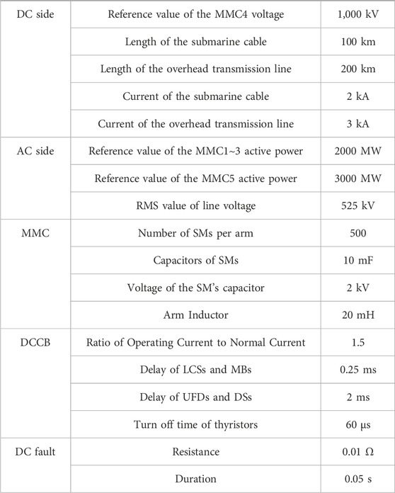
As illustrated in Figure 11, the offshore wind power DC transmission system includes 5 MMCs. MMC1 to MMC3 are the sending-end converters, each connected to a 100 km submarine cable, while MMC4 and MMC5 are the receiving-end converters, connected to a 200 km overhead transmission line. MMC4 employs constant DC voltage and reactive power control, with a set DC voltage reference of 1,000 kV. The remaining MMCs are configured for constant active power and reactive power control, with MMC1 to MMC3 having an active power reference of 2000 MW, and MMC5 set at 3000 MW. Dual H-bridge integrated five-port DCCBs are installed at both the positive and negative DC buses.
All DCCBs have consistent switching delays; the time required from the system sending the signal to the action of LCSs and MB is 0.25 ms, and the time required for UFD and DS to act is 2 ms. The simulation sets up line fault F1 and bus fault F2, with a fault grounding resistance of 0.01 Ω and a fault duration of 0.05 s. These parameters are summarized in Table 4.
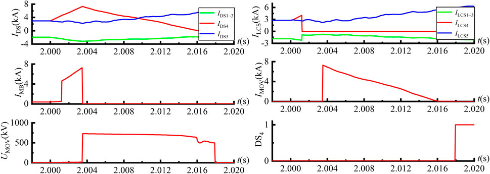
At t = 2 s, a pole-to-pole short circuit fault is introduced at the exit of line 4 in the dual H-bridge integrated five-port DCCB. The signal waveforms of the dual H-bridge integrated DCCB installed on the positive DC bus are shown in Figure 12.
From Figure 12, it can be observed that at t = 2 s, following the occurrence of the fault, the current flowing through the LCS4 rapidly increases. After a 1 ms fault detection delay, the system detects the fault and sends a trip signal to LCS4. Following a 0.25 ms delay for the LCS operation, LCS4 disconnects, causing the current ILCS4 through LCS4 to quickly drop to zero, at which point a trip signal is sent to the UFD4. After a 2 ms delay for the disconnector operation, UFD4 opens, relieving LCS4 from further stress. At this point, a trip signal is sent to the MB, and after a 0.25 ms delay for the MB operation, MB opens, and the MOV engages, causing the fault current to rapidly decrease to zero. At t = 2.0179 s, the disconnector DS4 trips, completely isolating the fault on DC line 4. Throughout the fault interuption operation, the fault current reaches its peak value of 7.30 kA when the MB operates.
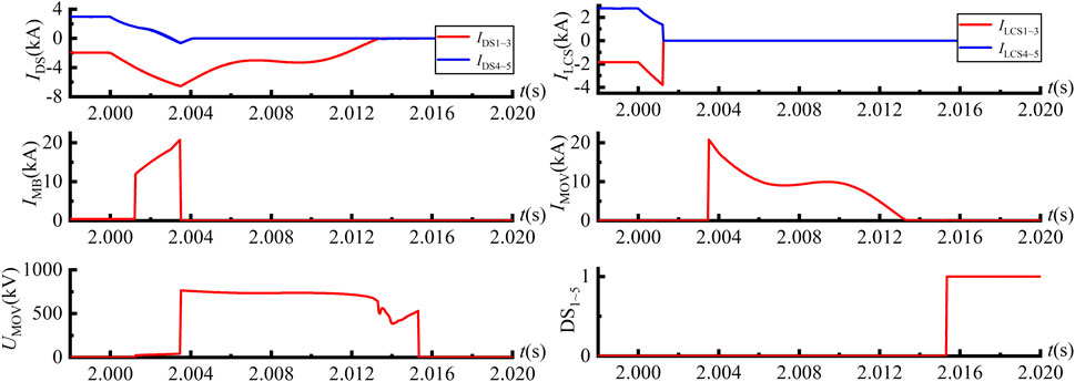
At t = 2 s, a pole-to-pole short-circuit fault is applied at the DC bus of the dual H-bridge integrated five-port DCCB, and the corresponding signal waveforms of the dual H-bridge integrated DCCB are shown in Figure 13.
From Figure 13, it can be observed that after the fault occurs at t = 2 s, the current through the LCS1 to LCS3 drops rapidly, while the current through the LCS4 and LCS5 rises sharply. After a 1 ms fault detection delay, the system detects the fault and sends a trip signal to LCS1 to LCS5. After a 0.25 ms delay in the operation of the LCS, LCS1 to LCS5 disconnect, and the current flowing through these LCSs, ILCS1 to ILCS5, rapidly drops to zero. At this point, a trip signal is sent to UFD1 to UFD5. After a 2 ms delay in the UFD operation, UFD1 to UFD5 disconnect, relieving LCS1 to LCS5 from voltage stress. A trip signal is then sent to theMB, and after a 0.25 ms delay in its operation, MB disconnects, and the MOV engages, causing the fault current to quickly drop to zero. At t = 2.0153 s, DS1 to DS5 trip, completely isolating the DC bus fault. During the entire DC fault interruption operation, the fault current peaks at 20.76 kA when theMB operates.
7 Conclusion
This paper proposes a dual H-bridge integrated multiport DCCB topology with bus fault clearing capability and its corresponding control strategy, and investigates its technical and economic performance. The five-terminal offshore wind power DC transmission system electromagnetic transient model was built and validated in PSCAD/EMTDC. The conclusions are as follows:
1. In terms of circuit topology design, the dual H-bridge integrated multiport DCCB introduces a first H-bridge group to achieve the reuse of the main breaker and metal oxide varistor, allowing the sole main breaker to interrupt bi-directional fault currents using only a series of unidirectional IGBTs. Additionally, the H-bridge component is further expanded with a pair of bridge arms connected to the DC bus, and a second H-bridge is formed in the load commutation switch using diodes, enabling the breaker to interrupt bus faults.
2. In terms of control strategy design, the dual H-bridge integrated multiport DCCB requires only 4 independent switching signals to interrupt line faults, consistent with the ABB DCCB. To interrupt bus faults, it only requires 3n + 1 independent switching signals, surpassing the ABB DCCB in terms of reliability and demonstrating superior technical performance.
3. Through economic analysis, it can be concluded that the dual H-bridge integrated multiport DCCB demonstrates superior economic performance due to the reuse of the main circuit breaker.
Data availability statement
The original contributions presented in the study are included in the article/Supplementary Material, further inquiries can be directed to the corresponding author.
Author contributions
HQ: Conceptualization, Writing–review and editing. ZP: Investigation, Writing–review and editing. YL: Data curation, Writing–review and editing. CZ: Methodology, Writing–review and editing. XQ: Supervision, Writing–review and editing. YH: Conceptualization, Writing–original draft.
Funding
The author(s) declare that financial support was received for the research, authorship, and/or publication of this article. This research was funded by the Guangxi Power Grid Company Science and Technology Program, grant number GXKJXM20222092.
Conflict of interest
Authors HQ, ZP, and YH were employed by Guangxi Power Grid Co., Ltd. YL, CZ, XQ were employed by the CSG.
The authors declare that this study received funding from Guangxi Power Grid Co., Ltd. The funder was involved in the study design, data collection, analysis, decision to publish, and preparation of the manuscript.
Generative AI statement
The author(s) declare that no Generative AI was used in the creation of this manuscript.
Publisher’s note
All claims expressed in this article are solely those of the authors and do not necessarily represent those of their affiliated organizations, or those of the publisher, the editors and the reviewers. Any product that may be evaluated in this article, or claim that may be made by its manufacturer, is not guaranteed or endorsed by the publisher.
Supplementary material
The Supplementary Material for this article can be found online at: https://www.frontiersin.org/articles/10.3389/fenrg.2024.1531266/full#supplementary-material
References
Abedrabbo, M., Leterme, W., and Van Hertem, D. (2020). Systematic approach to HVDC circuit breaker sizing. IEEE Trans. Power Del. 35 (1), 288–300. doi:10.1109/tpwrd.2019.2922253
An, T., Tang, G., and Wang, W. (2017). Research and application on multi-terminal and DC grids based on VSC-HVDC technology in China. High. Volt. 2 (1), 1–10. doi:10.1049/hve.2017.0010
Callavik, M., Blomberg, A., Häfner, J., and Jacobson, B. (2012). The hybrid HVDC breaker. ABB Grid Syst. Tech. Pap. 361, 143–152.
Corzine, K. A. (2017). A new-coupled-inductor circuit breaker for DC applications. IEEE Trans. Power Electron. 32 (2), 1411–1418. doi:10.1109/tpel.2016.2540930
Guo, Q., Zhang, J., and Chi, T. (2022). “Review of DC circuit breaker technology,” in 4th IEEE sustainable power and energy conference (ISPEC), curtin univ, ELECTR NETWORK, 2022. NEW YORK: Ieee, 1–5. doi:10.1109/ispec54162.2022.10033027
Hajian, M., Zhang, L., and Jovcic, D. (2015). “DC transmission grid with low speed protection using mechanical DC circuit breakers,” in General meeting of the IEEE-power-and-energy-society (NEW YORK: Ieee). Denver, CO, 2015.
Hassanpoor, A., Häfner, J., and Jacobson, B. (2015). Technical assessment of load commutation switch in hybrid HVDC breaker. IEEE Trans. Power Electron. 30 (10), 5393–5400. doi:10.1109/tpel.2014.2372815
Hedayati, M. H., and Jovcic, D. (2018). Reducing peak current and energy dissipation in hybrid HVDC CBs using disconnector voltage control. IEEE Trans. Power Del. 33 (4), 2030–2038. doi:10.1109/tpwrd.2018.2812713
Keshavarzi, D., Ghanbari, T., and Farjah, E. (2017). A Z-source-based bidirectional DC circuit breaker with fault current limitation and interruption capabilities. IEEE Trans. Power Electron. 32 (9), 6813–6822. doi:10.1109/tpel.2016.2624147
Kontos, E., Schultz, T., Mackay, L., Ramirez-Elizondo, L. M., Franck, C. M., and Bauer, P. (2018). Multiline breaker for HVdc applications. IEEE Trans. Power Del. 33 (3), 1469–1478. doi:10.1109/tpwrd.2017.2754649
Li, R., Xu, L., Holliday, D., Page, F., Finney, S. J., and Williams, B. W. (2016). Continuous operation of radial multiterminal HVDC systems under DC fault. IEEE Trans. Power Del. 31 (1), 351–361. doi:10.1109/tpwrd.2015.2471089
Li, S., Xu, J., Lu, Y., Zhao, C., Zhang, J., Jiang, C., et al. (2021). An auxiliary DC circuit breaker utilizing an augmented MMC. IEEE Trans. Power Del. 34 (2), 561–571. doi:10.1109/tpwrd.2019.2892445
Liu, F., Liu, W., Zha, X., Yang, H., and Feng, K. (2017a). Solid-state circuit breaker snubber design for transient overvoltage suppression at bus Fault Interruption in low-voltage DC microgrid. IEEE Trans. Power Electron. 32 (4), 3007–3021. doi:10.1109/tpel.2016.2574751
Liu, G., Xu, F., Xu, Z., Zhang, Z., and Tang, G. (2017b). Assembly HVDC breaker for HVDC grids with modular multilevel converters. IEEE Trans. Power Electron. 32 (2), 931–941. doi:10.1109/TPEL.2016.2540808
Majumder, R., Auddy, S., Berggren, B., Velotto, G., Barupati, P., and Jonsson, T. U. (2017). An alternative method to build DC switchyard with hybrid DC breaker for DC grid. IEEE Trans. Power Del. 32 (2), 713–722. doi:10.1109/tpwrd.2016.2582923
Mokhberdoran, A., Van Hertem, D., Silva, N., Leite, H., and Carvalho, A. (2018). Multiport hybrid HVDC circuit breaker. IEEE Trans. Ind. Electron. 65 (1), 309–320. doi:10.1109/tie.2017.2719608
Overstreet, A., Maqsood, A., and Corzine, K. (2014). “Modified Z-source DC circuit breaker topologies,” in Clemson-university power systems conference (PSC) (NEW YORK: Ieee). Clemson, SC, 2014.
Shi, Z., Zhang, Y., Jia, S., Song, X., Wang, L., and Chen, M. (2022). Design and numerical investigation of A HVDC vacuum switch based on artificial current zero. IEEE Trans. Dielectr. Electr. Insul. Artic. 22 (1), 135–141. doi:10.1109/tdei.2014.004533
Smeets, R. (2015). Safeguarding the supergrid. IEEE Spectr. 52 (12), 38–43. doi:10.1109/mspec.2015.7335799
Tang, G., Xu, Z., and Zhou, Y. (2014). Impacts of three MMC-HVDC configurations on AC system stability under DC line faults. IEEE Trans. Power Syst. 29 (6), 3030–3040. doi:10.1109/tpwrs.2014.2315666
Wen, W., Wang, Y., Li, B., Huang, Y., Li, R., and Wang, Q. (2018). Transient current interruption characteristics of a novel mechanical DC circuit breaker. IEEE Trans. Power Electron. 33 (11), 9424–9431. doi:10.1109/TPEL.2018.2797243
Xiao, H., Gan, H., Yang, P., Li, L., Li, D., Hao, Q., et al. (2023). Robust submodule fault management in modular multilevel converters with nearest level modulation for uninterrupted power transmission. IEEE Trans. Power Del. 39 (2), 931–946. doi:10.1109/tpwrd.2023.3343693
Xiao, H., Huang, X., Xu, F., Dai, L., Zhang, Y., Cai, Z., et al. (2022). Improved multiline HVDC circuit breakers with asymmetric conducting branches. Int. J. Electr. Power Energy Syst. 137, 107882. doi:10.1016/j.ijepes.2021.107882
Xiao, H., Gan, H., Huang, Y., and Z, C. A. I. (2024). Capacitor voltage ripple control strategy of lightweight modular multilevel converter for offshore wind power transmission. IEEE Trans. Ind. Appl. 60 (4), 5398–5406. doi:10.1109/tia.2024.3379112
Keywords: offshore wind power, multi-port, dc circuit breaker, H-bridge, DC fault
Citation: Qin H, Pan Z, Lu Y, Zou C, Qiao X and Huang Y (2025) Dual H-bridge integrated multiport DC circuit breaker for bus fault interruption in HVDC grids supporting large-scale renewable energy integration. Front. Energy Res. 12:1531266. doi: 10.3389/fenrg.2024.1531266
Received: 20 November 2024; Accepted: 16 December 2024;
Published: 07 January 2025.
Edited by:
Yuqing Dong, The University of Tennessee, United StatesReviewed by:
Huangqing Xiao, South China University of Technology, ChinaJie Liu, Hunan University of Technology, China
Copyright © 2025 Qin, Pan, Lu, Zou, Qiao and Huang. This is an open-access article distributed under the terms of the Creative Commons Attribution License (CC BY). The use, distribution or reproduction in other forums is permitted, provided the original author(s) and the copyright owner(s) are credited and that the original publication in this journal is cited, in accordance with accepted academic practice. No use, distribution or reproduction is permitted which does not comply with these terms.
*Correspondence: Zhen Pan, NDU3MzI0MTE4QHFxLmNvbQ==
 Hui Qin1
 Yunfeng Huang