- Zaozhuang Power Supply Company, State Grid Shandong Electric Power Company, Zaozhuang, Shandong, China
Multiple microgrid (MG) distribution systems are facing challenges owing to variations in the operational statuses of the individual MGs, which experience voltage and current fluctuations during transient interconnections. The impedances of the interconnecting lines further exacerbate the unevenness of power distribution among the MGs, hence threatening the operational stability of the system. To achieve flexible and seamless interconnections between multiple MGs, we fully analyzed the interconnected structures and operation modes of the MGs; then, we designed a transient switching control method based on investigation of the transient interconnection processes to ensure smooth transition of the MGs. Additionally, to balance the power distribution among the interconnected MGs, a voltage–current-based coordinated power control strategy was synthesized using advanced synchronized fixed-frequency technology. Simulation case studies were conducted, and the results indicate that the proposed coordinated power control scheme effectively facilitated instantaneous interconnections between the isolated regions, thereby avoiding voltage disturbances and current surges. Furthermore, it efficiently equalized and distributed the output power from the distributed energy sources, thereby enhancing the operational flexibilities and stabilities of the MGs and distribution system.
1 Introduction
With the rapid development of renewable energy technologies and in-depth promotion of smart-grid construction, microgrids (MGs) have emerged as crucial forms of distributed energy integration as well as effective means to address energy supply challenges, improve energy utilization efficiency, and promote the consumption of renewable energies (Zhao et al., 2022). However, in a distribution network (DN) system comprising multiple MGs, the varying independent operating state of each MG often leads to transient voltage and current fluctuations during interconnection. These fluctuations not only compromise the power quality but also jeopardize the safe and stable operation of the entire system. Furthermore, the presence of link impedances often result in uneven power distribution among the MGs, further exacerbating system instability (Sun et al., 2023; Wang et al., 2024). Consequently, research into transient switching and coordinated power control strategies for achieving flexible interconnections of multiple MGs is of paramount importance for realizing stable interconnections and optimal power distribution among the MGs, thereby improving system operational performance.
Presently, the mainstream control methods for the inverters in the MGs mainly include the P/Q, V/f, and droop control strategies (Heins et al., 2023; Alzayed et al., 2022; Afshari et al., 2024). Fan et al. (2022) enhanced the droop control mode to transform the droop coefficients into data that can be mediated online; this improved the power distribution accuracy among the inverters and inhibited commutation. Cheng et al. (2024) presented a control algorithm based on the virtual synchronous generator (VSG), where the Q-U sag control method was improved based on a proportional–integral controller; this improved the voltage regulation performance and guaranteed the accuracy of the system power distribution. Zong et al. (2023) introduced impedances into MGs implementing the traditional sagging control strategy; here, the key system parameters were modified using a variable control method to observe their influences on the operational stability of the system. Feng and Liu (2023) identified a single steady-state operating point in an MG, built a small-signal model, analyzed its root trajectory, and finally obtained the approximate range of the optimal value. Vaishnav et al. (2023) built a small-signal model of the inverter droop control module in an MG and obtained appropriate control coefficients based on the trend of its root trajectory. Li et al. (2018) improved the traditional droop control approach and introduced a power differential term based on the droop control; here, the authors analyzed and evaluated the small-signal model to determine the influences of the droop coefficient and power differential term on system stability. The abovementioned works contributed notably to the development of control methods for MG systems. However, in multiple-MG interconnection systems, these methods often struggle to account for the distinct independent operational characteristics of each of the MGs and the transient stability during the interconnection process. Thus, challenges remain in optimizing the control methods to ensure seamless transient switching between MGs.
In recent years, research on the interconnection modes of multiple MG systems has mainly included the AC, AC–DC hybrid, and flexible DC interconnections (Wang et al., 2022). For AC interconnections, Chen et al. (2024) constructed an island multi-MG system with multiple parallel points to realize seamless transition between joint grid-connected and off-grid operations as well as separate grid-connected and off-grid operations. In Yang et al. (2024), the main controller as well as the controller of each MG were adopted in a multi-MG interconnection system to realize controllable AC interconnection for monitoring the operational status of the system. Fattaheian-Dehkordi et al. (2022) proposed an event-based consistency control method for the AC–DC hybrid multi-MG system to effectively solve its power distribution issue. Mo et al. (2021) connected DC/AC converters with the AC/DC buses in each of the sub-MG systems to achieve flexible interconnections. Xie et al. (2024) employed a power router for the single-port flexible DC interconnections in a multi-MG system to realize multidirectional flow of the heavy energy and active power control of the system. Yang et al. (2023) presented an electrical power router comprising multiple converter ports and an energy pool to realize single-port DC interconnection and power balance among the multiple MGs. Joshi et al. (2022) used a voltage-source-type converter to connect multiple MGs to a common DC bus to realize multiport DC interconnection. In Zhao et al. (2024) and Li et al. (2022), the photovoltaic (PV) system and energy storage systems (ESSs) were integrated with a common DC bus, respectively, through which the power was balanced effectively to guarantee reliable operation of the multi-MG system. As detailed above, the different interconnection modes have their individual application scenarios and limitations. Although several outcomes have been achieved for multi-MG systems, theoretical and experimental studies are still needed to select appropriate interconnection modes for balancing the power distribution between the MGs to ensure system stability after interconnection.
Liu et al. (2024) focused on power distribution as well as coordinated control in a multi-MG system and proposed a coordinated control strategy with automatic load power distribution based on the maximum power and state of charge of the ESS, along with verifying its roles in independent DC MGs under different working mode settings. Dhar et al. (2022) proposed a method to divide the power layers according to the net load of the system and charging/discharging powers of the batteries; they proposed a coordinated control strategy based on the power layers while ensuring the voltage stabilities of PV DC MGs under different operating conditions. Nahata et al. (2021) proposed a hierarchical coordinated control strategy to address the power imbalances in DC MGs; by setting three different layers of control content, this method achieved economical and reliable operations of the MGs. Li et al. (2024) introduced a fuzzy logic controller for the DC MG system encompassing electric–hydrogen energy storage to reduce the losses of lithium batteries by setting control methods with different interface converters. Bharatee et al. (2024) proposed a coordinated control strategy involving voltage and power based on the state balance of energy storage, and this approach effectively improved the voltage stability and power distribution balance in a dual-bus MG. Gu et al. (2024) combined the fuzzy and droop control theories to effectively adjust the power and improve the robustness of the MG. The above strategies are pivotal for ensuring optimal functioning of the MGs. Nevertheless, these methodologies predominantly concentrate on maintaining the power balance and stability within individual MGs, leaving ample scope for advancements in the field of coordinated power control within interconnected multi-MG systems.
Zhu et al. (2023) introduced a power mutual-aid autonomous control strategy using solid-state transformers to enhance the system stability and improve fault tolerance within an interconnected multi-MG system. This strategy enables MGs with minor imbalances to provide power support to those with significant imbalances, thereby minimizing the degree of imbalance across all MGs while achieving power balance and autonomous distribution. Li et al. (2019) proposed a flexible control method for AC/DC microgrid clusters; this approach utilizes interconnection power increments to obtain the actual transmission power reference values through DC–DC and DC–AC interconnection devices while ensuring that each MG operates according to these reference values for effective power coordination control among the interconnected MGs. Yoo et al. (2020) reported a distributed coordinated control strategy that initially adjusts the power output of each MG using droop control based on a consensus algorithm; then, this strategy achieves power sharing among the interconnected MGs through normalization of the interconnection converters. Zhou et al. (2018) employed a set of interconnection converters to link various MGs, where each converter was connected based on a distributed consensus mechanism.
Despite the large contributions of these works, several key challenges persist, such as ensuring seamless transitions during the interconnection of MGs, achieving flexible power distribution, and maintaining operational stability in a complex interconnected environment. Within such systems, in-depth research on flexible power distribution and coordinated control strategies among the different MGs is crucial for optimizing the operational performance of the entire DN system. Accordingly, to improve the flexibilities and stabilities of the MGs as well as upper DN, we present a transient switching method and coordinated power control strategy for optimal operation and flexible interconnection of a multi-MG DN. Specifically, the interconnection architecture and operational modalities of the multiple MGs are first discussed, and a transient switching control approach is subsequently proposed to ensure seamless transitions within interconnected multi-MG systems. Then, to address the challenge of power distribution among the MGs in the interconnected environment, a voltage–current power coordination droop control strategy is proposed along with the synchronous fixed-frequency technology, which guarantees flexible power distribution and operational stabilities of the MGs. Finally, simulations are conducted to validate the efficacies and superiorities of the proposed methodologies.
2 Interconnection structure and operation modes of the multi-MG system
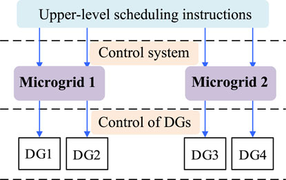
The operational control of the interconnected MG system involves a decentralized approach, as depicted in Figure 1; this strategy aims to foster independence and autonomy within each MG while minimizing reliance on the communication system. At the upper layer, the control is limited to issuing interconnection scheduling commands and sharing voltage bus information across different MGs via low-bandwidth communication channels. On the other hand, the independent MG control layer oversees power coordination both among and within the MGs. Within each MG, the distributed generation (DG) components typically employ synchronous constant-frequency voltage–current droop control to enable swift and seamless voltage and current adjustments, thereby enhancing the overall responsiveness and stability of the interconnected system.
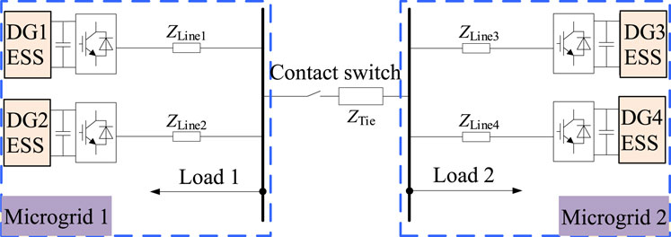
Figure 2 shows the regional structure studied in this work considering two MGs (MG1 and MG2) as examples. The two MGs have identical structures and comprise two ESSs and loads each, which are connected to the AC bus through their respective line impedances. In this case, the control algorithm and communication protocol can be designed in a unified manner while reducing the complexity of the control system and improving the response speed as well as coordination ability. The bus bars of MG1 and MG2 are connected through the contact switch, and the two MGs can switch between independent and interconnected operations through the opening and closing of the contact switch. To facilitate analysis, we simulated the output variations and normal load fluctuations of PV and wind power units by dynamically adjusting the load sizes. The ESSs are mainly used to balance the system power and maintain the common bus voltage. When the power fluctuates, the common bus also responds accordingly, and the energy storage unit adopts a synchronous fixed-frequency U-I droop control strategy. Thus, when the power of the AC or DC subnet is insufficient or excessive, the AC frequency or DC voltage will correspondingly reduce or increase; that is, the AC frequency or DC voltage can represent the power changes inside the AC or DC grid, and the common bus voltage can contribute to changes in the MG’s power. Therefore, the power of the AC subnet and DC network can be regulated by adjusting the corresponding AC frequency and DC voltage.
The specific switching process of the MG interconnection strategy can be categorized into five distinct operating stages as follows:
1) Independent operation: Upon receiving the disconnection command for the interconnection switch or prior to the closure command, the interconnection switch remains in the disconnected state, and the MG operates independently. During this stage, improved droop control is implemented based on virtual negative impedance compensation, as proposed in Section 4.
2) Phase tracking: Initially, the two MGs operate independently. To mitigate any power distribution imbalances, the virtual negative impedance is introduced. However, this adjustment alters the q-axis voltage reference value, resulting in a phase offset between the inverter output voltage and synchronous reference phase. Consequently, a phase tracking process is incorporated. Upon receiving the instruction, the interconnection switch is closed once the synchronization reference phase tracking is completed, thus transitioning to the basic U-I droop control strategy.
3) Interconnection operation: At this stage, the interconnection switch is closed to connect the two MGs. To further address the power distribution imbalances, the virtual negative impedance compensation is reintroduced for the line impedances, enabling uniform power distribution within the two MGs; this allows switching to the improved droop control strategy based on virtual negative impedance compensation.
4) Coordinated control: During the operation of the interconnected MGs, the impedance of the interconnection line can lead to unbalanced power distribution between the two MGs. To enhance the accuracy of power distribution within the interconnected MGs, a voltage adjustment control strategy is integrated. This strategy aims to achieve uniform power distribution across the interconnected grid by equalizing the power between the two MGs.
3 Flexible interconnection control strategy for the multi-MG system
3.1 Transient switching analysis
The voltage control converter comprises a double-loop controller for the voltage and current. Because of coupling effects between the control loops, the transient characteristics of the converter represent the response behaviors of higher-order systems, which can be challenging to model and solve accurately owing to their complexities. For the voltage-controlled converter, the goal is to control the port voltage while the external characteristic is the voltage source. To simplify the analysis, the converter is considered to be equivalent to an ideal voltage source, and an equivalent circuit is established as shown in Figure 4. Figure 3A presents the interconnected operational state of the two MGs, where U1 is the output voltage of the inverter in MG1, iload1 is the output current of the inverter in MG1, and Uload is the load voltage. Figure 3B shows the two MGs in the independent operation mode.
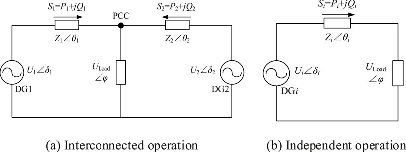
Figure 3. Equivalent circuits for transient switching of the interconnected microgrids: (A) interconnected operation; (B) independent operation.
As the two MGs operate independently, their load characteristics, sizes, and disturbances will lead to differences in their operating states that then manifest in the phase, frequency, voltage, and current at the common connection point. In the transient switching process of a regional interconnection without intervention and control, there may be large voltage and current shocks inside the MGs that may cause the internal inverters to go off-grid and even collapse of the system. Therefore, it is necessary to analyze the transient switching process and adopt control strategies to reduce the voltage and current impacts to ensure uninterrupted operation of the inverters and loads.
The output voltage and current of an inverter have three characteristics, i.e., amplitude, phase, and frequency. To reduce the impacts of voltage and current during interconnection, the transient voltage and current changes during interconnection are analyzed.
where upcc1 and upcc2 are the respective voltages of MG1 and MG2 at the common connection point; uv1 and uv2 are the respective voltages of MG1 and MG2; ω1 and φ1 are the respective voltage angular frequency and voltage phase angle of MG1; ω2 and φ2 are the respective voltage angular frequency and voltage phase angle of MG2. To analyze the influences of the three factors, the control variable method is employed.
3.1.1 Amplitude as the variable
The phases and frequencies of the voltages and currents of the two MGs are coincident such that
3.1.2 Frequency as the variable
The phases and amplitudes of the voltages and currents of the two MGs are coincident such that
3.1.3 Phase as the variable
The amplitudes and frequencies of the voltages and currents of the two MGs are coincident such that
From Equations 2–7, it is seen that the voltage and current impacts on the transient interconnection process are mainly influenced by the phase offset. Meanwhile, to eliminate the influence of variable frequency on the transient interconnection process, the two MGs utilize the U-I droop control method based on the advanced synchronous fixed-frequency technology and provide unified frequency support for the global inverter through satellite synchronization so that the inverter frequency is fixed at 50 Hz; this eliminates the influence of the frequency offset on the interconnection transient switching process and reduces the impacts of voltage and current. On the other hand, the voltage and current amplitudes mainly depend on the load size, and the load demands in the MGs are different, leading to load differences. Considering the uncertainties in load demands, it is impossible to improve the control strategy. The effects of phase on voltage and current shocks can be discussed in terms of the following two cases.
1) When the line impedances of the MG inverters are identical and synchronous fixed frequency control is used, the phase angles of the inverter output voltages are φu1 = φu2 = φu3 = φu4. Moreover, as the line impedances are consistent, the phase angles of the currents are φi1 = φi2 = φi3 = φi4. Hence, the voltage and current phase angles of both MGs at the common connection point are identical, that is, φpcc1 = φpcc2 = φpcc3 = φpcc4. At this time, when the two MGs are flexibly interconnected through the contact switch, the voltage and current shocks can be obtained as Equation 8, 9, respectively.
Under this condition, the voltage impulse is completely based on the voltage amplitude difference at the common connection point. The influences of the frequency and phase on the transient voltage and current impulses are eliminated. Thus, the transient voltage shock during interconnection of the MGs is greatly reduced.
2) When the line impedances of the MG inverters are different, the output voltage and current phase angles are different, that is, φu1 ≠ φu2 ≠ φu3 ≠ φu4 and φi1 ≠ φi2 ≠ φi3 ≠ φi4. Therefore, the voltage and current phase angles of both MGs at the common connection point are also different, that is, φpcc1 ≠ φpcc2 ≠ φpcc3 ≠ φpcc4. The virtual negative impedance control strategy presented later can be used to compensate for the line impedance. As shown in Equation 10, the equivalent output impedances of the inverters of both MGs can be made consistent so that they can be considered the inverter impedances.
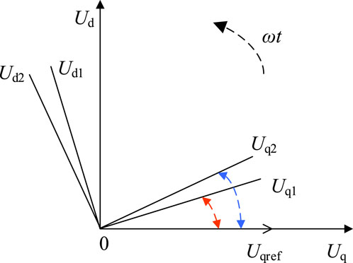
Thus, regardless of the inverter line impedances, when the synchronous fixed-frequency U-I droop control strategy is implemented, the voltage and current impacts on the transient switching process of the regional interconnection caused by differences in the phases and frequencies of the voltages and currents can be reduced. Smooth transition of the operating state is also guaranteed along with improved flexibility of the inverter. The U-I droop control realizes tracking of the inverter output voltage phase consistency while fixing the q-axis voltage reference value Uqref to 0. To improve the uneven power distribution, a virtual negative impedance is introduced, which not only changes the q-axis voltage reference value but also causes the inverter output voltage phase to shift relative to the synchronous reference phase, as shown in Figure 4.
3.2 Coordinated power control method
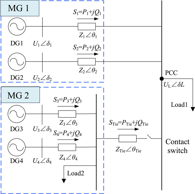
In this approach, the U-I droop control with synchronous fixed frequency is utilized; this strategy is suitable for MGs or DG systems, particularly in the off-grid mode. It achieves voltage stability, frequency synchronization, and load power sharing through adjustment of the relationships between the voltages and currents. As the frequency is fixed at 50 Hz, the AC bus voltage frequency cannot reflect the power changes in the MG. To solve this problem, coordinated power control between the two interconnected regional MGs is realized by adjusting the bus voltages of the MGs. The model for the power distribution between the MGs is shown in Figure 5.
To avoid conflicts during coordinated power control between the MGs, the voltage correction adjustment method is used to coordinate the power distribution, and the improved droop control with virtual negative impedance ensures that the power within each MG is distributed equally; further, the power within the entire interconnected MG system is distributed equally. Specifically, in the case of multiple MGs, the improved droop control utilizes the virtual negative impedance to compensate for the tie-line impedance, thereby eliminating the tie-line voltage drop between the MGs. In the absence of a tie-line impedance voltage drop, the output voltage and current of each MG remain consistent, resulting in equal active and reactive power outputs from each MG and ultimately ensuring even power distribution. Similarly, within a standalone MG, the improved droop control uses the virtual negative impedance to compensate for the line impedance, thus ensuring uniform power distribution among the PV, wind, and other power generation units within the MG. The optimized control is as shown in Figure 6; here, Figure 6A illustrates the traditional droop control method to simulate the behavior of a synchronous generator to enable power control in the parallel converters, and Figure 6B shows the droop control method with added voltage correction that introduces a voltage compensation link to the traditional droop control of the inverter. This link corrects the droop control voltage reference value of the inverter, mitigating the impacts of the line impedance voltage drops and enhancing the accuracy of power distribution in the interconnected MGs.
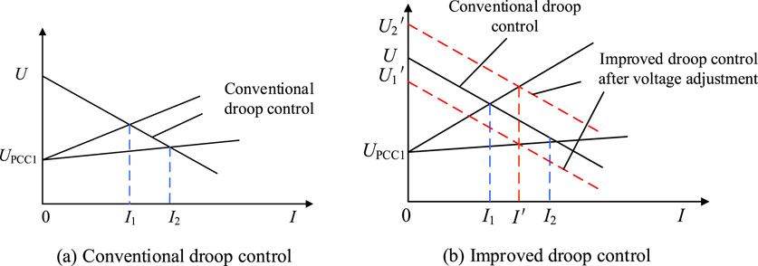
Figure 6. Schematics for voltage adjustment control: (A) conventional droop control; (B) improved droop control.
For MG1, the droop characteristic equations of DG1 and DG2 are related to the voltage at the common connection point:
where Uo1 and Uo2 are the output voltages of MG1 and MG2, respectively; ∆ULine1 and ∆ULine2 are the line voltage drops of MG1 and MG2, respectively; UPCC is the voltage at the common connection point; ∆UTie is the voltage drop of the tie-line impedance.
When the differential voltage drop of the tie-line impedance ∆UTie = 0, both MGs output the same voltages and currents such that their output active and reactive powers are identical. Combining Figure 7 with Equations 11, 12, it is seen that when ∆UTie ≠ 0, there is a difference in the output voltages of the sub-MGs, which results in imbalances in the distribution of the output active and reactive powers. Substituting for droop control in Equations 11, 12 yields
To improve the power distribution accuracy in the interconnected MGs, i.e., to eliminate the effects of the tie-line impedance voltage drops, MG2 is subjected to voltage regulation as shown in Equation 15:
where U* is the droop control reference value.
The output voltage is compensated by feeding back the tie-line impedance voltage drop to the droop control equation, thus eliminating the effect of the line impedance voltage drop, improving the precision of power allocation within the interconnected MGs, and realizing power allocation when ∆UTie = 0.
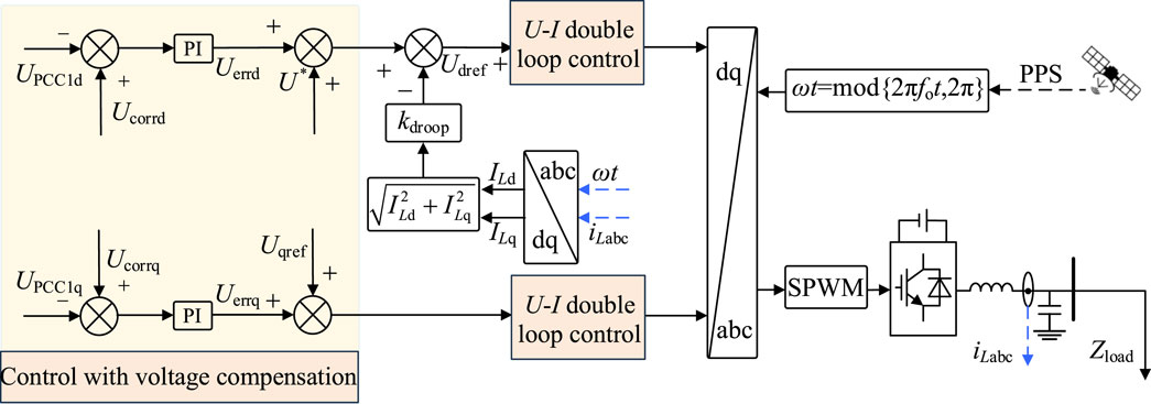
The final control strategy is shown in Figure 7, where a voltage compensation link is added to the sag control of the inverter to correct its voltage reference value; this eliminates the influence of the line impedance voltage drop and improves the accuracy of power allocation within the interconnected MG system.
In Figure 7, Ucorr is the reference voltage after voltage compensation and Uerr is the deviation between the AC bus voltages of the two MGs that is added to the voltage adjustment signals of the droop controls of the two MGs after d-q transformation to recover the AC bus voltages using Equations 19, 20. These voltages satisfy the following relations:
The inverter collects the AC voltages from the two buses at the ends, calculates the amplitude references for voltage compensation using the root mean-squared (RMS) values, and derives the amplitude reference values as shown in Equation 18. The regulation of the contact line current is dependent on the voltage difference between the two AC buses. After correcting the voltage deviations, reasonable power distribution between the two interconnected MGs can be achieved to ensure reliable and stable operation of the system.
4 Mode-switching control strategy of the multi-MG system
4.1 Phase tracking
The islanding state was identified using the determination algorithm in Feng and Liu (2023); accordingly, if the DG output current phase is instantaneously switched from the distribution grid phase to the pulse-per-second (1PPS) synchronous reference phase, the inverter current experiences a significant impact that can potentially even trigger overcurrent protection. To mitigate this current impact, the frequency of the DG output current should be gradually adjusted to track the 1PPS synchronous reference phase until they are aligned.
A tracking differentiator (TD) can provide an overshoot-free tracking process for a system by adjusting only one acceleration-limiting parameter; further, it satisfies the property that smaller system inputs can elicit faster adjustment times. If the DG output phase is θ(t), angular velocity is ω(t), and angular acceleration is α[θ(t), ω(t)], then the second-order series-type integrator system is given by
The fast optimal integrated control function that converges to the origin is given by
Substituting θ(t) from Equation 22 with θ(t)- θ1PPS(t) into Equation 21 gives
The output current phase θ(t) tracks the 1PPS synchronized reference phase θ1PPS(t) under the angular acceleration limit of αmax, and larger values of αmax allow faster tracking. Considering the system control as being discrete, the discretized angular acceleration is given by α(k) = fhan[(α(k)-α1PPS(k))/ω(k)αmax(k)h], where θ(k) and ω(k) are the output phase and angular velocity of the inverter, respectively. θ1PPS(k) is the 1PPS synchronization reference phase, αmax the angular acceleration limit, and h is the iteration step size. For fsg(x,d) = (sign(x + d)-sign(x-d))/2, the iterative process shaped as u = fhan(x1,x2,r,h) is given by
Equation 24 can then be discretized as
When the frequency does not vary significantly, the phase can be approximated as a ramp function. However, Equation 25 is tailored for a second-order system and inherently exhibits a steady-state error in tracking the ramp function. To enhance the phase-tracking performance, the phase-tracking system requires an upgrade or adjustment rather than being downgraded.
As shown in Figure 8, noting that fh is the output of the fast optimal synthesis control function, Δθ(k) is the difference between the DG output current phase θ(k) and the synchronization reference phase θ1PPS, Δω(k) is the angular velocity increment, and Δθref = 0 is the phase difference input. By replacing θ(k), ω(k), and θ1PPS(k) in Equation 25, the phase-tracking process can be downgraded to
Compared with Equation 25, the process in Equation 26 changes from tracking the phase reference θ1PPS(k) to the phase difference reference Δθref, and the system is downgraded from a tracking ramp function to a tracking step function. Taking αmax = 0.3 and iteration frequency 15 kHz as example values, the DG output current angular velocity is obtained according to the value of k. The initial value of the difference between the inverter current output phase and 1PPS synchronization reference phase is θ0. The theoretical calculations are shown in Figure 9. The range of values for θ0 is [0,2); in the limiting case when θ0 = 2, the maximum value of the inverter angular velocity increment k is −1.37 rad/s, converted current output frequency is approximately 49.8 Hz, and phase tracking is continuous without overshoots, therefore meeting the grid demand. It can be seen from Figure 9 that as the initial phase difference changes, both the angular velocity increment and phase difference remain stable without overshoots. Eventually, regardless of their initial values, both these parameters converge to 0. This confirms that the TD-based phase tracking method ensures continuous, non-overshooting phase and frequency adjustments that are aligned well with the load frequency demands.

Figure 9. TD-based results: (A) TD-based phase tracking process; (B) TD-based frequency increment process.
4.2 Dual-mode flexible switching strategy for grid-connected/islanded operations
4.2.1 Switching control strategy from grid-connected to autonomous operation
As shown in Figure 10, the distributed power supply in the MGs generally works in the P-Q controller mode for grid-connected MGs. As seen from the right diagram of Figure 10, under normal steady state, each DG system maintains the output d-axis current synchronous with the grid voltage through power and current double-closed-loop control. To achieve flexible switching from grid-connected to autonomous operation, the satellite timing signal current control is adopted. The inverter controller not only calculates the phase-locked loop output angle θpll but also derives the synchronization angle θ using the satellite timing signal.
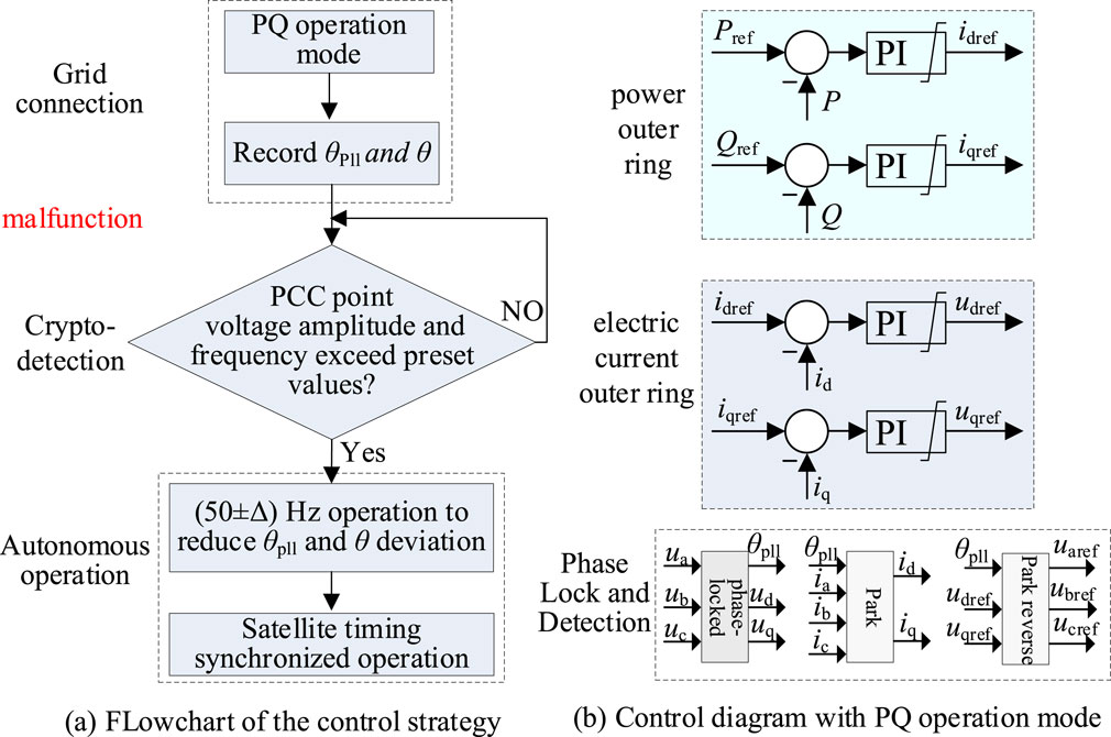
Figure 10. Switching control strategy from grid-connected to autonomous operation: (A) flowchart of the control strategy; (B) control diagram under the P-Q operation mode.
Considering the uncertainty of fault occurrence, the controller continuously monitors the voltage magnitude and frequency at the grid point in real time. At the instant of unplanned islanding, the voltage and frequency at the grid point change correspondingly owing to the loss of the clamping effect from the grid voltage and subsequent alterations in the internal power distribution of the system. To minimize blind spots during detection, especially under unity-power-factor conditions, a small amount of reactive current (e.g., 0.1 p.u.) can be injected by the inverter during normal operation. This exploits the asymmetry between the inverter’s output power and load after islanding to expedite the voltage and frequency variations. When the detected voltage amplitude falls below 70% of its rated value or the frequency exceeds a preset threshold, it is deemed that islanding has occurred, which prompts switching to autonomous operation control. Simultaneously, the phase-locking angle at this moment, denoted as θpll0, is saved for future reference.
There may be a significant deviation between the voltage synchronization angle during grid-connected operation and that provided by the satellite timing, necessitating flexible adjustment of the load current phase. To address this, the inverter output current phase is controlled to align with θpll0, which is based on the deviation between θpll0 and θ detected during transition from grid-connected to autonomous operation. Specifically, if the difference between θpll0 and θ is within the interval [10°, 180°], the inverter output current frequency increases to 50.3 Hz. Conversely, if the difference is within (−180°, −10°], the frequency is adjusted to 49.7 Hz. When the phase difference between the captured grid-connected voltage angle and satellite timing synchronization angle is within the narrow range of (−10°, 10°), the inverter output current frequency is set to 50 Hz, and the A-phase current crossing point is synchronized with the rising edge of the 1PPS signal to ensure precise phase alignment.
4.2.2 Switching control strategy from autonomous to grid-connected operation
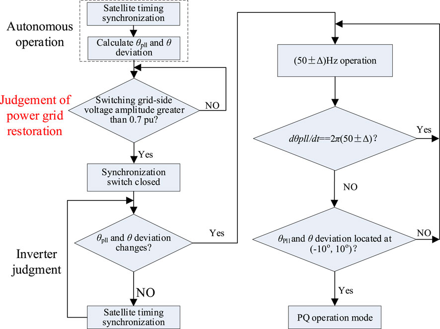
Since the area of the distribution station operates in the current-source mode based on satellite timing synchronization, when the grid voltage is restored and grid-connected switch of the station area is closed, the output current of each inverter within the station area remains approximately unchanged. Consequently, this arrangement mitigates the risk of significant transient current stress issues. Given the above analysis, the control flowchart from autonomous to grid-connected operation is as shown in Figure 11.
As depicted in Figure 11, during autonomous operation of the MG, the output current is synchronized with the satellite timing signal; simultaneously, the controller calculates both the grid-side voltage phase θpll and satellite timing synchronization angle θ, which should ideally match the load impedance angle. When the synchronization switch detects that the amplitude of the grid-side voltage exceeds 0.7 p.u., it closes and causes the voltage at the grid-side point to shift from θpll to θ owing to the influence of the grid voltage clamp. Upon detecting this change, the inverter adjusts the output current frequencies of all inverters to either 50.3 Hz or 49.7 Hz and evaluates the changes in θpll based on the adjusted frequencies. If the grid-connected operation results in a phase voltage detection rate change that is not aligned with the inverter output current frequency, the deviation between θpll and θ will vary. When this deviation is within (−10°, 10°), the operation modes of the inverters transition to the P-Q mode, as illustrated in the control block diagram in Figure 10B.
5 Case studies
To verify the effectiveness of the grid-connected/autonomous operation state switching between two isolated MGs under the proposed method, simulations were conducted. The load for the regional MG1 was set to 2 kW of active power and 2 kVar of reactive power, whereas the load for the regional MG2 was set to 10 kW of active power and 10 kVar of reactive power. The total simulation time was 0.2 s, and the specific simulation procedures of the system are as follows:
1) From 0 to 0.05 s, the two isolated MGs operate independently. Owing to the smaller load of MG1 than MG2, its corresponding output current is smaller such that I1 = 6.42 A and I2 = 29.72 A. After droop control, the output voltage of MG1 is slightly higher than that of MG2, where U1 = 324.67 V and U2 = 303.97 V.
2) From 0.05 s to 0.15 s, the interconnect switch is closed and opened sequentially to observe the transient switching effect.
Figure 12 shows the results of transient switching of the voltages and currents of the MGs. Under the proposed control strategy with a synchronous fixed frequency, the voltage does not differ significantly (U1 = 315.91 V, U2 = 311.14 V) while the current enters steady state after a small perturbation (I1 = 15.38 A, I2 = 21.31 A). Moreover, there are no voltage and current impacts during the transient switching process. The simulation results demonstrate that under the proposed control strategy, transient interconnection between different isolated MGs can be achieved smoothly without voltage perturbations or current shocks, thereby enhancing the flexibility of MG operation.
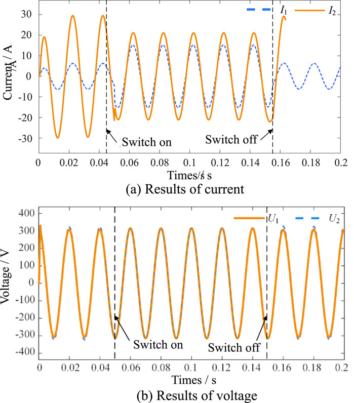
Figure 12. Simulation results of the transiently switched (A) currents and (B) voltages of the microgrids.
After voltage the adjustments, the simulation results are as shown in Figures 13, 14.
1) From 0 to 0.05 s during which the interconnection switch is disconnected, both MGs operate in isolation. As depicted in Figure 13, when the conventional control strategy prior to improvement is employed, the active power fluctuation of DG1 and DG2 upon connection to the system reaches an amplitude of 4.69 kW within 0.41 s, while the reactive power fluctuation attains an amplitude of 4.05 kVar in 0.49 s. In the steady state, these DG systems maintain an active power of 4 kW and a reactive power of 4 kVar. Similarly, the active power fluctuation of DG3 and DG4 reaches an amplitude of 1.15 kW at 0.41 s, while the reactive power fluctuation amplitude is 1.03 kVar at 0.49 s, before stabilizing at 1 kW and 1 kVar, respectively. As evident from Figure 14, during the period of 0–0.5 s, when the improved synchronous fixed-frequency control strategy is utilized, the power distribution curves of the four DG systems resemble those observed before the improvement, albeit with potential improvements in the transient behavior and stability.
2) When the interconnection switch is closed between 0.05 and 0.15 s, the output powers of the four DG systems within the interconnected MGs can be distributed equally. The voltage adjustment compensates for the tie-line impedance voltage drop, enhancing the precision of power distribution. At the moment of closure at 0.05 s, a brief transient process occurs, resulting in a decrease in the power supplied by DG1 and DG2 and an increase in the power supplied by DG3 and DG4 after stabilization, as shown in Figures 13, 14.
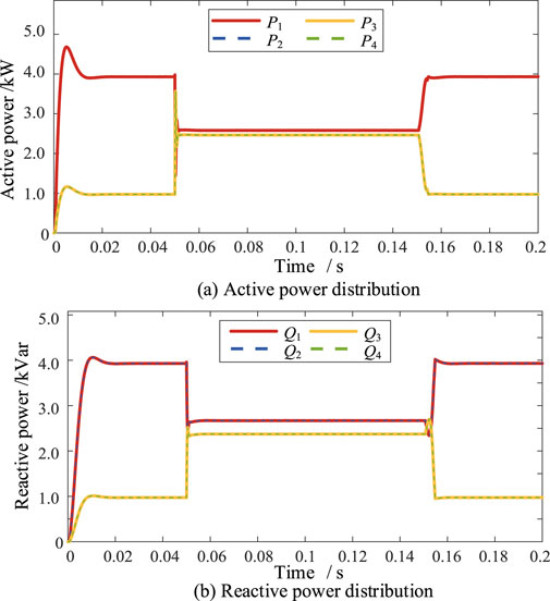
Figure 13. Simulation results for (A) active and (B) reactive power distributions before improvement.
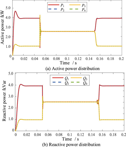
Figure 14. Simulation results for (A) active and (B) reactive power distributions using the improved control strategy.
Under the conventional control strategy, the active powers of DG1 and DG2 decrease rapidly to 1.41 kW while the reactive powers decrease to 2.13 kVar; similarly, the active powers of DG3 and DG4 increase rapidly to 3.68 kW while the reactive powers increase to 2.62 kVar. In contrast, under the improved synchronized fixed-frequency control strategy, the power fluctuation during the transition is more pronounced, with the active powers of DG1 and DG2 decreasing to 0.88 kW and the reactive powers to 1.93 kVar, while the active powers of DG3 and DG4 jump from 1 kW to 4.24 kW and the reactive powers increase from 1 kW to 2.99 kVar.
Owing to the presence of the interconnection device, the output power is quickly and evenly distributed after the transient state. From Figures 13, 14, although the power supply during the interconnection period is smooth both before and after the improvement, it is not possible to equally distribute the supplied power with the conventional control strategy. Specifically, DG1 and DG2 distribute 0.08 kW more active power and 0.23 kVar more reactive power than DG3 and DG4. However, after adopting the synchronized fixed-frequency control strategy, the four DG systems redistribute the power following the transient period and transition to a new steady state, enabling even distribution of the supplied power.
6 Conclusion
This work proposes a transient switching control method and a voltage-current-based coordinated power control strategy to achieve flexible interconnection and balanced power distribution among multiple MGs, enhancing their operational stability and flexibility. Simulation studies were conducted to verify the effectiveness and superiority of the proposed approaches.
1) Integrating multiple MGs into a distribution system increases the overall operational cost while markedly diminishing the system operating losses and voltage fluctuations, thereby fostering a harmonious balance between economic feasibility, environmental sustainability, and operational stability of the DN.
2) The implementation of a synchronized fixed-frequency control strategy incorporating virtual negative impedance significantly enhances the effectiveness of the interconnection devices. It not only ensures power equalization within the individual MGs but also achieves power parity across the interconnected MG system, resolving the issue where DG1 and DG2 previously bore 3.3% more active power and 9.6% more reactive power compared to DG3 and DG4.
3) The proposed strategy enables instantaneous interconnection between different isolated regions, effectively suppressing the inrush voltage and current during interconnection of two islanded MGs. Thus, it improves the power quality, ensures smooth switching, and realizes seamless transition during the transient interconnection process of multiple MGs in a DN.
Data availability statement
The raw data supporting the conclusions of this article will be made available by the authors without undue reservation.
Author contributions
GL: conceptualization, funding acquisition, methodology, validation, and writing–original draft. XL: conceptualization, methodology, supervision, validation, and writing–review and editing. LK: formal analysis, software, visualization, and writing–review and editing. WX: funding acquisition, software, and writing–review and editing. SY: formal analysis, visualization, and writing–review and editing.
Funding
The authors declare that financial support was received for the research, authorship, and/or publication of this article. The funder was not involved in the study design, collection, analysis, interpretation of data, writing of this article, or decision to submit it for publication. Science and Technology Project of State Grid Shandong Electric Power Company (520610230004).
Conflict of interest
Authors GL, XL, LK, WX, and SY were employed by Zaozhuang Power Supply Company, State Grid Shandong Electric Power Company.
Publisher’s note
All claims expressed in this article are solely those of the authors and do not necessarily represent those of their affiliated organizations or those of the publisher, editors, and reviewers. Any product that may be evaluated in this article or claim that may be made by its manufacturer is not guaranteed or endorsed by the publisher.
References
Afshari, A., Davari, M., Karrari, M. A., Gao, W., and Blaabjerg, F. (2024). A multivariable, adaptive, robust, primary control enforcing predetermined dynamics of interest in islanded microgrids based on grid-forming inverter-based resources. IEEE Trans. Automation Sci. Eng. 21 (3), 2494–2506. doi:10.1109/tase.2023.3262852
Alzayed, M., Lemaire, M., Zarrabian, S., Chaoui, H., and Massicotte, D. (2022). Droop-controlled bidirectional inverter-based microgrid using cascade-forward neural networks. IEEE Open J. Circuits Syst. 3, 298–308. doi:10.1109/ojcas.2022.3206120
Bharatee, A., Ray, P., Ghosh, A., and Jena, M. R. (2024). Active power sharing scheme in a PV integrated DC microgrid with composite energy storage devices. IEEE Trans. Power Syst. 39 (2), 3497–3508. doi:10.1109/tpwrs.2023.3284556
Chen, Z., Jia, R., Wang, S., Nan, H., Zhao, L., Zhang, X., et al. (2024). Two-layer optimal scheduling of distribution network-multi-microgrids based on master–slave game. Front. Energy Res. 12, 1450731. doi:10.3389/fenrg.2024.1450731
Cheng, H., Li, C., Ghias, A., and Blaabjerg, F. (2024). Dynamic coupling mechanism analysis between voltage and frequency in virtual synchronous generator system. IEEE Trans. Power Syst. 39 (1), 2365–2368. doi:10.1109/tpwrs.2023.3328153
Dhar, R., Merabet, A., Bakir, H., and Ghias, A. M. (2022). Implementation of water cycle optimization for parametric tuning of PI controllers in solar PV and battery storage microgrid system. IEEE Syst. J. 16 (2), 1751–1762. doi:10.1109/jsyst.2021.3090041
Fan, B., Li, Q., Wang, W., Yao, G., Ma, H., Zeng, X., et al. (2022). A novel droop control strategy of reactive power sharing based on adaptive virtual impedance in microgrids. IEEE Trans. Industrial Electron. 69 (11), 11335–11347. doi:10.1109/tie.2021.3123660
Fattaheian-Dehkordi, S., Abbaspour, A., Fotuhi-Firuzabad, M., and Lehtonen, M. (2022). Incentive-based flexible-ramp-up management in multi-microgrid distribution systems. IEEE Syst. J. 16 (3), 5011–5022. doi:10.1109/jsyst.2022.3161730
Feng, K., and Liu, C. (2023). Multi-rate sampling control design and stability analysis for frequency and voltage regulation in islanded microgrids. IEEE Trans. Sustain. Energy 14 (1), 704–716. doi:10.1109/tste.2022.3225081
Gu, J., Yang, X., and Zhang, Y. (2024). Fuzzy droop control for SOC balance and stability analysis of DC microgrid with distributed energy storage systems. J. Mod. Power Syst. Clean Energy 12 (4), 1203–1216. doi:10.35833/MPCE.2023.000119
Heins, T., Joševski, M., Karthik, G., and Monti, A. (2023). Centralized model predictive control for transient frequency control in islanded inverter-based microgrids. IEEE Trans. Power Syst. 38 (3), 2641–2652. doi:10.1109/tpwrs.2022.3189958
Joshi, A., Aygun, A., Kamalasadan, S., and Biju, K. (2022). Inverter-angle-induced optimized frequency regulation approach for ac–dc microgrids using consensus-based identification. IEEE Trans. Industry Appl. 58 (5), 6780–6792. doi:10.1109/tia.2022.3190202
Li, Q., Zou, X., and Pu, Y. (2024). Real-time energy management method for electric-hydrogen hybrid energy storage microgrids based on DP-MPC. CSEE J. Power Energy Syst. 10 (1), 324–336. doi:10.17775/CSEEJPES.2020.02160
Li, S., Yan, S., Zheng, J., and Deng, N. (2022). Active power sharing control strategy of photovoltaic microgrid based on adaptive droop. IEEE Sensors J. 22 (24), 23716–23723. doi:10.1109/jsen.2022.3217286
Li, X., Guo, L., Li, Y., Guo, Z., Hong, C., Zhang, Y., et al. (2018). A unified control for the DC-AC interlinking converters in hybrid AC/DC Microgrids. IEEE Trans. Smart Grid 9 (6), 6540–6553. doi:10.1109/tsg.2017.2715371
Li, X., Li, Z., Guo, L., Huang, D., Li, P., Zhu, J., et al. (2019). Flexible control and stability analysis of AC/DC microgrid cluster. Chin. J. Electr. Eng. 39 (20), 5948–5961+6175. doi:10.13334/j.0258-8013.pcsee.181950
Liu, Y., Li, P., Xing, Z., Han, X., Fu, Q., and Jiang, Z. (2024). Research on microgrid superconductivity-battery energy storage control strategy based on adaptive dynamic programming. IEEE Trans. Appl. Supercond. 34 (8), 1–4. doi:10.1109/tasc.2024.3420296
Mo, X., Zhu, J., Chen, J., Guo, Y., Xia, Y., and Liu, M. (2021). A stochastic spatiotemporal decomposition decision-making approach for real-time dynamic energy management of multi-microgrids. IEEE Trans. Sustain. Energy 12 (2), 821–833. doi:10.1109/tste.2020.3021226
Nahata, P., Bella, A., Scattolini, R., and Ferrari-Trecate, G. (2021). Hierarchical control in islanded DC microgrids with flexible structures. IEEE Trans. Control Syst. Technol. 29 (6), 2379–2392. doi:10.1109/tcst.2020.3038495
Sun, X., Qiu, J., Ma, Y., Tao, Y., Zhao, J., and Dong, Z. (2023). Encryption-based coordinated volt/var control for distribution networks with multi-microgrids. IEEE Trans. Power Syst. 38 (6), 5909–5921. doi:10.1109/tpwrs.2022.3230363
Vaishnav, V., Sharma, D., and Jain, A. (2023). Quadratic-droop-based distributed secondary control of microgrid with detail-balanced communication topology. IEEE Syst. J. 17 (3), 3401–3412. doi:10.1109/jsyst.2023.3240171
Wang, K., Liang, Y., Jia, R., Wang, X., and Ma, X. (2022). Configuration-dispatch dual-layer optimization of multi-microgrid–integrated energy systems considering energy storage and demand response. Front. Energy Res. 10, 953602. doi:10.3389/fenrg.2022.953602
Wang, Y., Qiu, D., Wang, Y., Sun, M., and Strbac, G. (2024). Graph learning-based voltage regulation in distribution networks with multi-microgrids. IEEE Trans. Power Syst. 39 (1), 1881–1895. doi:10.1109/tpwrs.2023.3242715
Xie, C., Wei, M., Luo, D., and Yang, L. (2024). Energy balancing strategy for the multi-storage islanded DC microgrid based on hierarchical cooperative control. Front. Energy Res. 12, 1390621. doi:10.3389/fenrg.2024.1390621
Yang, Y., Ai, D., Zhang, L., and Zheng, Y. (2024). Economic optimal dispatch of active distribution network with CCHP multi-microgrid based on analytical target cascading. Front. Energy Res. 12, 1438961. doi:10.3389/fenrg.2024.1438961
Yang, Z., Yang, F., and Chen, J. (2023). Optimal power distributed control of the DC microgrid in meshed configuration. Front. Energy Res. 11, 1201271. doi:10.3389/fenrg.2023.1201271
Yoo, H., Nguyen, T., and Kim, H. (2020). Consensus-based distributed coordination control of hybrid AC/DC microgrids. IEEE Trans. Sustain. Energy 11 (2), 629–639. doi:10.1109/tste.2019.2899119
Zhao, Z., Guo, J., Luo, X., Lai, C. S., Yang, P., Lai, L. L., et al. (2022). Distributed robust model predictive control-based energy management strategy for islanded multi-microgrids considering uncertainty. IEEE Trans. Smart Grid 13 (3), 2107–2120. doi:10.1109/tsg.2022.3147370
Zhao, Z., Xie, J., Xu, J., Xi, L., Gong, S., Lu, J., et al. (2024). Assessment and mitigation of multi-mode oscillations in wind-solar hybrid multi-microgrids. IEEE Trans. Smart Grid 15 (2), 1330–1345. doi:10.1109/tsg.2023.3307178
Zhou, J., Zhang, H., Sun, Q., Ma, D., and Huang, B. (2018). Event-based distributed active power sharing control for interconnected AC and DC microgrids. IEEE Trans. Smart Grid 9 (6), 6815–6828. doi:10.1109/tsg.2017.2724062
Zhu, J., Li, F., Yu, L., Li, X., and Wang, C. (2023). Independent power control of interconnected AC/DC microgrid based on solid state transformer. Grid Technol. 47 (01), 284–295. doi:10.13335/j.1000-3673.pst.2022.0607
Keywords: distribution network, microgrid, transient switching, coordinated power control, frequency control
Citation: Li G, Lin X, Kong L, Xia W and Yan S (2024) Advanced transient switching and coordinated power control strategies for flexible interconnection of multiple microgrids. Front. Energy Res. 12:1489677. doi: 10.3389/fenrg.2024.1489677
Received: 01 September 2024; Accepted: 21 October 2024;
Published: 15 November 2024.
Edited by:
Xiaochen Hou, Shandong University of Technology, ChinaReviewed by:
Xin Lu, The University of Sydney, AustraliaZekai Lyu, Hong Kong Polytechnic University, Hong Kong SAR, China
Yubin Jia, Southeast University, China
Copyright © 2024 Li, Lin, Kong, Xia and Yan. This is an open-access article distributed under the terms of the Creative Commons Attribution License (CC BY). The use, distribution or reproduction in other forums is permitted, provided the original author(s) and the copyright owner(s) are credited and that the original publication in this journal is cited, in accordance with accepted academic practice. No use, distribution or reproduction is permitted which does not comply with these terms.
*Correspondence: Guoliang Li, Z3VvbGlhbmdfbGlfenpAMTYzLmNvbQ==
 Guoliang Li
 Xia Lin