- 1Department of Electrical and Computer Engineering, Faculty of Engineering, King Abdulaziz University, Jeddah, Saudi Arabia
- 2Department of Electrical Engineering, College of Engineering, University of Prince Mugrin, Madinah, Saudi Arabia
- 3Center of Research Excellence in Renewable Energy and Power Systems, King Abdulaziz University, Jeddah, Saudi Arabia
- 4K. A. CARE Energy Research and Innovation Center, King Abdulaziz University, Jeddah, Saudi Arabia
This paper emphasizes the significance of implementing an effective control system to enhance the performance of a three-stage DC–DC buck converter (TDDC). Herein, we present the development of an observer controller (OC) for TDDC, where average modeling of the DC–DC converter was employed alongside an observer algorithm for the OC. The primary focus is on the adoption of an observation topology aimed at enhancing system responsiveness under various conditions, including variable input voltages, reference voltage changes, load fluctuations, integration with photovoltaics, and battery charging. This approach ensures improved stability and performance, addressing the dynamic challenges inherent in such systems. A comparative analysis was conducted on two distinct control topologies for the proposed TDDC system, namely proportional–integral (PI) and advanced OC. Simulink software was used to model and simulate the proposed system. The results demonstrate lower rising and settling times of the TDDC for the OC and PI implementations, respectively. Additionally, the system with the OC eliminates 20% of the overshoot, while the system with OC minimizes the output voltage oscillations from 13% to 2% compared to the PI system. The OC was integrated into the TDDC to enhance system stability and improve the control loops, particularly the third loop. These improvements make the TDDC with OC suitable for application to renewable energy systems, microgrids, telecommunication networks, and electric vehicles, where precise control and stability are essential.
1 Introduction
Regulating the output voltage of a DC–DC converter is one of the crucial aspects of its design, for which developing a control scheme is essential. The conventional proportional–integral (PI) controller is one of the commonly employed schemes to achieve accuracy and stability (Shayeghi et al., 2022). Moreover, PI controllers are known for their simplicity, low maintenance, and versatility, which allow them to operate effectively in various environments. Despite the many benefits of PI controllers, there are some challenges when handling uncertainties and disturbances (Shayeghi et al., 2022). In particular, there is a chance that the PI controller may not work robustly against uncertainties inherent in the system’s operating environment (Singh et al., 2018). Compared to more advanced and robust control systems, using a PI controller with a multistage DC–DC converter (MSDDC) is less robust. Therefore, additional controllers like the observer controller (OC) have been used to focus on the non-linearities and uncertainties in the system input (Singh et al., 2018; Errouissi et al., 2022). OC allows the modeling of non-linear functions while maintaining simplicity and flexibility; moreover, OC can operate under various conditions and is less expensive to develop (Gui et al., 2020; Al-Nussairi et al., 2017).
Multistage buck converters offer significant advantages over single-stage designs, particularly in applications where efficiency, lower voltage ripple, and greater stability are crucial. These advantages make them suitable for systems that demand high performance and high voltage regulation (Hinov and Grigorova, 2023). The control strategy for an MSDDC typically involves regulating the output voltage of each converter individually while considering the interactions among the converters. This necessitates the design of effective controllers for each converter and accounting for the stability of the integrated system. The integration of all converters directly impacts the stability of the output voltage by ensuring that the load is distributed uniformly among the different stages. This balance helps maintain consistent voltage regulation despite fluctuations in the load or input conditions. If one stage is unstable, it can affect the entire system; however, in a properly designed multistage system, each stage contributes to improved dynamic response and better handling of disturbances, leading to a more stable and reliable output (Chehardeh and Siavashi, 2018). Consequently, stability analysis for a cascaded power converter system has become a popular and complex topic in the past few decades. Addressing stability concerns requires comprehensive understanding of the interactions among the individual converters as well as the design of controllers that can ensure stability and satisfactory performance across the entire integrated system (Ahmadi and Ferdowsi, 2013). This multifaceted challenge underscores the importance of advanced control strategies and modeling techniques to achieve the desired stabilities and performance objectives in MSDDC systems (Ahmadi and Ferdowsi, 2013).
1.1 Literature review
In recent years, many studies have focused on the output voltage regulation of DC–DC converters to improve their response parameters. The controller topology of a DC–DC converter has a large effect on the system response. A two-stage proportional–derivative (PD) controller was demonstrated to have improved system response compared to the traditional proportional–integral–derivative (PID) controller (Shayeghi et al., 2022), while the current-observer-based controller was shown to enhance the DC link voltage of the microgrid (Gui et al., 2020); the OC approach used in Fetene et al. (2024) improved the response of a single-stage buck converter under disturbance. In Rm and Thangaswamy (2012), the stability of a fully controllable DC–DC buck converter is achieved through the design of a gain matrix for state feedback and a full-order state observer to evaluate all the state variables of the system using the pole placement technique; the separation principle for the system and state feedback matrix was also used to evaluate the controller parameters and apply the full-order state observer, which is integrated to offer dynamic compensation for the DC–DC converter. The analysis of the OC compared to a traditional proportional–integral (PI) controller with a single DC–DC converter showed enhanced output responses; these improvements include eliminating the output voltage ripples, reducing the peak overshoots, considerably reducing the settling time, and increasing the overall efficiency (Rm and Thangaswamy, 2012).
The design of the optimal controller improves the stability of the DC–DC converter. Representing a DC–DC converter by a mathematical model involves evaluating the best controller parameter and checking the stability criteria. The mayfly optimization algorithm (MOA) was used to design the PD controller in Shayeghi et al. (2022), while the maximum power point tracking (MPPT) algorithm was used in Singh et al. (2018). Mathematical design of a PI controller using the root-locus method was demonstrated by Chehardeh and Siavashi (2018). Pulse-width modulation (PWM) was used to estimate the error in Lakshmi and Raja (2014). A PID scheme was designed using a small-signal model of the DC–DC converter in Ravi and Ghosh (2022). Many studies have focused on the average modeling of DC–DC converters owing to its simplicity compared to the aforementioned approaches (Chouya and Boureguig, 2021). Input and output linearization control for the DC–DC converter to regulate voltage was used in Chouya and Boureguig (2021), and a linear-observer-based linearizing control was formulated; the observer’s order was aligned with that of the state of the buck system. In specific scenarios where only selected state variables are estimated, the observer’s order is lower, leading to reduced overall complexity and cost of the system. The controller used both the output voltage and inductor current of the buck converter that was implemented using a non-linear control input/output approach (Chouya and Boureguig, 2021).
The DC–DC converter is affected by changes in the input voltage, which impact its output voltage regulation and quality. Control schemes for DC–DC converters with photovoltaic (PV) sources are a critical branch of study in recent times because PV changes are associated with the irradiance of the sun (Shayeghi et al., 2022; Chouya and Boureguig, 2021; Ali et al., 2019). Ali et al. (2019) introduced a novel observer-based controller for a single DC–DC buck converter attached to PV panels; this observer-based controller was specifically crafted to regulate both voltage and current in the PV system. Notably, this controller was designed to operate effectively without the need for separate PV current measurements, thereby reducing the costs associated with the use of current and voltage sensors in the PV system (Ali et al., 2019).
The changes in the load connected to the DC–DC converter constitute one of the critical aspects of measuring the accuracy of the controller (Gui et al., 2020; Rm and Thangaswamy, 2012; Chouya and Boureguig, 2021; Lakshmi and Raja, 2014). Lakshmi and Raja (2014) proposed an OC for a single buck converter incorporating a derived gain matrix for the state feedback to achieve converter stability while ensuring robustness; additionally, a load estimator was introduced to evaluate the unmeasurable variables with the aim of minimizing the output voltage errors. The control strategy entails a PWM scheme for output voltage regulation. To enhance the transient response and dynamic stability of the converter, the controller parameters were meticulously designed using current-mode control. The control approach for state feedback was implemented in the time domain for the buck converter using the separation principle and pole placement technique to optimize performance (Lakshmi and Raja, 2014).
There are many available studies focusing on MSDDC analysis, where the stability and improvement of the MSDDC controller are considered as important criteria. Chehardeh and Siavashi (2018) proposed a two-stage buck converter with a PI controller; although both converters operated stably on their own, the system became unstable when they were connected together. Ahmadi and Ferdowsi (2013) reported a cascaded converter system with an additional feedback loop that had some noise in the output voltage. These cases highlight the challenges in ensuring stability and minimizing output noise when integrating multiple converter stages. A two-stage buck converter was presented by Li (2015), who later reported a three-stage DC–DC buck converter (TDDC) (Li, 2017); the stability criterion for the former system (Li, 2015) was derived from Floquet theory, where the control strategy involved independent application of a PI controller topology to each converter. However, the TDDC system examined in the latter case (Li, 2017) was similar to the two-stage system but PI controllers were employed to regulate the output voltages of each of the converter stages. The use of PI controllers in both cases highlights a common approach to regulating individual converters within cascaded systems for stable and controlled operation (Li, 2015; Li, 2017).
The stability of a cascaded power converter system is an important consideration in the design process; this is especially important because of the possible interactions between the many converters in the cascaded system, which could impact the dynamic performance and stability of the system as well as create instability eventually (Chehardeh and Siavashi, 2018; Magaldi et al., 2021). Thus, the behavior of the entire cascaded system must be considered carefully even though each power converter is intended to be stable in isolation. The ineffective design of these interactions may cause the entire system to malfunction and become unstable. Therefore, it is crucial to consider the links between individual converters in the design as well as operation of the cascaded power converter systems to preserve system stability (Ahmadi et al., 2011; Veerachary and Sudhakar, 2007). Table 1 provides a summary of the key contributions of the aforementioned works and highlights the various controller approaches used. It also identifies how these approaches can be applied to the proposed TDDC system. These comparisons help to measure the effectiveness of different control strategies and show how they can enhance the stability, efficiency, and response of the TDDC system.
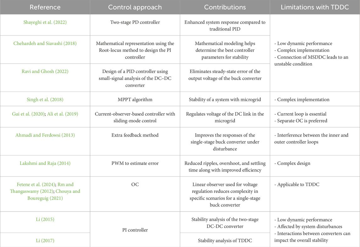
Table 1. Summary of controller approaches and contributions available in the literature and their limitations compared to the TDDC system.
There are some available works on the control of DC–DC converters, but the present study intends to fill a particular gap in this field. The above review focuses primarily on controller designs for traditional converters, which are mainly single-stage converters like buck and boost converters as well as cascaded systems with separate PI controllers for each of the stages (Gui et al., 2020; Rm and Thangaswamy, 2012; Chouya and Boureguig, 2021; Ali et al., 2019). There have been limited investigations into OCs for two-stage DC–DC converters. The main contribution of the present research is the design of an OC specifically for the TDDC. Although OCs have been developed for single-stage converters like those mentioned in Chouya and Boureguig (2021), their application to a TDDC with variable input and specific load demands can be considered new and innovative. Previous studies acknowledge the concerns arising from the varying input voltages from PV sources and highlight the performance problems of the TDDC when integrated with a PV system (Ali et al., 2019). According to literature, OCs perform better than PI controllers when used together in TDDCs with PV panels, but there is limited information regarding their performance comparisons (Li, 2015; Li, 2017).
1.2 Contributions
This paper presents the implementation of a TDDC with an OC, where each stage of the buck converter is equipped with its own dedicated OC control loop. The controller is designed on the basis of an observer algorithm that estimates the system states and adjusts the control inputs accordingly. This approach enhances the system stability and performance, ensuring accurate voltage regulation and improved response under varying load conditions and disturbances. Based on the research gap analysis from the literature review, we summarize the contribution of this work as follows:
- Designing the controller to accommodate integration of PV panels with the system.
- Developing an OC for the TDDC system. In particular, an observation topology is adopted to enhance the system responses under various conditions, such as input voltage variations, reference voltage changes, and load fluctuations.
- Enhancing the specified performance parameters of the TDDC. This includes reducing the rise time, eliminating the voltage ripples, and improving the overshoot compared to the PI controller topology.
- Achieving higher overall stability, precise regulation of the target setpoint voltages, and system stability as well as mitigating system transients. To validate these improvements with the proposed system, two controller topologies were evaluated using a simulation program.
1.3 Organization
The remainder of this paper is organized as follows: Section 2 presents the proposed methodology involving the mathematical representation of the DC–DC buck converter in state space; it also introduces the structure and equations of the OC as well as outlines the approach for selecting the feedback gains for the OC. Section 3 details the design of the TDDC with OC along with simulation of the system in Simulink. Section 4 presents a comprehensive analysis and comparison of the system response parameters as well as stability for the TDDC with OC and conventional PI controller. Finally, Section 5 lists the conclusions of this work.
2 Methodology
The control scheme for the MSDDC generally regulates the output voltage of each converter individually before integrating them. Herein, a TDDC with individual OCs is proposed. To ensure system stability, we analyze the integrated converter behavior and select the most suitable controller. We then represent the proposed system using state-space equations and derive steady-state expressions. The separation principle is applied to determine the optimal observer gain matrix for each stage of the buck converter. By analyzing the eigenvalues of the state-space equations with the observer matrix, we assess the system stability and select appropriate controller parameters. Finally, we implement the TDDC with closed-loop OC in Simulink to evaluate the system performances under various conditions.
2.1 Model of the TDDC with OC
The TDDC with OC proposed herein is shown in Figure 1, where each stage of the buck converter is supervised by an individual OC. Thus, it is necessary to establish the mathematical models of all the stages to evaluate the transfer function of the OC in each loop. The PI controller parameter values are selected as specified in Li (2017).
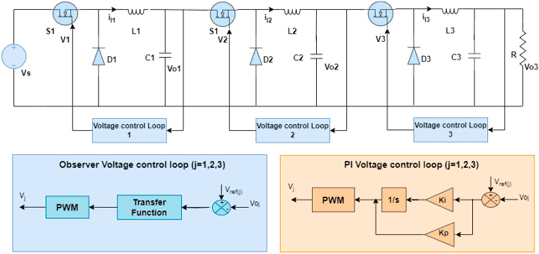
Figure 1. Three-stage DC–DC buck converter (TDDC) system with independent proportional–integral (PI) voltage control loops.
2.2 Mathematical model of the DC–DC buck converter
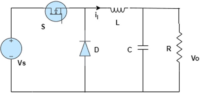
The mathematical model of the DC–DC converter is used to compute the transfer function, which will then be utilized to design the OC gains. Figure 2 shows the circuit of the buck converter, where the state variables are denoted as [il, vo]. The corresponding state equations are expressed as follows (Delchamps, 1998):
The system state-space equations are defined as (Gui et al., 2020)
where
The state-space matrices are as follows:
The transfer function of the buck converter is computed as follows (Delchamps, 1998):
Finally, the transfer function of the buck converter is given by
2.3 Structure of the OC
State observers are widely used in various engineering fields for aerospace, robotics, and process control applications to enhance the performance and robustness of the control system by providing accurate estimates of its internal state. The combination of an observer and a controller in a control system is often referred to as an OC structure or observer-based control (Song et al., 2020). This structure is designed to enhance the performance and robustness of the control system by incorporating an observer to estimate the internal state variables that are then used by the controller for feedback control (Cimini et al., 2014). The mathematical model of the observer is the same as that of the plant shown in Equation 3, except that the additional term includes the estimation errors arising from inaccuracies in matrices A and B as well as the lack of initial errors. This estimation error is also known as the observation error and shows the variance between the measured and estimated outputs (Ghasemi et al., 2022). The mathematical model of the observer is given as follows (Delchamps, 1998):
where
2.4 State observer control design
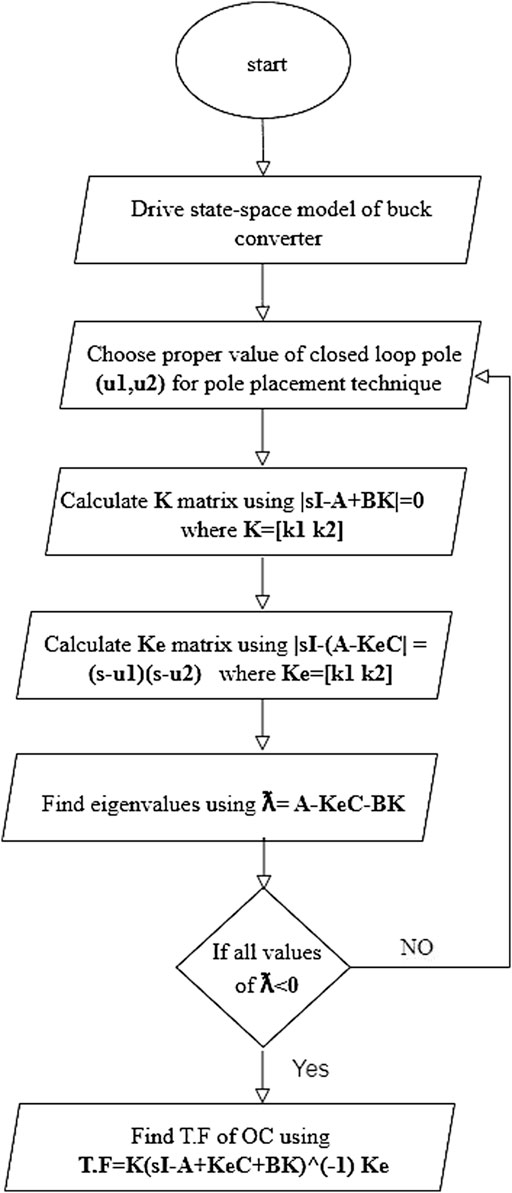
Designing a state observer involves selecting the observer gain matrix that ensures that the estimated state closely tracks the actual state of the system (Vinodh et al., 2013). Figure 4 presents a flowchart outlining the algorithm for designing the OC. The selected gain matrix directly impacts the system performance, influencing factors like the settling time, robustness, and dynamic response. Appropriate tuning of the controller and observer gains is crucial for enhancing the overall system stability and improving the accuracy of state estimation. This leads to better control of the converter, ensuring optimal performance under various operating conditions. The following steps are generally outlined in the design of a system with an OC:
- Derive a state-space model of the system (buck converter).
- Choose appropriate closed-loop poles for pole placement and select the appropriate observer poles.
- Evaluate the state feedback gain matrix K and observer gain matrix Ke.
- Check the system stability using the eigenvalues of (A- Ke C–BK).
- Using the matrices K and Ke, find the transfer function of the OC as
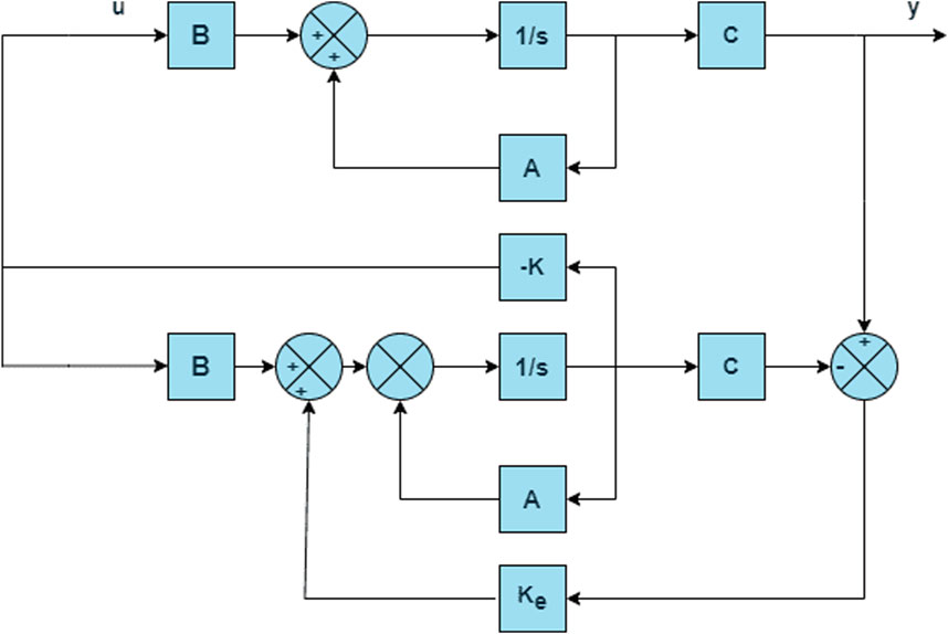
The above steps are applied to all stages of the proposed system to compute three transfer functions for the OC. Figure 5 is a block diagram of a control system with an OC that will be applied to the three loops of the TDDC separately to assess the controller performance and verify its accuracy.
2.5 Simulation setup
To demonstrate the effectiveness of the controller design for the TDDC, it is compared against the PI controller proposed by Li (2017). Simulink was used to simulate and test the performance of the TDDC under different scenarios, and the three-stage buck converter circuit is implemented as shown in Figure 1. Each stage of the buck converter has its own control loop and utilizes the transfer functions evaluated previously. The parameters of the TDDC used in the simulations as well as the controller gains and values of all blocks are provided in Table 2.
3 Results
The OC implementation significantly reduced the values of all parameters of the TDDC across all three loops compared to the PI controller (Li, 2017). Figure 6 illustrates the advantages of employing the proposed OC over those of the PI controller suggested by Li (2017) in terms of the output voltage performances. Specifically, the rise/fall times reduced from 43 ms to 3 ms, 44 ms to 0.5 ms, and 40 ms to 0.1 ms in loops 1–3, respectively. Additionally, the settling time decreased notably from 55 ms to 3 ms, 78 ms to 0.5 ms, and 61 ms to 0.1 ms in these three loops when deploying the OC instead of the PI controller, leading to faster stabilization of the system. The OC also eliminated the output voltage overshoot occurring in the system with the PI controller, which was 100% in loop 2 and 150% in loop 3. Reduced voltage oscillation around the setpoint is a critical indicator of the accuracy and stability of the TDDC. With the implementation of the OC, the voltage fluctuations decreased significantly from 13% to 2%, 28% to 2.3%, and 16% to 0.3% across the three loops compared to the PI controller. For a comprehensive understanding of the effects of the two controllers, Table 3 presents the values of the system parameters. Furthermore, the TDDC was tested under six different cases to demonstrate its system responses under various circumstances.
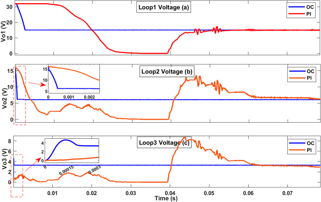
Figure 6. Responses of the TDDC with proposed OC against the PI controller reported by Li (2017) for the three converter loops: (A) loop 1 with a setpoint voltage of 15 V; (B) loop 2 with a setpoint voltage of 6 V; (C) loop 3 with a setpoint voltage of 3.3 V.

Table 3. Parameters of the TDDC with proposed OC against the PI controller in Li (2017).
3.1 Case 1: load fluctuations
In the first scenario, the system responses to load changes are examined to clarify the behaviors under transient conditions. Figure 7 presents the output voltage responses of the TDDC employing the OC against those of the PI controller topology (Li, 2017). The figure illustrates the impacts of a load change from 0.5 Ω to 0.25 Ω at 0.1 s on these two controllers. Reducing the load by half shows the system responses under sudden changes in operational demand and highlights its performance when all the parameters vary. The output overshoots of the two controllers occurring at load change are nearly equal. With the OC, the voltage oscillation around the setpoint reduced from 33% to 2.7% in loop 1, from 16% to 5% in loop 2, and by 12% in loop 3 compared to the PI controller, indicating improved accuracy of the TDDC with the OC.
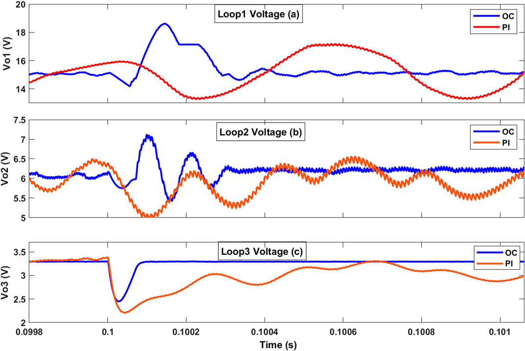
Figure 7. Responses of the TDDC with proposed OC against the PI controller in Li (2017) when the load is changed from 0.5 Ω to 0.25 Ω at 0.1 s for the (A) first, (B) second, and (C) third loops.
In another scenario, the load resistance was changed from 0.5 Ω to 0.4 Ω at 0.1 s, followed by a further load change to 0.3 Ω at 0.1002 s. This situation demonstrates how both controllers handle sudden and extreme load variations. Figure 8 illustrates the improvements provided by the OC to the TDDC, showing that the system remains stable despite the rapid load changes. The OC not only maintains system stability but also provides superior voltage regulation compared to the PI controller, especially under worst-case load variation conditions.
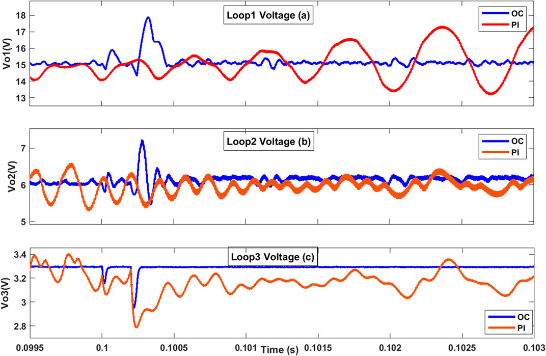
Figure 8. Responses of the TDDC with proposed OC against the PI controller in Li (2017) when the load is changed from 0.5 Ω to 0.4 Ω at 0.1 s and to 0.3 Ω at 0.1002 s for the (A) first, (B) second, and (C) third loops.
3.2 Case 2: reference voltage changes
Altering the reference voltage can influence the output voltage regulation, efficiency, and transient response of the converter directly. Figure 9 presents the responses of the three loops for the two controllers when the reference voltage is changed. At a simulation time of 0.1 s, the reference voltages for the three control loops were adjusted, with the new values being set as 15–20 V, 6–11 V, and 3.3–8.3 V. Achieving the new setpoint upon a reference change is one of the most crucial indicators of system stability that also influences the robustness and sustainability of the controller. An output overshoot occurs in the first loop of the converter with the OC under reference voltage change, which is four times as large as that of the PI controller (Li, 2017); however, the system reaches the new setpoint ten times faster. The OC’s response upon reference voltage change is much faster than that of the PI controller; in particular, the time required to reach the new setpoints reduced from 10 ms to 1 ms, 10 ms to 0.1 ms, and 16 ms to 0.01 ms for loops 1–3, respectively.
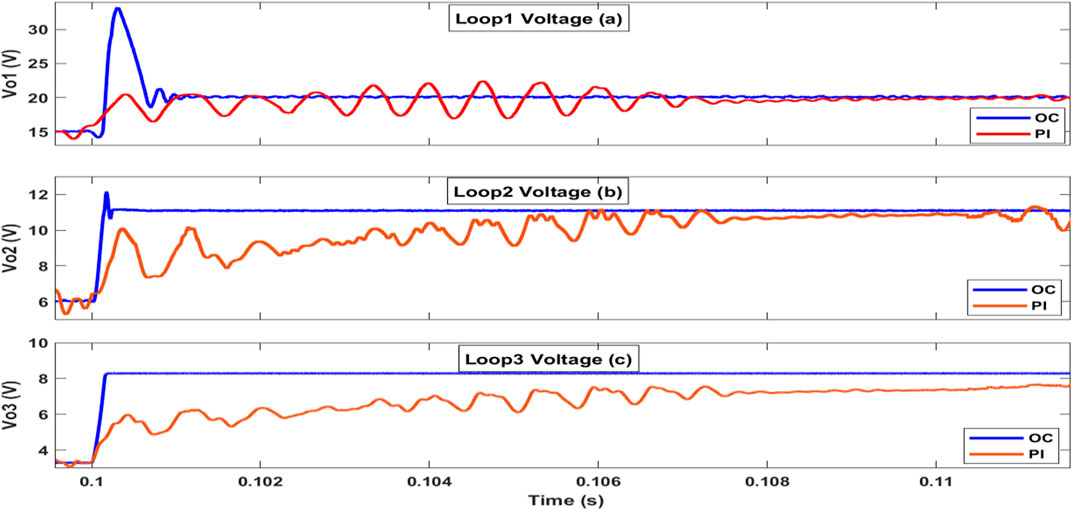
Figure 9. Responses of the TDDC with proposed OC against the PI controller topology in Li (2017) when the reference voltages are subjected to step changes at 0.1 s: (A) loop 1 (15–20 V), (B) loop 2 (6–11 V), and (C) loop 3 (3.3–8.3 V).
In a more challenging scenario, changes in both load and reference voltage were considered simultaneously. The load was changed from 0.5 Ω to 0.25 Ω at 0.1 s, while the reference voltages for the three control loops were adjusted to new values of 15–20 V, 6–11 V, and 3.3–8.3 V. This condition represents the worst-case combination of rapid load changes with dynamic reference voltage adjustments. Figure 10 demonstrates that the TDDC system with the OC maintains greater stability and provides better voltage regulation than the PI controller even under such extreme conditions. During the rapid changes, the system with the OC showed some oscillations in the first loop but reached the desired value more quickly than with the PI controller. Additionally, the third loop responded more smoothly without oscillations and achieved the desired value faster than with the PI controller.
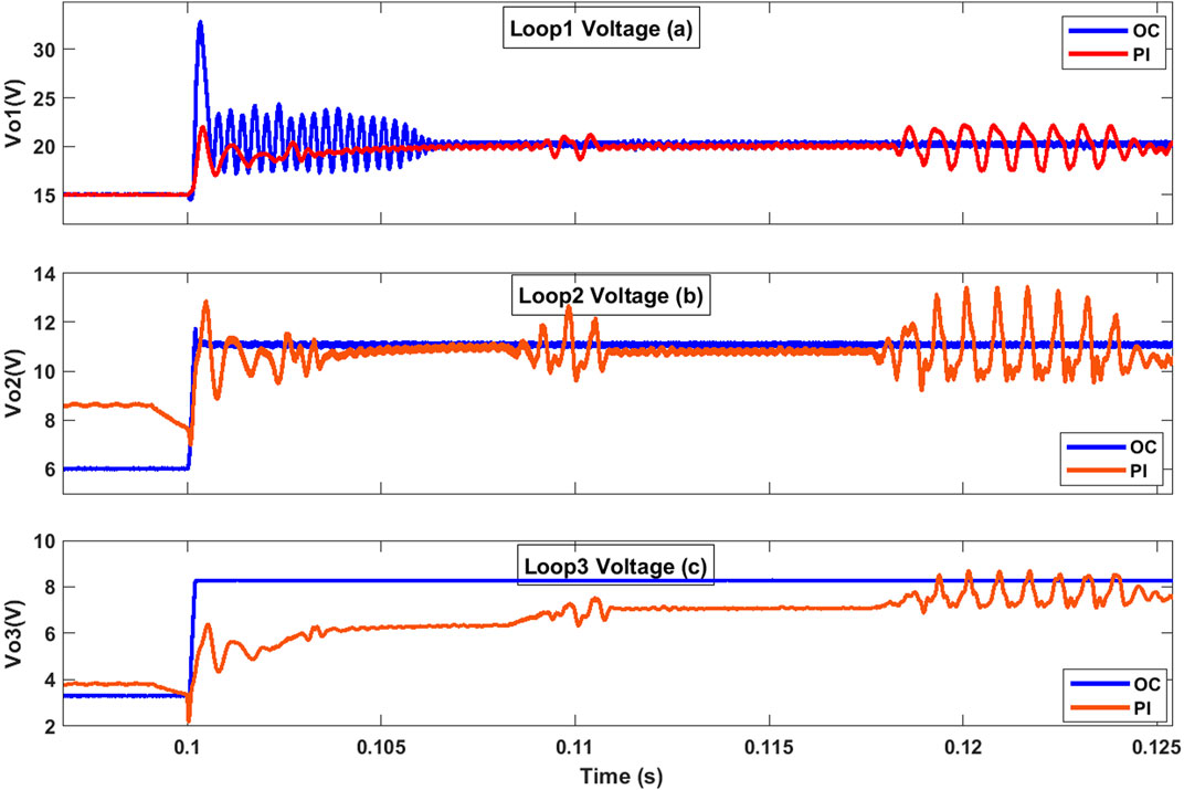
Figure 10. Responses of the TDDC with proposed OC against the PI controller in Li (2017) when load is reduced from 0.5 Ω to 0.25 Ω at 0.1 s and reference voltages are subjected to step changes at 0.1 s: (A) loop 1 (15–20 V), (B) loop 2 (6–11 V), and (C) loop 3 (3.3–8.3 V).
3.3 Case 3: integrating PV sources with the TDDC
Incorporating PV panels with the TDDC facilitates estimation of the system response and evaluation of the performance of each control loop. Figure 11 shows the responses of the proposed system when connected to PV panels, offering insights into its operational dynamics and the efficiencies of the controllers in minimizing voltage ripple while achieving the setpoint voltages. The system stability improved significantly with the OC, resulting in more accurate output voltages across all three loops. Additionally, parameters such as the rising time, settling time, overshoot, and steady-state error were enhanced with the OC implementation. The settling time decreased from 12 ms to 5 ms in loop 1, from 31 ms to 3.7 ms in loop 2, and from 45 ms to 1.7 ms in loop 3. The oscillations reduced from 16% to 3.3% in the second loop and were completely eliminated in the third loop that previously had about 9% oscillations.
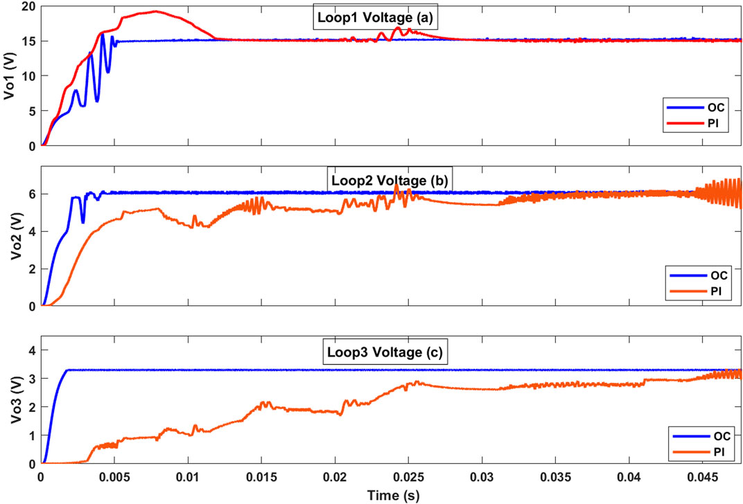
Figure 11. Responses of the TDDC with proposed OC against the PI controller in Li (2017) when PV panels are connected to the input terminals of the (A) first, (B) second, and (C) third loops.
3.4 Case 4: performance of the proposed system on battery charging
Stability of the output voltage of the proposed system ensures consistent and optimal charging current, which is crucial for extending the battery lifespan. Fluctuations can lead to overcharging or undercharging, both of which can damage the battery. Figure 12 shows the performance of the proposed system for charging a battery under the two controller topologies, namely the proposed OC and PI controller. The response describes the state of charge (SOC) of the battery, demonstrating the speed of the controller in charging the battery along with the battery charging current and voltage. The response illustrates the advantages of the OC compared to the PI controller proposed by Li (2017) in terms of stable charging current, reduced voltage ripple, and increased charging speed.
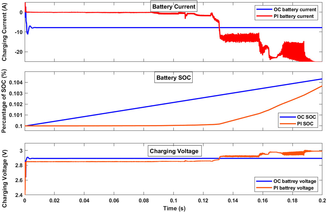
Figure 12. Battery responses of the TDDC with proposed OC against the PI controller in Li (2017) in the battery charging mode for the (A) first, (B) second, and (C) third loops.
3.5 Case 5: voltage regulation under varying weather conditions
Differences in the irradiance levels can directly affect the output voltages of the PV panels. Simulating a buck converter under varying irradiance conditions can showcase how the converter responds to the expected fluctuations in the PV panel’s output voltage. Figure 13 illustrates the performance of the proposed system for varying irradiance levels, where the values are changed linearly from 1000 W/m2 to 100 W/m2. The OC implementation significantly reduced the voltage ripples from 1.7 V to 0.07 V in loop 1, from 0.9 V to 0.1 V in loop 2, and eliminated the 0.3 V ripple in loop 3 compared to those of the PI controller in Li (2017).
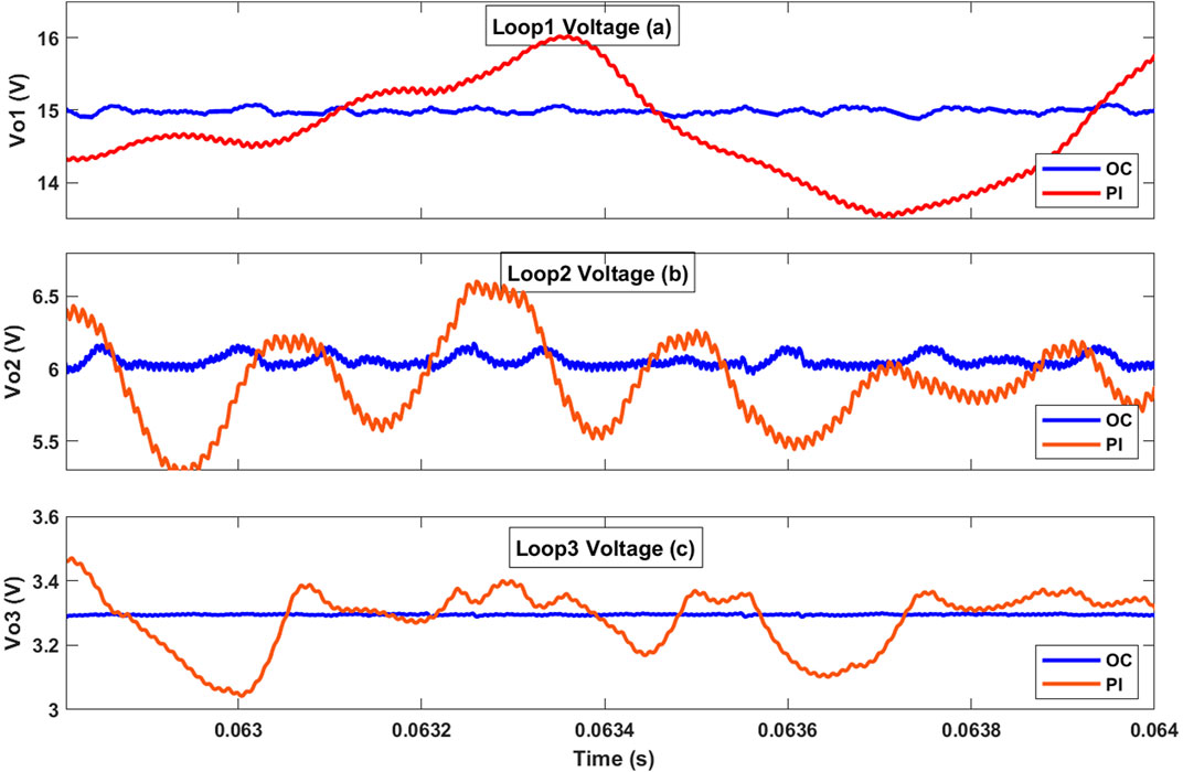
Figure 13. Output voltages of the TDDC with proposed OC against the PI controller in Li (2017) under various solar irradiation conditions for the (A) first, (B) second, and (C) third loops.
3.6 Case 6: voltage regulation under tolerance errors in the system parameters
The controller of the TDDC was designed using system parameter values like capacitance and inductance, so any changes in these values will impact the output voltage stability directly. Capacitance plays a crucial role in smoothing the output voltage ripple and ensuring stability of the converter’s operation. Figure 14 illustrates the responses of the TDDC with the OC and PI controller, where the capacitances of all three buck components were changed by 30% of their values at 0.1 s. The output overshoots observed with the two controllers were nearly equal. However, the OC showed improved output voltage stability after the capacitance changes compared to the PI controller. Specifically, with the OC, the voltage oscillations around the setpoint reduced from 6.7% to 0.7% in loop 1, from 13% to 1.7% in loop 2, and by 12% in loop 3 compared to the PI controller. The OC is suitable in this case as it significantly improves the output voltage stability, thereby reducing oscillations greatly and demonstrating better performance compared to the PI controller.
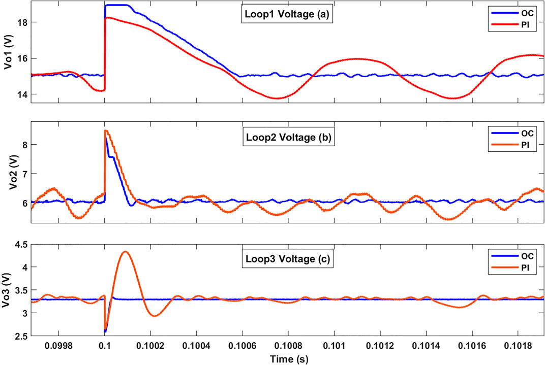
Figure 14. Responses of the TDDC with the OC and PI controller in Li (2017) when the capacitances of the three buck converters are subjected to a step change of 30% at 0.1 s: (A) first, (B) second, and (C) third loops.
4 Discussion
The TDDC with the OC shows outstanding improvement in voltage regulation under load variation. The OC demonstrates notable improvements across all system parameters, showcasing greater stability compared to the PI controller in Li (2017) under load fluctuations. Moreover, the OC demonstrates enhanced output voltage regulation after load changes compared to the PI controller. This means that the OC can be used in applications where load changes occur and for which the voltage must remain constant, such as in microgrids. The OC exhibits greater stability and accuracy in achieving the new setpoint compared to the PI controller. This observation underscores the superior dynamic behavior and performance of the proposed system employing the OC, which is particularly evident for reference voltage fluctuations. The demonstrated high quality of the OC in contrast with that of the PI controller underscores its effectiveness in maintaining stability and precision under varying operating conditions. The faster response time in reaching a new setpoint makes the OC preferable in applications where voltage adjustments are needed.
The integration of PV panels with the TDDC achieves a stable output voltage and reaches steady state faster with the OC than the PI controller. The oscillations around the setpoint voltage in the proposed system with the OC are more stable compared to those with the PI controller. The efficiency of converting the irregular irradiation of a PV panel to a stable output voltage is improved with the OC. It is observed that stability and transient behaviors under diverse operating conditions are enhanced with the OC. Furthermore, when the OC is employed, the voltage ripple and regulation performance of the TDDC with the OC surpass those of the PI controller in Li (2017). The TDDC with OC improves both quality and accuracy when applied to a renewable energy system. Lower ripple in the output voltage and current of the TDDC during battery charging promotes smoother charging and prevents potential battery damage. The SOC enhancement of a battery with significant benefits the OC shortens the charging time compared to the PI controller. Additionally, the OC reduces the voltage and current ripples during battery charging, thus contributing to extended battery life.
The most significant improvement in the TDDC is the regulation of the output voltage in the third loop, which remains stable regardless of disturbances, especially with the OC. This isolation of the third loop is essential in applications where precise voltage regulation is necessary at various levels, such as in telecommunications, renewable energy systems, or electric vehicle power management. Tables 4, 5 summarize the performance comparisons between the proposed OC and PI controller in Li (2017) for the TDDC. The OC shows significant improvements in all the test cases. The improvements achieved with the OC in the proposed system make it promising for application to other types of converters, such as boost converters. Additionally, extending the OC to large-scale systems like microgrids that have diverse loads and sources can offer significant benefits.
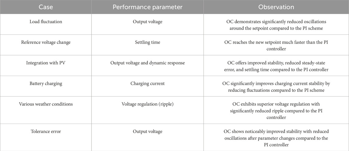
Table 4. Performance comparisons of the OC against the PI controller in Li (2017) for the TDDC.
5 Conclusion
The present paper focuses on the design and analysis of a robust and reliable controller for the TDDC that is used in diverse applications. The performances and efficacies of various control strategies, specifically OC versus PI controllers, in the regulation of the TDDC are thoroughly examined in this paper. The comparisons highlight the significant benefits of the OC, which exhibits better stability and precision in response to variations in the load and reference voltages. Furthermore, the OC exhibits improved dynamic behavior and accuracy, which are especially notable under reference voltage fluctuations. When PV panels (as dynamic non-linear DC input sources) are integrated with the TDDC, the stability and efficiency are further increased because of the improved control loop performance and output voltages. The effectiveness of the OC is also demonstrated for charging a battery (another type of dynamic non-linear DC input source) and various operating environments, underscoring its critical role in optimizing converter performance while ensuring robust and sustainable operation. All-inclusive case studies as presented in this paper demonstrate that the OC is best suited for this particular TDDC application. The results highlight the notable improvements in system responses based on implementation of the developed controller. This improvements to the three loops of the TDDC include reduced fall times from 43, 44, and 40 ms to 3, 0.5, and 0.1 ms as well as decreases in the voltage ripple around the setpoint from 33%, 16%, and 12% to 2.7%, 5%, and 0, respectively. Additionally, the time required to reach the new setpoints were reduced from 10, 10, and 16 ms to 1, 0.1, and 0.01 ms, respectively. The voltage oscillations upon PV integration were reduced from 16% to 3.3% in the second loop and eliminated by 9% in the third loop. Furthermore, the oscillations of the charging current were eliminated, and the speed of battery charging was increased. The OC can also be applied to different types of DC–DC converters, expanding its utility beyond buck converters. Additionally, implementing the TDDC with OC in systems such as microgrids, renewable energy sources, and telecommunications systems can enhance stability, efficiency, and responsiveness. Overall, the OC’s contribution to the TDDC’s ability to isolate loops and respond to dynamic conditions makes it ideal for use in advanced power systems requiring precise control and high stability.
Future works based on these findings involve implementation of the TDDC and comprehensive stability analyses of the proposed system using advanced stability methods, such as Floquet theory. This is expected to provide a deeper understanding of the dynamic behaviors and robustness of the TDDC under various operating conditions.
Data availability statement
The original contributions presented in the study are included in the article/Supplementary Material; further inquiries can be directed to the corresponding author.
Author contributions
KA: conceptualization, data curation, formal analysis, investigation, methodology, software, validation, visualization, and writing–original draft. AA: data curation, investigation, methodology, software, validation, visualization, and writing–original draft. HB: formal analysis, project administration, supervision, visualization, and writing–review and editing. YA: funding acquisition, investigation, project administration, resources, validation, and writing–review and editing. SA: formal analysis, methodology, supervision, and writing–original draft.
Funding
The authors declare that no financial support was received for the research, authorship, and/or publication of this article.
Acknowledgments
The authors would like to express their profound gratitude to King Abdullah City for Atomic and Renewable Energy (K.A.CARE) for their financial support in accomplishing this work.
Conflict of interest
The authors declare that the research was conducted in the absence of any commercial or financial relationships that could be construed as a potential conflict of interest.
Publisher’s note
All claims expressed in this article are solely those of the authors and do not necessarily represent those of their affiliated organizations, or those of the publisher, the editors, and the reviewers. Any product that may be evaluated in this article, or claim that may be made by its manufacturer, is not guaranteed or endorsed by the publisher.
Abbreviations
MOA, mayfly optimization algorithm; MPPT, maximum power point tracking; MSDDC, multistage DC–DC converter; OC, observer controller; PD, proportional–derivative; PI, proportional–integral; PID, proportional–integral–derivative; PV, photovoltaic; PWM, pulse-width modulation; SOC, state of charge; TDDC, three-stage DC–DC buck converter.
References
Ahmadi, R., and Ferdowsi, M. (2013). Improving performance of a DC-DC cascaded converter system using an extra feedback loop. IEEE Energy Convers. Congr. Expo., 5511–5517. doi:10.1109/ecce.2013.6647449
Ahmadi, R., Paschedag, D., and Ferdowsi, M. (2011) “Analyzing stability issues in a cascaded converter system comprised of two voltage-mode controlled dc-dc converters,” in Twenty-sixth annual IEEE applied power electronics conference and exposition.
Ali, D., Said, D., and Mohamed, T. (2019). Observer-based control of a photovoltaic DC–DC buck converter: HDS approach, Asian Journal of Control, 1927–1940.
AL-Nussairi, M., Bayindir, R., Padmanaban, S., Mihet-Popa, L., and Siano, P. (2017). Constant power loads (CPL) with microgrids: problem definition, stability analysis and compensation techniques. Energies 10 (10), 1656. doi:10.3390/en10101656
Chehardeh, M. I., and Siavashi, E. M. (2018). A closed-loop controller to improve the stability of cascaded DC/DC converters. arXiv Signal Process.
Chouya, A., and Boureguig, K. (2021). Linear Observer based linearizing control of DC-DC buck converter. WSEAS Trans. POWER Syst. 16, 52–60. doi:10.37394/232016.2021.16.5
Cimini, G., Ippoliti, G., Orlando, G., Longhi, S., and Miceli, R. (2014) “Robust current observer design for DC-DC converters,” in International conference on renewable energy research and application.
Delchamps, D., Stability of state space linear systems (1998) in State space and input-output linear systems, p. pp. 322–349.
Errouissi, R., Shareef, H., Viswambharan, A., and Wahyudie, A. (2022). Disturbance-observer-based feedback linearization control for stabilization and accurate voltage tracking of a DC–DC boost converter. IEEE Trans. INDUSTRY Appl. 55 (5). doi:10.1109/TIA.2022.3183040
Fetene, Y., Ayenew, E., and Feleke, S. (2024). Full state observer-based pole placement controller for pulse width modulation switched mode voltage-controlled buck Converter. Heliyon 10, e30662. doi:10.1016/j.heliyon.2024.e30662
Ghasemi, M., Zarei, S., Sohrabi, Z., Blaabjerg, F., and Peyghami, S. (2022). An observer-based current sensor-less control scheme for grid-following converters. Apply Since.
Gui, Y., Blaabjerg, F., Wang, X., Bendtsen, J., Yang, D., and Stoustrup, J. (2020). Improved DC-link voltage regulation strategy for grid-connected converters. IEEE Trans. Industrial Electron. 68, 4977–4987. doi:10.1109/tie.2020.2989720
Hinov, N., and Grigorova, T. (2023) Design considerations of multi-phase buck DC-DC converter. MDPI Appl. since 11064, 13. doi:10.3390/app131911064
Lakshmi, S., and Raja, T. (2014) Design and implementation of an observer controller for a buck converter, TURKISH J. Electr. Eng. Comput. Sci., 22, 562–572. doi:10.3906/elk-1208-41
Li, H. e. a. (2015) “A novel stability analysis method based on Floquet theory for cascaded DC-DC converters system,” in IEEE energy conversion congress and exposition (ECCE).
Li, H. e. a. (2017) “A stability analysis method based on Floquet theory for multi-stage DC-DC converters system,” in IEEE energy conversion congress and exposition (ECCE).
Magaldi, G., Serra, F., de Angelo, C., Montoya, O., and Giral-Ramírez, D. (2021). Voltage regulation of an isolated DC microgrid with a constant power load: a passivity-based control design. Electronics 10, 2085. doi:10.3390/electronics10172085
Ravi, D., and Ghosh, A. (2022). “Voltage mode control of buck converter using practical PID controller,” in International conference on intelligent controller and computing for smart power (ICICCSP)/IEEE (SOUTHERN METHODIST).
Rm, S., and Thangaswamy, S. R. R. (2012). Observer based pole placement and linear quadratic optimization for DC-DC converters. J. Electr. Eng., 121–128.
Shayeghi, H., Rahnama, A., Takorabet, N., Thounthong, P., and Bizon, N. (2022). Designing a multi-stage PD(1+PI) controller for DC–DC buck converter. Energy Rep. 8, 765–773. doi:10.1016/j.egyr.2022.10.448
Singh, G., Urooj, S., and Haque, A. (2018). “Regulation of DC bus voltage for DC microgrid using PSIM,” in 5th IEEE Uttar Pradesh section international conference on electrical, electronics and computer engineering, UPCON.
Song, L., Liu, P., Duan, S., and Liu, X. (2020) “A stability analysis method for input-series output-parallel DC-DC converter system,” in IEEE 9th international power electronics and motion control conference.
Veerachary, M., and Sudhakar, S. B. (2007) “Stability analysis of cascaded DC-DC power electronic system,” in 7th international conference on power electronics and drive systems.
Keywords: observability design, buck converter, cascaded buck, voltage stability, voltage control
Citation: Albariqi KA, Alhussainy AA, Bawayan H, Alturki YA and Alghamdi S (2024) Efficient voltage control strategy: observability design for multistage DC–DC buck converter. Front. Energy Res. 12:1485269. doi: 10.3389/fenrg.2024.1485269
Received: 23 August 2024; Accepted: 14 October 2024;
Published: 12 November 2024.
Edited by:
Soumya Ranjan Das, Parala Maharaja Engineering College (P.M.E.C), IndiaReviewed by:
Wulfran Fendzi Mbasso, University of Douala, CameroonDevi Prasad Acharya, Parala Maharaja Engineering College (P.M.E.C), India
Imane Hammou Ou Ali, Mohammed V University, Morocco
Copyright © 2024 Albariqi, Alhussainy, Bawayan, Alturki and Alghamdi. This is an open-access article distributed under the terms of the Creative Commons Attribution License (CC BY). The use, distribution or reproduction in other forums is permitted, provided the original author(s) and the copyright owner(s) are credited and that the original publication in this journal is cited, in accordance with accepted academic practice. No use, distribution or reproduction is permitted which does not comply with these terms.
*Correspondence: Sultan Alghamdi, c21hbGdhbWRpMUBrYXUuZWR1LnNh
 Khalid A. Albariqi
 Abdullah Ali Alhussainy2
 Sultan Alghamdi