- 1Aviation Engineering Institute, Jiangsu Aviation Technical College, Zhenjiang, China
- 2China National Research Center of Pumps, Jiangsu University, Zhenjiang, China
- 3School of Mechanical Engineering, Jiangsu University, Zhenjiang, China
The volumetric efficiency of the hydrogen circulation pump (HCP) is mainly affected by the amount of leakage in working clearances. Studying the leakage characteristics of working clearances is of great significance for optimizing the performance of the HCP. Therefore, this paper developed a three-blade elliptical conjugate rotor HCP, and compared the results of experiments and simulations for different working conditions. On this basis, the flow rate, pressure, and internal flow field changes of radial clearance models and axial clearance models with four different scales of 0.1mm, 0.14mm, 0.18mm, and 0.22 mm were studied. The results indicate that: under four different pressure ratios and rotational speeds, the simulation results using the overlapping grid method showed a maximum difference of 4.17% compared to the experimental results, verifying the reliability of the simulation calculation method; the average flow rate of the HCP is linearly inversely proportional to both the radial clearance and the axial clearance, with a decrease rate of 11.6 Nm3/h and 5.8 Nm3/h as the clearance size increases by 0.04 mm; the radial clearance leakage of the same size is higher than the axial clearance, the leakage value in the radial clearance between the rotors is higher than that between the rotor and the pump casing, and the internal leakage of axial clearance is not evenly distributed, with higher leakage value in the middle area than that in the left and right areas.
1 Introduction
The hydrogen circulation pump (HCP) is an important equipment in fuel cell systems, used to recover hydrogen gas that has not been consumed by the fuel cell stack, and to pressurize and deliver it to the stack inlet to improve fuel cell efficiency (Wiebe et al., 2020; Liu et al., 2020; Fan et al., 2021; Alami, 2021). Roots HCP has the advantages of simple structure, high reliability, and low cost, which is suitable for high-flow application environments and has become the mainstream research direction currently (Wang et al., 2019; Wu et al., 2023). To improve the flow characteristics of Roots type hydrogen circulation pumps, current research focuses on optimizing the design of rotor profiles (Zhai et al., 2022; Li et al., 2024; Lin et al., 2021) and optimizing design parameters such as rotor blade number (Li et al., 2021; Chen and Zou, 2019), helix angle (Zhai et al., 2024; Zhang, 2018), diameter to pitch ratio (Li et al., 2023; Yang et al., 2022). The working clearance is also an important design parameter for HCPs. The smaller the clearance size, the higher the volumetric efficiency of the pump, but the greater the difficulty of machining and assembling the various components of the HCP. Therefore, it is necessary to study the leakage characteristics of the work clearance and find a suitable balance point.
Working clearances include two types: radial clearance and axial clearance. The radial clearances include the radial clearance between rotors and the radial clearance between the rotor and the pump casing. On the one hand, there is a correlation between the working gap size and the volumetric efficiency of the HCP. Lin and Lin (2022). concluded through simulation that as the radial clearance increased, more gas leaked from the high-pressure exhaust chamber to the low-pressure intake chamber, resulting in a decrease in the actual flow rate of the HCP. Liang et al. (2024). conducted numerical calculations on seven sets of pumps with different working clearances to study the influence of working clearances, and concluded that the actual exhaust flow rate of the pump decreased from 37.46 to 32.73 m3/h when the meshing clearance increased from 0.15 to 0.21 mm. According to Rao L.'s research (Rao and Zhong, 2021), under the condition of constant rotational speed, as the axial clearance increased, the volumetric efficiency of the rotor pump decreased significantly; under the condition of constant axial clearance, the volumetric efficiency of the rotor pump increased with the increase of rotational speed. These three studies indicate that an increase in working clearance size will reduce the volumetric efficiency of the HCP. Singh et al. (2019). used a high-speed camera, a high-speed particle image velocimeter, and other equipment to conduct instantaneous PIV experiment for Roots blower, and compared the experimental results with CFD unsteady simulation results, which confirmed that the increase of working clearance size would reduce the volumetric efficiency of Roots blower. Because the Roots blower has a similar structure to the Roots HCP, this experimental verification result can be used for reference.
On the other hand, changes in the size of the working clearance have an impact on the internal flow field and flow stability of the HCP. Li et al. (2022). studied the effect of radial clearance size variation on the flow characteristics of rotor pumps, and the conclusion was that when the clearance size increased from 0.1 mm to 0.3mm, the area and intensity of vortices in the pump cavity increased, resulting in a decrease in flow stability. Rao and Zhong (2021) found that as the increase of axial clearance size, the flow pulsation characteristics did not show a significant change.
It can be found that there is relatively little research on the leakage characteristics of the working clearance of the HCP, and more research is based on the reference of rotor pumps with similar structures in other industries. The current research mainly focuses on the correlation between the size changes of radial or axial clearances and the output flow rate, without conducting systematic research on the leakage characteristics of working clearances, and the depth of research on leakage mechanisms is insufficient. Therefore, this paper will establish a three-blade elliptical conjugate rotor HCP, and use experimental and overlapping grid simulation methods to systematically study the effects of radial clearance and axial clearance on the flow rate, pressure, and internal flow field of the HCP, providing theoretical guidance for the rational design of the clearance size.
2 Model design and theoretical calculation
2.1 Model design
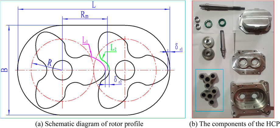
This article adopts the previous design method (Zhai et al., 2022) to design a three-blade elliptical conjugate rotor HCP for studying the leakage characteristics of the working clearance. The design parameters of the HCP include the length of the pump chamber L = 111 mm, the width of the pump cavity B = 66, and the height of the pump cavity D = 40 mm, shown in Figure 1. The HCP includes four working clearances, namely, the radial clearance δr1 between the rotor and the pump casing, the radial clearance δr2 between the two rotors, the axial clearance δa1 between the rotor and the upper cover, the axial clearance δa2 between the rotor and the bottom of pump cavity. Usually, the values of the two types of radial clearances are equal, designed as δr1 = δr2 = 0.10mm; the values of the two types of axial clearances are equal, designed as δa1 = δa2 = 0.10 mm. Then, record the section of the elliptic curve as L1, the conjugate curve as L2, and design the rotor profile according to Equation 1.
Where, x0 is the variable parameter of the elliptic curve, x0 = 5 (in this article); Rm is the top circle radius of the rotor profile,
2.2 Theoretical calculation
After completing the model design of the hydrogen circulation pump, calculate the theoretical flow rate according to Equation 2.
Where, Q0is the theoretical flow rate without considering compression, leakage, and other factors, Nm3/h; n is the pump speed, r/min; D is the height of the pump chamber, m; Sc is the cross-sectional area of the concave cavity between the two blades of the rotor.
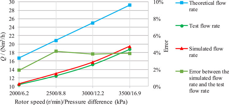
When the rotational speeds are 2000 r/min, 2500 r/min, 3,000 r/min, and 3,500 r/min respectively, the theoretical flow rates of the HCP are calculated to be 16.70 Nm3/h, 20.88 Nm3/h, 25.06 Nm3/h and 29.23 Nm3/h.
3 Prototype test and simulation
3.1 Prototype test
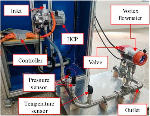
Figure 2 shows the HCP testing system, which uses high-frequency pressure sensors to test the real-time pressure, a vortex flowmeter to test the average flow rate, a temperature sensor to test the temperature of the output gas, the control valve at the end to adjust the outlet pressure of the HCP. For safety reasons, the air medium is used to test the flow-pressure characteristics of the HCP, so the inlet of the HCP testing system is open. Figure 2 shows the comparison of the simulation and testing results of the HCP prototype under air medium.
Adjust the opening of the control valve to 10% and keep it unchanged. When the speed of the HCP is set to 2000r/min, the measured flow rate is 10.38Nm3/h and the pressure is 6.2kPa; when the speed is set to 2500r/min, the measured flow rate is 12.48Nm3/h and the pressure is 8.8kPa; when the speed is set to 3000r/min, the measured flow rate is 15.12Nm3/h and the pressure is 12.2kPa; when the speed is set to 3500r/min, the measured flow rate is 18.72Nm3/h and the pressure is 16.9 kPa. The ratio of the test flow rate to the theoretical flow rate is defined as volumetric efficiency.
3.2 Simulation method
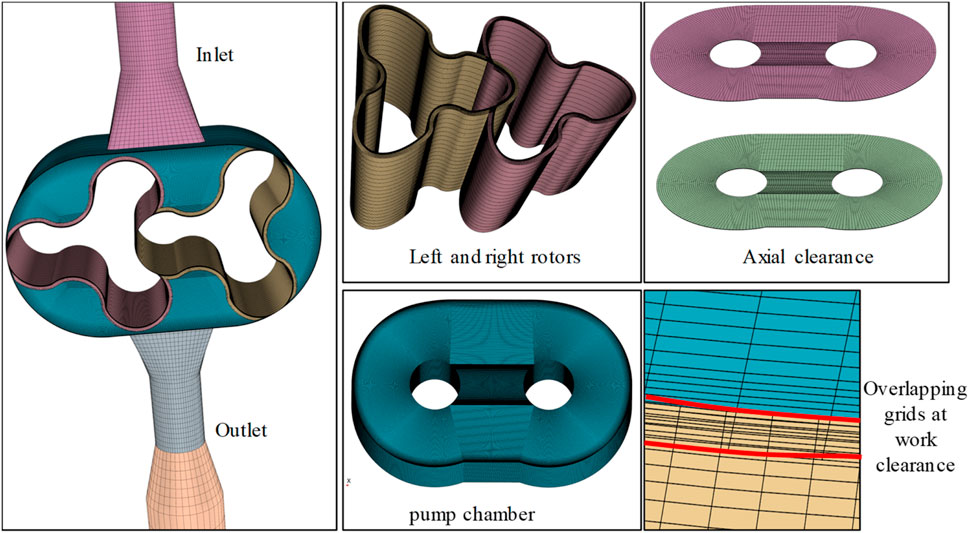
The overlapping grid method of STAR-CCM is used to calculate the turbulence of the HCP models, and the established hexahedral grid model is shown in Figure 3. The grid model of HCP is composed of a pump body, rotors, inlet, outlet, upper axial clearance, and lower axial clearance. The number of grid layers in the overlapping area at the work clearance is bigger than 5, which meets the requirements of the minimum 4 layers of the overlapping grid and has high reliability.
The inlet and outlet of the HCP model are set as pressure boundaries, with the inlet pressure value set to 0 and the outlet pressure set based on experimental data. For example, when the speed of the two rotors is set to 2000r/min, the outlet pressure is set to 6.2 kPa. The realizable k-ε two-layer model which can well simulate the complex motion of the whole flow field, is selected as the turbulence model.
3.3 Comparison between experimental data and simulation data
Figure 4 compares the simulated flow rate with the test flow rate. It can be observed that the flow rates under four different states are 10.58Nm3/h, 13.0Nm3/h, 15.70Nm3/h, and 19.45Nm3/h, and the differences with the test flow rates are 1.93%, 4.17%, 3.84%, and 3.90%, respectively. The low differences indicate both the reliability of the experimental results and the feasibility of the overlapping grid method used to study the leakage characteristics of working clearances.
Defining volumetric efficiency as the ratio of test flow rate to theoretical flow rate. It can be obtained that the volumetric efficiency at four speeds is 62%, 60%, 60%, and 64%, respectively. It should be noted that the volumetric efficiency is generally proportional to the rotor speed and inversely proportional to the pressure ratio, but the volumetric efficiency of the four states analyzed here is basically unchanged because the pressure ratio also increases with the increase of the speed, and the influence of the two on the volumetric efficiency is offset each other. Volume efficiency is an important parameter reflecting the performance of HCPs, and its value is determined by the leakage characteristics of the working clearance. The leakage characteristics of radial clearance and axial clearance are studied using simulation methods.
4 Research on leakage characteristics of working clearances
The simulation method is used to study the leakage characteristics of working clearances. The hydrogen medium is used, the rotor speed is set at 6000r/min, and the output pressure is set at 10 kPa.
The parameters such as the length, width, and height of the pump housing cavity remain unchanged, and different HCP models are designed by adjusting the radial and axial clearances. For ease of expression, the model number is denoted as HCPX-Y, where X = δr1 = δr2, Y = δa1 = δa2. For example, when the radial clearances δr1 = δr2 = 0.10 mm and the axial clearances δa1 = δa2 = 0.14 mm, the model can be expressed as HCP10-14.
4.1 Leakage characteristics of radial clearances
To research the effect of radial clearances on the output flow rate and pressure of the HCP, the axial clearance is designed as 0, and the radial clearances are sequentially designed as 0.10mm, 0.14mm, 0.18mm, and 0.22mm, resulting in four radial clearance models: HCP10-0, HCP14-0, HCP18-0, and HCP22-0.
Figure 5 shows the comparison of output flow rates among four radial clearance models, where Figure 5A shows the relationship between the average flow rate and the radial clearance size, and Figure 5B shows the relationship between the real-time flow rate and the rotation angle of the rotor. It can be found that the average flow rates of the four models HCP10-0, HCP14-0, HCP18-0, and HCP22-0 are 45.0Nm3/h, 31.0Nm3/h, 22.4Nm3/h, and 10.2Nm3/h, respectively, showing a linear decreasing trend at a rate of approximately 11.6Nm3/h when the radial clearance size increases by 0.04mm; the number and position of the main peaks and valleys of the four flow curves are the same, but the amplitude decreases and the secondary wave trough between the main wave troughs becomes weaker as the radial clearance size increases, and the phenomenon that the pulsation period of the flow curve is twice the number of rotor blades is becoming increasingly apparent; the output flow of HCP22-0 with the maximum radial clearance size has negative values in some states, indicating that the clearance leakage is higher than the delivery volume at this time, which causes hydrogen reflux. The above phenomenon leads to the conclusion that the increase of the radial clearance size will reduce the average output flow of the HCP, but improve the stability of the output flow to a certain extent.
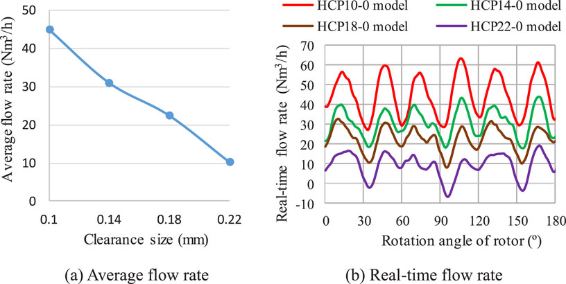
Figure 5. Comparison of output flow rates among radial clearance models. (A) Average flow rate (B) Real-time flow rate.
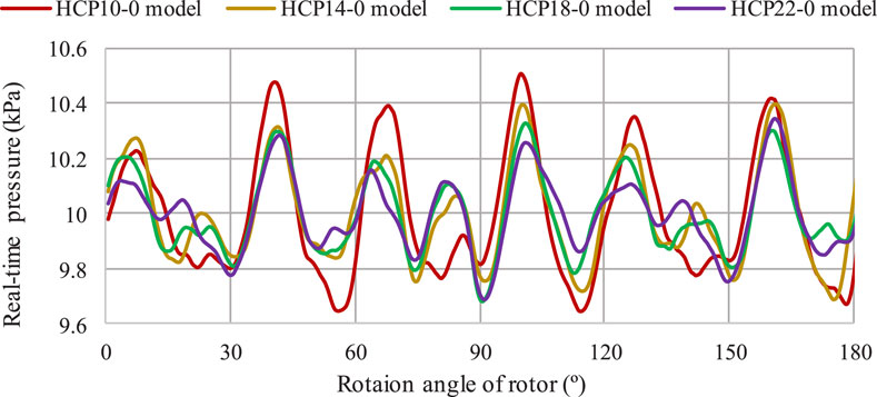
Figure 6 shows the relationship between the real-time pressure and the rotation angle of the four radial clearance models. Although the outlet pressure set during simulation is 10kPa, there are still some differences in the real-time pressure waveforms output by different radial clearance models. It can be found that the pressure curves of the four models have the same pulsation frequency, peak and trough positions, and have similar waveforms; as the increase of the radial clearance size, the fluctuation amplitude of the output pressure curve gradually decreases, and the output becomes more stable.
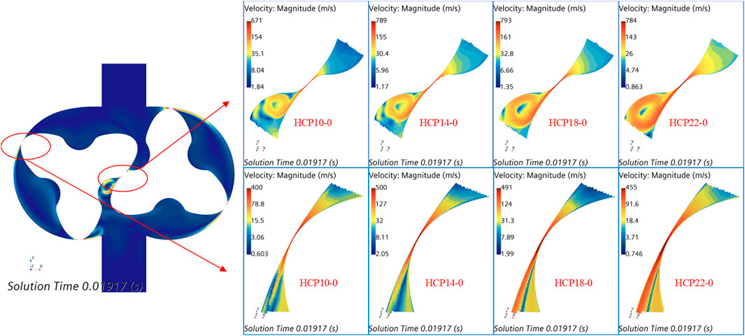
Figure 7 shows the comparison of internal leakage velocity fields of four radial clearance models in a certain state. It can be observed that the maximum flow velocity at the radial clearance between the two rotors is higher than that at the radial clearance between the rotor and the pump casing, indicating that the internal leakage of the radial clearance between the rotors is higher than that between the rotor and the pump casing; as the radial clearance size increases, there is no significant increase or decrease trend in the maximum leakage flow rate, but the leakage amount increases significantly, indicating a linear relationship between the leakage amount and the clearance size, which is consistent with the analysis conclusion in Figure 5A earlier.
4.2 Leakage characteristics of axial clearances
When studying the effect of axial clearance on the output flow rate and pressure of the HCP, the radial clearance is designed to be 0.10 mm because the motion clearance cannot be designed to be 0. By designing axial clearances of 0.10mm, 0.14mm, 0.18mm, and 0.22mm, four axial clearance models are obtained: HCP10-10, HCP10-14, HCP10-18, and HCP10-22.
Figure 8 shows the comparison of output flow rates among four axial clearance models, where Figure 8A shows the relationship between the average flow rate and the radial clearance size, and Figure 8B shows the relationship between the real-time flow rate and the rotation angle of the rotor. It can be found that the average flow rates of the four models HCP10-10, HCP10-14, HCP10-18, and HCP10-22 are 39.2Nm3/h, 32.4Nm3/h, 28.2Nm3/h, and 21.9Nm3/h, respectively, showing a linear decreasing trend at a rate of approximately 5.8Nm3/h when the axial clearance size increases by 0.04mm; the real-time flow curves of the four models have high waveform similarity, with identical numbers and positions of peaks and valleys, and little change in amplitudes, indicating that changes in axial clearance size have minimal impact on the flow waveform. The above phenomenon leads to the conclusion that an increase in axial clearance size will reduce the average output flow rate of HCP without improving the stability of the flow waveform. Comparing the calculation results of the axial clearance model and the radial clearance model, the flow rate of the HCP10-10 model is lower than that of the HCP10-0 model. However, as the clearance size increases, the flow rate of the axial clearance model decreases much slower than that of the radial clearance model. The flow rate of the HCP10-22 model has reached more than twice that of the HCP22-0 model, indicating that the axial clearance leakage of the same size is lower than the radial clearance leakage.
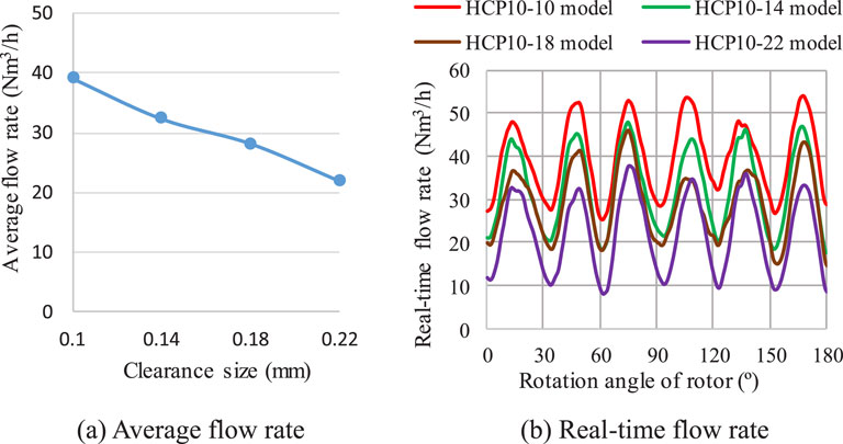
Figure 8. Comparison of output flow rates among axial clearance models. (A) Average flow rate (B) Real-time flow rate.
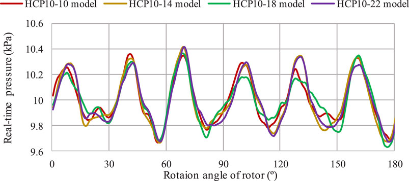
Figure 9 shows the relationship between the real-time pressure and the rotation angle of the four axial clearance models. It can be found that the output pressure curves of the four models are highly similar, and the fluctuation amplitude does not change with the increase of the clearance size, always in a stable state, indicating that the influence of axial clearance on output pressure is relatively small.
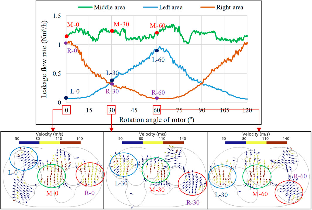
To study the distribution of leakage flow field in the axial clearance, the axial clearance is divided into three regions: left, middle, and right, represented by letters such as L, M, and R. Figure 10 shows the relationship between the internal leakage flow rate and the rotor operating angle in these three regions. It can be found that during the whole fluctuation cycle, the leakage flow rate in the middle area is relatively stable and large, and the corresponding leakage velocity is high; the leakage flow rate of the left and right areas fluctuates alternately, that is, as the left area gradually rises from the lowest point to the highest point, the right area gradually decreases from the highest point to the lowest point. From this, it can be concluded that the overall axial clearance leakage is stable, independent of the rotor operating position, and has little impact on the waveform of the output flow rate and pressure of the HCP, which is consistent with the previous analysis results.
5 Conclusion
In this paper, a three-blade elliptical conjugate rotor HCP is designed, and the reliability of the overlapping grid simulation method used to study the leakage characteristics of working clearance is verified based on experimental data. By numerically calculating four different sizes of radial clearance models and four different sizes of axial clearance models, the influence of changes in radial clearance and axial clearance dimensions on the flow rate, pressure, and clearance flow field of the HCP is explored. The main conclusions are as follows:
(1) The maximum difference between the flow rate of the HCP obtained by using the overlapping grid simulation method and the experimental values is 4.17%. The low difference indicates that it is feasible to use the overlapping grid method to study the leakage characteristics of the working gap.
(2) The average flow rate of the HCP is linearly inversely proportional to the size of the radial clearance and axial clearance, with a decrease rate of 11.6Nm3/h and 5.8Nm3/h as the clearance size increases by 0.04mm, indicating that the radial clearance leakage of the same size is higher than the axial clearance. The increase in the size of the radial clearance will make the flow waveform more stable and reduce the amplitude of the pressure waveform, but the increase in the size of the axial clearance has little influence on the flow waveform and pressure waveform.
(3) The internal leakage of radial clearance is linearly related to the clearance size, and the leakage value in the radial clearance between the rotors is higher than that between the rotor and the pump casing. The internal leakage of axial clearance is independent of the operating position of the rotor, but it is not evenly distributed, with a higher leakage value in the middle area than in the left and right areas.
Data availability statement
The original contributions presented in the study are included in the article/supplementary material, further inquiries can be directed to the corresponding author.
Author contributions
HZ: Conceptualization, Writing–original draft. WL: Conceptualization, Writing–review and editing. XC: Software, Writing–review and editing. HM: Methodology, Writing–review and editing. CS: Methodology, Writing–review and editing.
Funding
The author(s) declare that financial support was received for the research, authorship, and/or publication of this article. The work was sponsored by the “Blue Project” of Jiangsu Colleges and Universities, the Sixth Phase of the “169 Project” of Zhenjiang, and the Visiting and Training programs for Teachers in Jiangsu colleges.
Conflict of interest
The authors declare that the research was conducted in the absence of any commercial or financial relationships that could be construed as a potential conflict of interest.
Publisher’s note
All claims expressed in this article are solely those of the authors and do not necessarily represent those of their affiliated organizations, or those of the publisher, the editors and the reviewers. Any product that may be evaluated in this article, or claim that may be made by its manufacturer, is not guaranteed or endorsed by the publisher.
References
Alami, A. H. (2021). Developments of hydrogen fuel cell technologies. Int. J. Hydrogen Energy 46 (8), 5917. doi:10.1016/j.ijhydene.2020.12.039
Chen, Z. B., and Zou, Y. Z. (2019). The effect of rotor blade number on performance of rotor pump. Mach. Des. & Manuf. 03, 196–199. doi:10.19356/j.cnki.1001-3997.2019.03.048
Fan, L. X., Tu, Z. K., and Chan, S. H. (2021). Recent development of hydrogen and fuel cell technologies: a review. Energy Rep. 7, 8421–8446. doi:10.1016/j.egyr.2021.08.003
Li, Q., Wang, H., and Huang, Z. Q. (2022). Research on influence of meshing clearance and number of rotor blades on pump performance. Chin. J. Process Eng. 22 (12), 1666–1675. doi:10.12034/j.issn.1009-606X.221438
Li, S., Li, W., Ji, L. L., Zhai, H., Li, Y., Wang, C., et al. (2023). Effect of pressure ratio on transient flow in hydrogen circulating pump. Int. J. Hydrogen Energy 48 (69), 26937–26950. doi:10.1016/J.IJHYDENE.2023.03.370
Li, Y. B., Li, L., and Liu, J. F. (2021). Numerical study on the aerodynamic performance of multi-blade rotor cavity in the gas circulating pump of fuel cell. J. XiAn Jiaot. Univ. 55 (03), 46–56. doi:10.7652/xjtuxb202103006
Li, Y. K., Li, W., Ji, L. L., He, S., Huang, Y., Li, S., et al. (2024). Analysis of internal flow characteristics in hydrogen circulation pump with variable trochoid ratio profile. Int. J. Hydrogen Energy 61, 1429–1445. doi:10.1016/j.ijhydene.2024.02.288
Liang, S. S., Pang, S. J., Liu, J. Y., and Chen, Z. (2024). Flow field analysis and performance study of a hydrogen circulation pump for proton exchange membrane fuel cell vehicles with different working clearances. Energy Technol. 12 (7). doi:10.1002/ENTE.202400208
Lin, J. W., Zhang, L. X., Dong, L., Liu, H., and Dai, C. (2021). Rotor profile design and motion simulation analysis of hydrogen circulating pump. Int. J. Fluid Mach. Syst. 14 (4), 322–334. doi:10.5293/IJFMS.2021.14.4.322
Lin, X., and Lin, J. W. (2022). Design of working clearance and study on characteristics of hydrogen circulation pump. Pump. Technol. 04, 16–22+26.
Liu, Z. Y., Chen, J., Liu, H., Yan, C., Hou, Y., He, Q., et al. (2020). Anode purge management for hydrogen utilization and stack durability improvement of PEM fuel cell systems. Appl. Energy 275, 115110. doi:10.1016/j.apenergy.2020.115110
Rao, L., and Zhong, Y. C. (2021). Axial clearance effects on performance of gerotor pump using numerical simulation. Mach. Build. & Automation 50 (05), 110–112. doi:10.19344/j.cnki.issn1671-5276.2021.05.029
Singh, G., Sun, S. H., Ahmed, K., Li, Q. H., and Bruecker, B. (2019). Transient flow analysis in a Roots blower: experimental and numerical investigations. Mech. Syst. Signal Process. 134, 106305. doi:10.1016/j.ymssp.2019.106305
Wang, Y. P., Ma, Q. Y., and Zhao, H. H. (2019). Fuel cell engine technology overview. Automot. Dig. 01, 42–47.
Wiebe, W., Thomas, U., and Sven, S. (2020). Hydrogen pump for hydrogen recirculation in fuel cell vehicles. E3S Web Conf. 155, 01001. doi:10.1051/e3sconf/202015501001
Wu, G. P., Yao, D. S., Ji, N., Yu, Y. Y., He, Y., and Liu, M. J. (2023). Optimization of structural parameters of proton exchange membrane fuel cell ejector. Chin. Hydraulics & Pneumatics 47 (3), 115–122. doi:10.11832/j.issn.1000-4858.2023.03.014
Yang, Y. M., Zhang, Z. Y., and Li, L. (2022). Influence of rotor diameter-distance ratio on performance of fuel cell gas circulating pump. J. Aerosp. Power. 37 (09), 1970–1978. doi:10.13224/j.cnki.jasp.20210348
Zhai, H. L., Li, W., Ji, L. L., Li, J. W., and Li, S. (2022). Profile design and performance research of hydrogen circulation pump in fuel cell system. Mechanika 28 (4), 283–293. doi:10.5755/j02.mech.31528
Zhai, H. L., Li, W., Li, J. W., Shen, C., Ji, L., and Xu, Y. (2024). Multifactor and multi-objective coupling design of hydrogen circulation pump. Front. Energy Res. 12. doi:10.3389/fenrg.2024.1358911
Keywords: hydrogen circulation pump (HCP), radial clearance, axial clearance, leakage characteristics, overlapping grid
Citation: Zhai H, Li W, Chu X, Mu H and Shen C (2024) Research on leakage characteristics of working clearances of hydrogen circulation pump. Front. Energy Res. 12:1480551. doi: 10.3389/fenrg.2024.1480551
Received: 14 August 2024; Accepted: 14 October 2024;
Published: 23 October 2024.
Edited by:
Kan Kan, College of Energy and Electrical Engineering, ChinaReviewed by:
Rajesh S. Kempegowda, Inrigo As, NorwayXinchao Wang, University of Wisconsin-Madison, United States
Copyright © 2024 Zhai, Li, Chu, Mu and Shen. This is an open-access article distributed under the terms of the Creative Commons Attribution License (CC BY). The use, distribution or reproduction in other forums is permitted, provided the original author(s) and the copyright owner(s) are credited and that the original publication in this journal is cited, in accordance with accepted academic practice. No use, distribution or reproduction is permitted which does not comply with these terms.
*Correspondence: Huanle Zhai, anN6aGFpaGxAMTYzLmNvbQ==
 Huanle Zhai
 Wei Li
 Xiaomeng Chu1