- Electric Power Research Institute of State Grid Xizang Electric Power Co., Ltd., Lhasa, China
This article proposes a voltage compensation control strategy for the distribution network based on the unified power quality conditioner (UPQC) with battery energy storage systems (BESS) to achieve comprehensive management of the power quality and improve the system dynamic responses. Specifically, aiming at that amplitude and phase jump of the terminal voltage, a capacity configuration compensation scheme is proposed to achieve voltage vector compensation. The series converter is designed to compensate for the amplitude and phase of the load voltage. The parallel converter is designed to realize power compensation and ensure that the grid voltage and current are sinusoidal and in phase. A voltage control approach based on the nonlinear disturbance observer (NDO) is developed for BESS to stabilize the DC bus voltage and improve the anti-interference performance of the current. An NDO is designed to accomplish current disturbance tracking and provide disturbance feedforward compensation. Simulations validate that the proposed approach is effective and feasible.
1 Introduction
WITH the access to distributed energy and the surge of nonlinear loads, the power quality problem of low-voltage distribution network terminals has become increasingly prominent (Mahela et al., 2020). Since power systems become more complex and the demand for electricity continues to grow, maintaining high power quality in distribution networks becomes increasingly challenging. The increasing penetration of renewable energy sources (RES) like solar and wind into the distribution network introduces variability and intermittency, which can further exacerbate power quality problems (Ray et al., 2022). Moreover, the access of nonlinear loads produces a lot of harmonic and reactive power to the distribution network, resulting in voltage distortion, three-phase unbalance, and harmonic pollution. Even it will threaten the safe and stable operation of the grid and cause huge economic losses (Lou et al., 2021; Li et al., 2023). The improvement of power quality in distribution networks has attracted extensive attention of experts from all over the world (Carreno et al., 2024; Li et al., 2024). Due to its diversity in power quality functions, the unified power quality conditioner (UPQC) has become an essential power quality regulation device (Bacon et al., 2022). Combining the advantages of the shunt active power filter and the series active power filter, the UPQC can compensate for power supply voltage, eliminate harmonic current, and realize reactive power compensation (Wang J. et al., 2021).
With the rapid rise of the UPQC, a great deal of theoretical research and engineering practice has been carried out (da Silva et al., 2020; Yang and Jin, 2021; Khosravi et al., 2023; Sanjenbam et al., 2023). Dash and Ray (2021) designed a novel photovoltaic-based UPQC topology and proposed an adaptive control approach to eliminate current distortion and improve system robustness. However, the randomness of photovoltaics is not conducive to the DC voltage stability and will result in power fluctuation. Abdalaal and Ho (2022) proposed an enhanced control scheme without additional sensors to provide reactive power compensation and achieve grid voltage regulation. Xu et al. (2023) presented a dynamic harmonics compensation control strategy for single-phase UPQC to suppress grid voltage harmonics and maintain voltage stabilization. A distributed parallel control scheme of UPQC for the low-voltage distribution network was developed to support the grid voltage and improve the voltage quality of the load in Abdalaal and Ho (2021). Silva et al. (2024) designed a feed-forward control method to accelerate the voltage and current response compensated by UPQC. However, when there are disturbances in the grid, the system cannot obtain an accurate current reference to ensure that the sinusoidal current is not distorted. The structure of the three-phase UPQC was improved to realize the compensation of grid voltage drop and the power factor improvement in Cardoso et al. (2024). This converter does not need the participation of the line-frequency transformer, but the design may require to be simplified. Felinto et al. (2022) developed an improved UPQC in combination with the high-frequency transformer to compensate for load unbalance. The proposed approach requires no control of the DC-DC converter, but it increases the hardware cost and power density. In (Jin et al., 2020), a comprehensive control method for UPQC based on
To suppress voltage fluctuation and provide power support, the energy storage systems (ESS) in the distribution network have been investigated and implemented (Hosseini and Parvania, 2023; Song et al., 2024a; Tziovani et al., 2022). By integrating UPQC with battery energy storage systems (BESS), it becomes possible to enhance the dynamic response of the system, providing rapid compensation during transient events and contributing to overall grid stability (Charalambous et al., 2021; Zhang et al., 2024). A triple-port active bridge UPQC is designed based on the BESS to improve the fault ride-through performance of the DC grid in Yang R. H. et al. (2022). However, it is less effective in improving power quality in the distribution network. Wang H. et al. (2022) proposed an optimal mitigation scheme by combining fixed energy storage equipment and mobile energy storage equipment to attenuate voltage imbalance and mitigate power fluctuation. Monteiro et al. (2024) utilized the charge and discharge characteristics of the BESS and proposed a new multi-objective UPQC to cope with the power quality issues, which compensates for the grid voltage and load current. Combined with superconducting energy storage, Yang R. et al. (2022) proposed a UPQC based on dual active bridge topology to adjust the terminal voltage and current, which has a simple structure and good voltage stabilization capability. By applying ESS to UPQC, an effective compensation control strategy was developed to achieve voltage recovery and current quality regulation in Çelik and Ahmed (2023). However, the scheme increases the cost investment, and the controller design needs to be further optimized. Somayajula and Crow (2014) proposed an ultracapacitor-based UPQC to mitigate distribution network intermittency and enhance grid power quality. However, the stability and smoothness of the DC voltage is not adequately considered. Devassy and Singh (2021) proposed an automatic transition scheme by integrating photovoltaic and ESS into the UPQC to achieve a continuous and smooth power supply to the load.
In this article, a UPQC-based voltage compensation control strategy for distribution networks is proposed to compensate for the load voltage vector and accomplish system power balance. The main contributions of the article are summarized as follows.
1) A capacity configuration compensation scheme for the distribution network is proposed, which achieves the comprehensive compensation of load voltage and improves the output quality of voltage and current. Compared with other approaches (Bacon et al., 2022; Khosravi et al., 2023; Jin et al., 2020), the proposed scheme compensates for the sudden changes of the load voltage amplitude and phase angle.
2) An NDO-based voltage control approach is developed for BESS to guarantee the stability of DC bus voltage while achieving the bus voltage reference tracking. Unlike other control models (Ray et al., 2022; Sanjenbam et al., 2023; Dash and Ray, 2021), the proposed approach accomplishes disturbance compensation and improves the current waveform quality.
3) The nonlinear disturbance observer (NDO) is developed to achieve disturbance tracking and improve the anti-interference ability of the system, which suppresses the impact of current disturbance on DC voltage stability.
The remainder of the article is organized as follows. Section 2 gives the structure of UPQC. The voltage compensation control strategy of the distribution network based on UPQC is proposed in Section 3. Section 4 shows the simulation results of the proposed strategy. Finally, the conclusion is given in Section 5.
2 System description
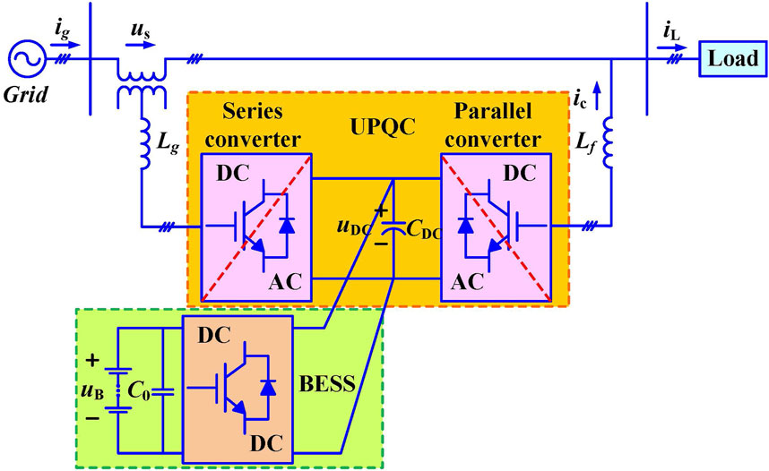
The structure of the UPQC mainly includes the series converter, shunt converter, DC bus capacitor, and BESS, as depicted in Figure 1. When the power supply voltage drops, the series converter is regarded as a voltage source to compensate for the grid voltage vector and ensure the voltage quality at the user side, which is connected in series to the distribution network through inductive filtering. The shunt converter is regarded as a current source, which is connected in parallel to the load side through inductive filtering, to compensate for reactive power, eliminate current harmonics, and ensure the sinusoidal characteristics of the grid current. The BESS is used to maintain DC bus voltage stability and provide load power compensation when necessary.
Based on Kirchhoff’s law, the mathematical model of the UPQC is established as
where
Using the coordinate transformation matrix
where
subscripts
Considering the continuous conduction of the switch tube, the BESS model can be constructed as (Song et al., 2024b)
where
3 Proposed control strategy design
In this section, a voltage compensation control strategy for the distribution network is proposed to achieve comprehensive management of power quality. To address the problem of the voltage jump, a capacity configuration compensation scheme is designed for UPQC to compensate for the amplitude and phase of the load voltage. Then, an NDO-based voltage control approach for BESS is proposed to guarantee the stability of DC bus voltage and suppress voltage fluctuation, where the designed NDO improves the disturbance rejection ability of the system.
3.1 Voltage phasor compensation
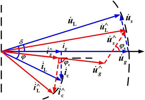
Figure 2 displays the voltage and current phasor diagram of the UPQC. In Figure 2,
When the power grid is operating normally, the load voltage can be denoted as
Then, the voltage amplitude of the series converter can be obtained as
According to the cosine theorem, the voltage phase angle of the series converter can be deduced as
To satisfy the power demand of the load, considering the load
Further, to guarantee that the grid current is in phase with the grid voltage, we have
The capacity of the series converter can be configured as
Similarly, the capacity of the shunt converter can be configured as
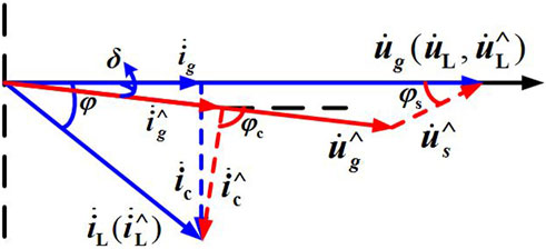
When the grid voltage sags in amplitude and jumps in phase, the UPQC with BESS injects compensation voltage into the grid and provides compensation current to the load, which improves the load voltage quality and provides active power support and reactive compensation. The phasor diagram after voltage and current compensation is depicted in Figure 3. Based on Kirchhoff’s law, the voltage relationship is given as
Since the load voltage and current remain constant before and after the grid voltage drops, the following equation holds.
According to the sine theorem, the following relation can be obtained as
Further, we have
The capacity of the shunt converter when voltage phasor attenuation is encounter, is configured as
Likewise, the capacity of the series converter is configured as
where
When there is a fault in the grid and the connection is interrupted, the power required by the load should be provided by BESS. To ensure uninterrupted power supply to the load, the capacity of the BESS is designed as
where
It can be seen that the proposed compensation scheme realizes the comprehensive compensation of the load voltage vector. When the grid voltage sags, the increase of the shunt compensation current reduces the grid current, which reduces the risk of over-current in the distribution network.
3.2 UPQC control strategy design
In the distribution network, the grid current and load voltage are controllable. In this paper, the voltage compensation control strategy is developed for the UPQC, where the series converter compensates for the grid voltage and the shunt converter compensates for the reactive power of the load, suppresses harmonic current, and ensures the sinusoidal in-phase property between the grid current and grid voltage.
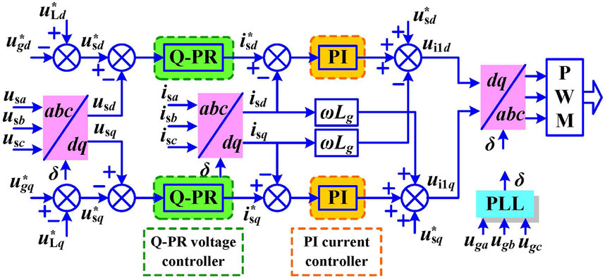
Due to the energy loss and other disturbance factors in the line, the power quality of the load cannot be guaranteed. Especially when encountering faults, the voltage quality of the load will be seriously degraded. To improve the voltage quality of the grid, the control strategy of the series converter is proposed, which is illustrated in Figure 4. It can be noted that compared with other control methods (da Silva et al., 2020; Silva et al., 2024; Jin et al., 2020), the compensation voltage reference
Since the PI controller cannot realize the static error-free tracking for AC component, the quasi-proportional resonant (Q-PR) controllers are employed to achieve voltage tracking without static error and suppress the resonant voltage disturbance. The fundamental frequency current can also realize its reference tracking. The transfer function of the Q-PR controller is expressed as (Song et al., 2024a)
where
To stabilize the sinusoidal grid voltage and compensate for the voltage drop, the voltage control law of the series converter is given as
where
To better achieve voltage control and decouple inductor of the series converter, the compensation voltage reference is fed forward to the current control loop. The current control law of the series converter is given as
where
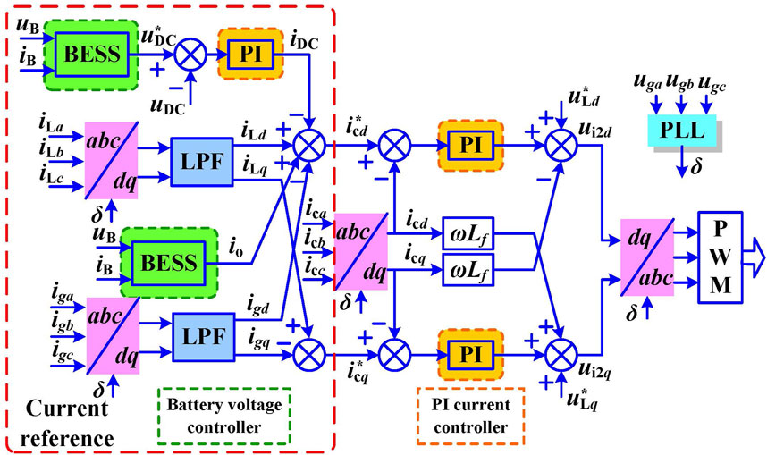
The control strategy of the shunt converter is illustrated in Figure 5. The DC components of the three-phase load current, grid current and compensation current can be obtained by Park transformation. Since the grid current has both fundamental and harmonic components, the low-pass filter (LPF) is adopted to filter out high-frequency harmonics. The DC component in
where
To realize bus voltage regulation and controller power balance, the compensation current reference is designed as
where
To establish a unified control framework, the voltage control of the shunt converter is modified by adding the load voltage reference. The inner current control law is obtained as
where
3.3 BESS voltage controller design
Due to the power change and constant power characteristics at the load terminal, the current disturbance can affect the stability of DC bus voltage, especially in the case of drastic power change. Also, the BESS is connected with the converter, resulting in the existence of the double-frequency component in the current disturbance. The suppression of double-frequency ripple contributes to improving the output power quality and anti-interference performance of the BESS.
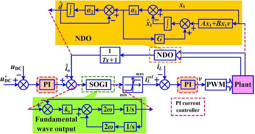
To suppress the fluctuation of DC bus voltage, an NDO-based voltage control approach is proposed in this paper. The DC bus voltage control approach of the BESS is displayed in Figure 6. The NDO is designed to achieve disturbance feedforward compensation and generate the disturbance estimate. The inductor current reference
According to Equation 3, the state-space equation of the BESS is obtained as
where
To realize accurate disturbance observation, the NDO is developed as
where
The SOGI is employed to filter out the double-frequency component in the current reference so that there is no double-frequency ripple in the output of the converter (Alcala et al., 2010). Considering the double-frequency feature of the output current, the transfer function of the SOGI is expressed as
where
According to Figure 6, we have
where
Remark 1. Voltage sags and swells are among the most common disturbances. Voltage sags and swells can result from short circuits, large motor starts, or sudden changes in load (Somayajula and Crow, 2014). Since the presence of reactive power can cause inefficiencies in power delivery, the paper considers the ability of UPQC with BESS Equations 1–3, Equation 25 to provide reactive power compensation Equations 4–17. Also, the paper addresses disturbances caused by abrupt changes in load demand, which can affect both voltage stability and power quality. The proposed method can help in smoothing out these fluctuations Equations 18–24. In sum, in addition to current disturbances, a wide range of other disturbances are considered, including voltage sags, swells, and issues related to reactive power and load variations, which are mainly presented in the simulation cases.
4 Simulation results
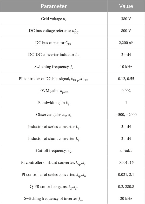
The effectiveness of the voltage compensation control strategy is verified under different test conditions. The system model is built in the MATLAB/Simulink simulation environment. System parameters are presented in Table 1.
4.1 System performance with nonlinear loads
To verify the effectiveness of the proposed scheme, the nonlinear loads are applied to the system for the simulation test. The dynamic results of the UPQC with nonlinear loads are depicted in Figure 7. As shown in Figure 7A, the load voltage is 310.17 V. It can be seen that the proposed voltage compensation strategy achieves voltage vector compensation by the series converter. Figures 7B and G display the dynamic results of the grid voltages and grid currents. It is observed that the phase of the grid voltage is the same as that of the grid current. By the current compensation of the parallel converter, the output waveforms maintain smooth sinusoidal characteristics. Furthermore, the NDO guarantees the stabilization of the DC bus voltage under the condition of the current disturbance. It reveals that the proposed method realizes the comprehensive management of voltage quality and ensures the stability of DC bus voltage.
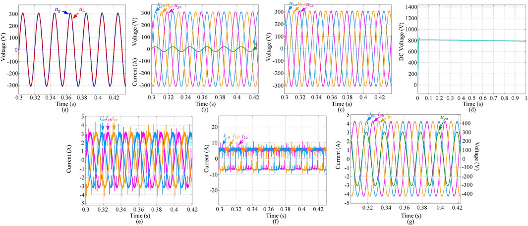
Figure 7. Dynamic results with nonlinear loads. (A) Grid voltage
4.2 System performance with load change
To test the dynamic performance of the system, a simulation case is conducted considering load change. The dynamic results of the UPQC with load change are displayed in Figure 8. At
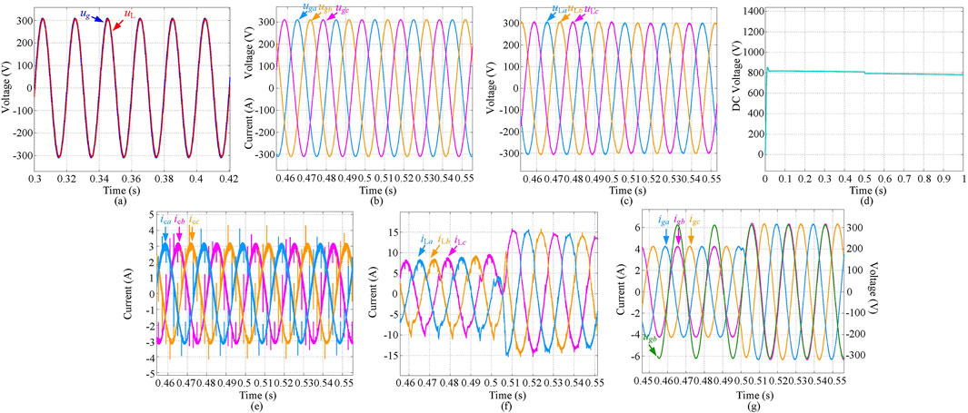
Figure 8. Dynamic results with load change. (A) Grid voltage
4.3 System performance under voltage sag and swell
Figures 9, 10 present the system dynamic results when the system encounters voltage sag and voltage swell. To validate the proposed control strategy, at
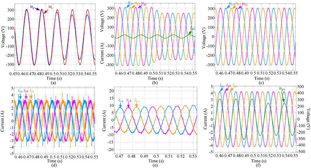
Figure 9. Dynamic results under voltage sag (20%). (A) Grid voltage

Figure 10. Dynamic results under voltage swell (10%). (A) Grid voltage
5 Conclusion
In this paper, a voltage compensation control strategy was proposed for the distribution network to achieve comprehensive management of power quality. To compensate for the amplitude and phase of the load voltage, a capacity configuration compensation scheme was proposed, which realizes the capacity configuration among parallel converter, series converter, and BESS. An NDO was designed to implement the current disturbance tracking and achieve disturbance compensation by a feedforward channel. Then, an NDO-based voltage control approach was developed for BESS to guarantee the stabilization of the DC bus voltage and improve the response speed of DC voltage. Simulation results demonstrated that the proposed control strategy effectively mitigated voltage sags and swells, significantly enhanced the dynamic response, and improved the overall stability and reliability of the distribution network, which highlighted the effectiveness of the integration of UPQC with BESS in managing power quality and enhancing system responsiveness. Future research will focus on robust cyber security measures to protect the grid from potential cyber threats and ensure the integrity of the control systems, combined with advanced control systems and energy storage technologies.
Data availability statement
The original contributions presented in the study are included in the article/supplementary material, further inquiries can be directed to the corresponding author.
Author contributions
YM: Writing–original draft, Writing–review and editing. JX: Writing–original draft, Writing–review and editing. CP: Writing–original draft, Writing–review and editing. WK: Writing–original draft, Writing–review and editing. GP: Writing–original draft, Writing–review and editing. GS: Writing–original draft, Writing–review and editing.
Funding
The author(s) declare that financial support was received for the research, authorship, and/or publication of this article. This work was supported in part by the Science and Technology Project of State Grid Xizang Electric Power Co., Ltd. (523101230003).
Conflict of interest
Authors YM, JX, CP, WK, GP, and GS were employed by Electric Power Research Institute of State Grid Xizang Electric Power Co., Ltd.
The authors declare that this study received funding from Electric Power Research Institute of State Grid Xizang Electric Power Co., Ltd. The funder had the following involvement in the study: collection, interpretation of data, the writing of this article, and the decision to submit it for publication.
Publisher’s note
All claims expressed in this article are solely those of the authors and do not necessarily represent those of their affiliated organizations, or those of the publisher, the editors and the reviewers. Any product that may be evaluated in this article, or claim that may be made by its manufacturer, is not guaranteed or endorsed by the publisher.
References
Abdalaal, R. M., and Ho, C. N. M. (2021). Analysis and validations of modularized distributed TL-UPQC systems with supervisory remote management system. IEEE Trans. Smart Grid 12 (3), 2638–2651. doi:10.1109/tsg.2020.3044992
Abdalaal, R. M., and Ho, C. N. M. (2022). System modeling and stability analysis of single-phase transformerless UPQC integrated input grid voltage regulation. IEEE J. Emerg. Sel. Top. Power Electron. 3 (3), 670–682. doi:10.1109/jestie.2021.3091395
Alcala, J. M., Castilla, M., De Vicuña, L. G., Miret, J., and Vasquez, J. C. (2010). Virtual impedance loop for droop-controlled single-phase parallel inverters using a second-order general-integrator scheme. IEEE Trans. Power Electron. 25 (12), 2993–3002. doi:10.1109/tpel.2010.2082003
Bacon, V. D., da Silva, S. A. O., and Guerrero, J. M. (2022). Multifunctional UPQC operating as an interface converter between hybrid AC-DC microgrids and utility grids, Int. J. Electr. Power & Energy Syst. 136 (3), 1–19. doi:10.1016/j.ijepes.2021.107638
Cardoso, J. T., Felinto, A. S., Jacobina, C. B., and Corrêa, M. B. d. R. (2024). Three-phase four-wire nine-leg AC-DC-AC converter based on high-frequency link. IEEE Trans. Power Electron. 39 (1), 885–897. doi:10.1109/tpel.2023.3327160
Carreno, A., Perez, M. A., and Malinowski, M. (2024). State-feedback control of a hybrid distribution transformer for power quality improvement of a distribution grid. IEEE Trans. Ind. Electron. 71 (2), 1147–1157. doi:10.1109/tie.2023.3262872
Çelik, D., and Ahmed, H. (2023). Enhanced control of superconducting magnetic energy storage integrated UPQC for power quality improvement in EV charging station. J. Energy Storage 62, 106843. doi:10.1016/j.est.2023.106843
Charalambous, A., Hadjidemetriou, L., Kyriakides, E., and Polycarpou, M. M. (2021). A coordinated voltage-frequency support scheme for storage systems connected to distribution grids. IEEE Trans. Power Electron. 36 (7), 8464–8475. doi:10.1109/tpel.2020.3046030
Dash, S. K., and Ray, P. K. (2021). A new PV-open-UPQC configuration for voltage sensitive loads utilizing novel adaptive controllers. IEEE Trans. Ind. Inf. 17 (1), 421–429. doi:10.1109/tii.2020.2986308
da Silva, S. A. O., Campanhol, L. B. G., Pelz, G. M., and de Souza, V. (2020). Comparative performance analysis involving a three-phase UPQC operating with conventional and dual/inverted power-line conditioning strategies. IEEE Trans. Power Electron. 35 (11), 11652–11665. doi:10.1109/tpel.2020.2985322
Devassy, S., and Singh, B. (2021). Performance analysis of solar PV array and battery integrated unified power quality conditioner for microgrid systems. IEEE Trans. Ind. Electron. 68 (5), 4027–4035. doi:10.1109/tie.2020.2984439
Felinto, A. S., Cunha, M. F., and Jacobina, C. B. (2022). Three-phase unified power quality conditioner based on high-frequency link. IEEE Trans. Ind. Appl. 58 (5), 6397–6407. doi:10.1109/tia.2022.3188599
Hosseini, M. M., and Parvania, M. (2023). Hierarchical intelligent operation of energy storage systems in power distribution grids. IEEE Trans. Sustain. Energy 14 (2), 741–750. doi:10.1109/tste.2022.3222425
Jin, T., Chen, Y., Guo, J., Wang, M., and Mohamed, M. A. (2020). An effective compensation control strategy for power quality enhancement of unified power quality conditioner. Energy Rep. 6, 2167–2179. doi:10.1016/j.egyr.2020.07.027
Khosravi, N., Echalih, S., Hekss, Z., Baghbanzadeh, R., Messaoudi, M., and Shahideipour, M. (2023). A new approach to enhance the operation of M-UPQC proportional-integral multiresonant controller based on the optimization methods for a stand-alone AC microgrid. IEEE Trans. Power Electron. 38 (3), 3765–3774. doi:10.1109/tpel.2022.3217964
Li, Z., Wu, L., Xu, Y., Wang, L., and Yang, N. (2023). Distributed tri-layer risk-averse stochastic game approach for energy trading among multi-energy microgrids. Appl. Energy 331, 120282. doi:10.1016/j.apenergy.2022.120282
Li, Z., Xu, Y., Wang, P., and Xiao, G. (2024). Restoration of a multi-energy distribution system with joint district network reconfiguration via distributed stochastic programming. IEEE Trans. Smart Grid 15 (3), 2667–2680. doi:10.1109/tsg.2023.3317780
Lou, G., Yang, Q., Gu, W., Quan, X., Guerrero, J., and Li, S. (2021). Analysis and design of hybrid harmonic suppression scheme for VSG considering nonlinear loads and distorted grid. IEEE Trans. Energy Convers. 36 (4), 3096–3107. doi:10.1109/tec.2021.3063607
Mahela, O. P., Khan, B., Alhelou, H. H., and Siano, P. (2020). Power quality assessment and event detection in distribution network with wind energy penetration using stockwell transform and fuzzy clustering. IEEE Trans. Ind. Inf. 16 (11), 6922–6932. doi:10.1109/tii.2020.2971709
Monteiro, V., Moreira, C., Lopes, J. A. P., Antunes, C. H., Osório, G. J., Catalão, J. P. S., et al. (2024). A novel three-phase multiobjective unified power quality conditioner. IEEE Trans. Ind. Electron. 71 (1), 59–70. doi:10.1109/tie.2023.3241380
Ray, P., Ray, P. K., and Dash, S. K. (2022). Power quality enhancement and power flow analysis of a PV integrated UPQC system in a distribution network. IEEE Trans. Ind. Appl. 58 (1), 201–211. doi:10.1109/tia.2021.3131404
Sanjenbam, C. D., Singh, B., and Shah, P. (2023). Reduced voltage sensors based upqc tied solar PV system enabling power quality improvement. IEEE Trans. Energy Convers. 38 (1), 392–403. doi:10.1109/tec.2022.3197408
Silva, S. A. O. D., Modesto, R. A., Sampaio, L. P., and Campanhol, L. B. G. (2024). Dynamic improvement of a UPQC system operating under grid voltage sag/swell disturbances. IEEE Trans. Circuits Syst. II 71 (5), 2844–2848. doi:10.1109/tcsii.2023.3263068
Somayajula, D., and Crow, M. L. (2014). An ultracapacitor integrated power conditioner for intermittency smoothing and improving power quality of distribution grid. IEEE Trans. Sustain. Energy 5 (4), 1145–1155. doi:10.1109/tste.2014.2334622
Song, G., Liu, X., Xiao, G., Chen, B., and Wang, P. (2024b). Decentralized adaptive control strategy of DC-DC boost converter for hybrid energy storage systems feeding CPLs. IEEE J. Emerg. Sel. Top. Power Electron. 12 (4), 3663–3674. doi:10.1109/jestpe.2024.3403000
Song, G., Liu, X., Xiao, G., Xiong, L., Chen, B., Wang, P., et al. (2024a). Circulating current suppression of power conversion systems under unbalanced conditions: large-signal model-based analysis. CPSS Trans. Power Electron. Appl. 9 (2), 152–165. doi:10.24295/cpsstpea.2023.00051
Tziovani, L., Hadjidemetriou, L., Kolios, P., Astolfi, A., Kyriakides, E., and Timotheou, S. (2022). Energy management and control of photovoltaic and storage systems in active distribution grids. IEEE Trans. Power Syst. 37 (3), 1956–1968. doi:10.1109/tpwrs.2021.3118785
Wang, H., Yan, Z., Shahidehpour, M., Zhou, Q., and Xu, X. (2021b). Optimal energy storage allocation for mitigating the unbalance in active distribution network via uncertainty quantification. IEEE Trans. Sustain. Energy 12 (1), 303–313. doi:10.1109/tste.2020.2992960
Wang, J., Sun, K., Wu, H., Zhu, J., Xing, Y., and Li, Y. (2021a). Hybrid connected unified power quality conditioner integrating distributed generation with reduced power capacity and enhanced conversion efficiency. IEEE Trans. Ind. Electron. 68 (12), 12340–12352. doi:10.1109/tie.2020.3040687
Xu, W., Zhu, W., and Shu, Z. (2023). Suppression of DC voltage ripple impact on non-isolated single-phase half-bridge unified power quality conditioner. IEEE Trans. Ind. Electron. 71, 10523–10532. doi:10.1109/TIE.2023.3337497
Yang, R., Jin, J., Zhou, Q., Mu, S., and Abu-Siada, A. (2022b). Superconducting magnetic energy storage based dc unified power quality conditioner with advanced dual control for DC-DFIG. J. Mod. Power Syst. Clean. Energy 10 (5), 1385–1400. doi:10.35833/mpce.2021.000354
Yang, R. H., and Jin, J. X. (2021). Unified power quality conditioner with advanced dual control for performance improvement of DFIG-based wind farm. IEEE Trans. Sustain. Energy 12 (1), 116–126. doi:10.1109/tste.2020.2985161
Yang, R. H., Jin, J. X., Mu, S., Zhang, M. S., Jiang, S., Chen, X. Y., et al. (2022a). Battery-energy-storage-based triple-active-bridge DC unified power quality conditioner for energy management and power quality enhancement of DC renewable sources, Int. J. Electr. Power & Energy Syst. 143 (4), 108442. doi:10.1016/j.ijepes.2022.108442
Keywords: distribution network, power quality, unified power quality conditioner, battery energy storage systems, nonlinear disturbance observer
Citation: Mei Y, Xu J, Peng C, Kong W, Peng G and Song G (2024) Voltage quality enhancement of distribution network based on unified power quality conditioner with BESS. Front. Energy Res. 12:1472503. doi: 10.3389/fenrg.2024.1472503
Received: 29 July 2024; Accepted: 29 August 2024;
Published: 16 September 2024.
Edited by:
Zhengmao Li, Aalto University, FinlandReviewed by:
Xiang Gao, Xi’an University of Technology, ChinaMing-Feng Ge, China University of Geosciences Wuhan, China
Wentao Jiang, Northwestern Polytechnical University, China
Copyright © 2024 Mei, Xu, Peng, Kong, Peng and Song. This is an open-access article distributed under the terms of the Creative Commons Attribution License (CC BY). The use, distribution or reproduction in other forums is permitted, provided the original author(s) and the copyright owner(s) are credited and that the original publication in this journal is cited, in accordance with accepted academic practice. No use, distribution or reproduction is permitted which does not comply with these terms.
*Correspondence: Guangyu Song, c29uZ2d5XzFAMTI2LmNvbQ==
 Yan Mei
 Guangyu Song