 Kunte Abhijit Bhagwan
 Udaya Bhasker Manthati
 Faisal Alsaif
- 1Department of Electrical Engineering, National Institute of Technology-Warangal, Warangal, Telangana, India
- 2Department of Electrical Engineering, College of Engineering, King Saud University, Riyadh, Saudi Arabia
This work presents a system design for extracting maximum power using the modified maximum power point tracking (MPPT) technique and a novel high-gain DC-DC converter, which was then used to supply a microgrid system with a conventional buck converter. We present a novel structure comprising the MPPT, voltage boosting, and voltage regulating components for a DC microgrid in a single system. The most important features of a photovoltaic (PV) system include a high-gain converter and maximum PV power extraction; considering these, we present a high-gain DC-DC converter that boosts the output voltage to ten times the input voltage. Furthermore, the MPPT technique extracts maximum power from the PV panel based on model predictive control through its better transient response than the conventional incremental conductance method. The MPPT approach was tested with both fixed- and variable-step operations, and the results were compared for load variations. Considering the economics of the system, the proposed approach attempts cost reduction by optimizing the number of sensors to two instead of three. Simulations were conducted under different environmental conditions using MATLAB-Simulink, and the performance differences between the conventional incremental conductance and proposed MPPT-based methods are shown. Next, DC voltage regulation was implemented for the proposed PV and existing systems by considering different load and irradiation conditions while maintaining constant temperature. The simulation results showed the latter system had better performance than the former under different environmental conditions, with persistent results for voltage regulation at different load and irradiation conditions.
1 Introduction
Solar power is a universal energy source that has stochastic behaviors and varies with the intensity of natural light. Solar power generation entails different components, such as the type of cell, irradiation, temperature, size, and environmental conditions. Solar panels and DC-DC high-gain converters play vital roles in injecting power into a DC microgrid. The traditional maximum power point tracking (MPPT) technique involves finding a point on a voltage vs. current plot at which maximum power can be extracted under the given environmental conditions. There are several reported MPPT techniques in literature, such as the perturb and observe (P&O) method and incremental conductance (IC) method (Ram et al., 2017; Bollipo et al., 2020a; Kumar et al., 2023; Bollipo et al., 2020b). These methods are differentiated from each other based on the accuracy of maximum power tracking as well as its implementation in a photovoltaic (PV) system, algorithmic complexity, and measured variables. However, one of the main drawbacks of the P&O method is the failure to adapt to instantaneously changing conditions and power loss due to the constantly introduced perturbation changes; furthermore, this method is affected by oscillations when operating at the maximum power point (MPP) (Bollipo et al., 2020a; Mei et al., 2011; Jiang et al., 2013).
With regard to DC-DC converters, the conventional boost converter suffers from instability under practical conditions, particularly after experiencing higher duty cycles (Fang et al., 2019; Liu et al., 2019; Basha and Rani, 2020; Tarzamni et al., 2023). Different conversion techniques have been noted and compared in Forouzesh et al. (2017), Xu et al. (2020) along with brief details on their applications to boost the input voltage to the level required for a microgrid. Switched inductors/capacitors can also be used to boost the input voltage by 2–3 times maximally without using higher duty cycles. Fang et al. (2019) described a cascaded boost converter to amplify the input voltage using a low duty cycle. Forouzesh et al. (2017) and Kumar et al. (2020) showed that the quadratic boost converter provides a higher step-up ratio than the switched inductor/capacitor with a higher current stress on its power switch; this stress on the switch deteriorates the efficiency of the converter.
Another important consideration is the maximum power tracking technique. As mentioned earlier, the P&O method suffers from oscillation at the MPP. To counter this problem, Abdel-Salam et al. (2020) proposed an improved approach called delta P&O and adaptive step-change method. MPPT without a current sensor was proposed by Metry and Balog (2020), where the PV current can be calculated from a prespecified look-up table using PV voltage measurements and cell temperature estimates; however, this technique suffers from complexity and reliability problems owing to difficulties with ambient temperature estimation and dynamic model accuracy of the system involving multiple variables.
In systems that require multivariable control, finite-set model predictive control (FS-MPC) is a desirable solution (Ferreira et al., 2018). MPC-based MPPT has been reported in literature (Abdel-Rahim and Wang, 2020; Xue et al., 2022), and the MPC-based MPPT methodology presented by Ferreira et al. (2018) can track the maximum power of a PV module efficiently under various environmental conditions. However, this scheme uses three sensors, namely, two voltage and one current sensors, thereby incurring a higher cost.
The third aspect of this study is regarding voltage regulation. The primary function of a boost converter is extracting the maximum power at a particular duty cycle and voltage. However, when this extracted power is meant to be injected into another application or a grid, it is necessary to modulate its voltage accordingly. To inject the generated PV power into a grid with high quality and improve the PV system efficiency, it is crucial to achieve MPPT of the PV system along with voltage regulation. Unfortunately, most studies focus on only one of these aspects, i.e., MPPT or voltage regulation, instead of addressing both simultaneously (Lupangu and Bansal, 2017). Thus, few researchers have explored two-level control where voltage regulation and MPPT are discussed together, as in Ma et al. (2020). In Ma et al. (2020), the authors explain a two-stage converter with cascaded boost and buck operations to provide maximum power extraction as well as voltage regulation.
To achieve voltage regulation, related control methods are studied often, such as proportional–integral–differential (PID) control (Sunddararaj et al., 2021), fuzzy logic control (Kart et al., 2024), feedback linearization control (Sharma and Suhag, 2020), and sliding-mode control (Al-Wesabi et al., 2022; Xie et al., 2020), and hybrid control (Ibrahim et al., 2024; Suthar et al., 2024; Rafikiran and Alsaif, 2024). In the present work, a novel model predictive controller that is more efficient than other methods is employed in a high-gain DC-DC converter for a PV power system (Figure 1). Accurate mathematical modeling is required and developed for its implementation under varying load conditions.
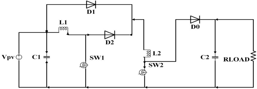
Figure 1. Novel high-gain DC-DC converter circuit for photovoltaic (PV) systems.
2 Proposed topology
The main objectives of the proposed work are as follows:
1. Implementation of proposed step-up converter topology for solar applications.
2. Implementation of MPC-based MPPT through the IC method.
3. Verifications of the topology and control strategy performances under different environmental conditions.
4. Verifications of the topology and control strategy performances for fixed-step and variable-step changes.
5. Comparison of MPPT for the IC and proposed methods.
6. Voltage regulation of the proposed PV system through a two-stage grid-tied system.
The two-stage grid-tied converter topology structure is considered for the control of the PV system in this work. The first-stage converter matches the output and load impedances and tracks the MPP, while the second-stage converter regulates the output voltage to the desired value.
This converter comprises two inductors that are switched using two switches, i.e., MOSFET power switches with three diodes, which help define the different modes of operation. Additionally, two capacitors placed one each on the input and output sides act as filters to ensure fewer voltage ripples. When this converter is operated in continuous mode, then are two operating modes defined by S = 1 and 0 for the switch ON and OFF conditions, respectively.
Mode-I Operation (SW1 = SW2 = 1): When switches S1 and S2 are both turned on, the inductors L1 and L2 are charged by the supply voltage. This leads to a condition where diodes D1 and D0 remain turned off, as shown in Figure 2. Applying Kirchhoff’s law to this circuit, we have
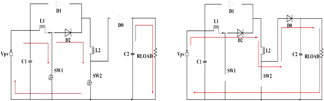
Figure 2. Mode-I and Mode-II operations of the high-gain DC-DC converter.
Mode-II Operation (SW1 = SW2 = 0): When switches S1 and S2 are both turned off, the inductors start discharging to the load alongside the supply voltage. In this condition, diodes D2 and D0 are turned on to provide a path to load while D1 is turned off, as shown in Figure 2.
Based on the analyses in Modes I and II as well as application of inductor volt-second balance and charge balance to the equations obtained from the two modes of operation, the input–output relationship is further derived.
Following the above analyses, the input and output relationship is obtained as
Then, the parameters of the high-gain converter are defined, and their values are set based on how much ripple can be tolerated.
2.1 Inductor design
There are two inductors in the proposed converter, and both of these are symmetric and identical. To determine the inductor values, the current waveforms over one period are considered and equations are derived using the input voltage, duty cycle, inductor current ripple, and sample time (Ts).
2.2 Capacitor design
From the waveform shown in Figure 3(ii) and the above derivations, the capacitor values are obtained using the duty cycle, output voltage, sample time, and capacitor voltage ripple.
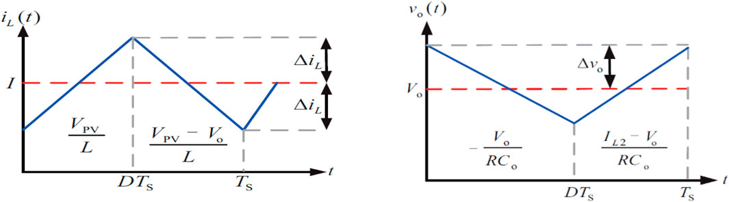
Figure 3. Waveforms of (i) current through the inductor and (ii) output voltage.
The output capacitor is designed by considering the output voltage waveform over one period and the expression for voltage ripple derived above.
3 Different MPPT techniques
There are many MPPT techniques in literature for extracting the maximum power values efficiently from PV panels using different types of converters. These converters act as interfaces between the PV system and load or grid. There are two types of algorithms for MPPT (Figure 4), where the first involves changing the duty cycle for optimization and the second uses the voltage or current reference from MPPT along with different control techniques for optimization.
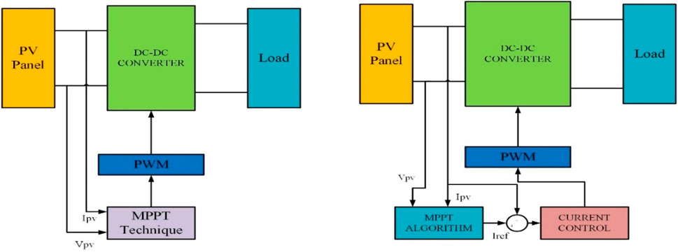
Figure 4. Different methods of implementing the proposed maximum power point tracking (MPPT) technique.
The different MPPT techniques available include the P&O, IC, artificial neural network, and open-circuit voltage methods, among others; all of these techniques can be compared in terms of hardware, algorithm complexity, and use as standalone or integrated systems. However, among these techniques, the P&O and IC methods are used commonly even though they are inefficient and expensive, respectively.
3.1 Proposed MPPT technique
The proposed method involves predictive control and is mainly characterized by use of the system model to predict the future values of the controllable variables. Using this information on the future values, optimal actuation is achieved as per the predefined criteria. The main advantages of predictive control are its intuitive nature and simple concepts; as predictive control schemes avoid cascaded structures for linearization, they provide quick transient responses. Moreover, the system can include model non-linearities for improved operation under all conditions. MPC is implemented using the following steps:
Step 1: The system model is defined and used to predict the future behaviors of the variables up to the time horizon.
Step 2: The cost function is defined in terms of the desired behaviors of the system.
Step 3: Once the cost function is defined, the discrete model of the system is derived by predicting the future behaviors of the controlled variables.
Step 4: The system optimizes the performance by minimizing the value of the cost function.
Figure 5 shows the block diagrams for voltage regulation of the PV system and MPC implementation. The basic definition of the cost function is the error between the reference and predicted values of the quantity to be controlled. These quantities include the load current, load torque, and speed; sometimes, these quantities are multiplied by a weighting factor according to their importance.
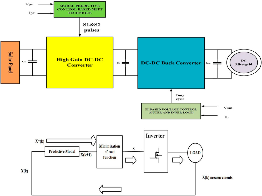
Figure 5. Block diagrams of (i) voltage regulation of the PV system and (ii) model predictive control (MPC) implementation.
Given the discrete prediction model of the form
the cost function can be written as
This equation considers the references, future states, and future actions, and the system control is based on minimizing the cost function J. Here, N is the predefined horizon time within which the control actions are implemented. Further constraints and weighting factors can be added to the system as per the control requirement. With the inclusion of weighting factors, the cost function can be written as below for current control of a neutral point converter.
Here, i represents the α and β component currents,
3.2 MPC-based MPPT
MPC is a type of regulation that depends on the parameters of the DC-DC converter. It treats the DC-DC converter as a finite set of linear models, where each model represents the switching states. These switching states are calculated using MPC, resulting in minimization of the cost function. Reducing the cost simply means that the errors in the controllable variables are reduced. Then, these switching states of the minimized cost function are applied to the DC-DC converter. When operating this converter, the system works in the continuous mode with two state variables. A discrete model is then developed using the forward Euler method for the on and off state operation equations. These discrete model equations are as follows:
where I1PV(K+1) and I0PV(K+1) are the predicted values of the PV current during the on and off states, respectively; VPV and V0 are the PV and output voltages, respectively; Ts is the sampling time; L is an inductor representing both L1 and L2, which are equal.
As noted earlier for the types of algorithms used for MPPT, the first type is used for optimization. Here, the reference current is obtained using the conventional IC method, and MPC is used to generate the predicted values of the controllable variables. Figure 6 depicts the basic scheme of the control algorithm that uses the adaptive IC and prediction blocks based on Equations 2, 3 to generate the reference and next-step PV currents, respectively. The third block is an optimization step that generates switching pulses such that the difference between the two currents is minimized, which is simply the optimization of the cost function. From Equations 2, 3, it is clear that three quantities must be sensed, namely Vpv, Ipv, and Vout, to determine the predictive values of the PV currents. However, Equation 1 can be used as a voltage observer to calculate the output voltage using Vpv and duty cycle data; this reduces the number of sensors to two, which in turn reduces the cost of the system.
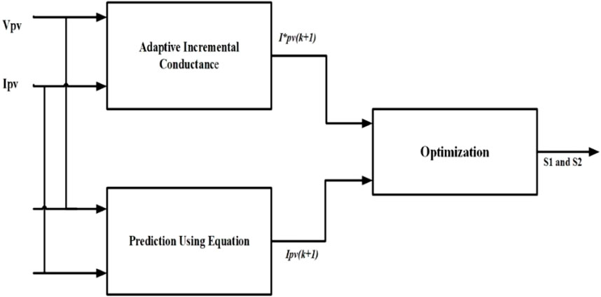
Figure 6. Block diagram of implementation of the MPC-based MPPT technique.
The next step in MPC is optimization, where the possible future states can be used to optimize and select the optimum values that minimize the error. The cost function is used for optimization and is given by
where g is the cost function, Iref is the reference current, and IαPV is the PV current. The current reference Iref is generated using the IC method. The pictorial description of the overall process for the fixed-step and variable-step operations is presented in Figure 7.
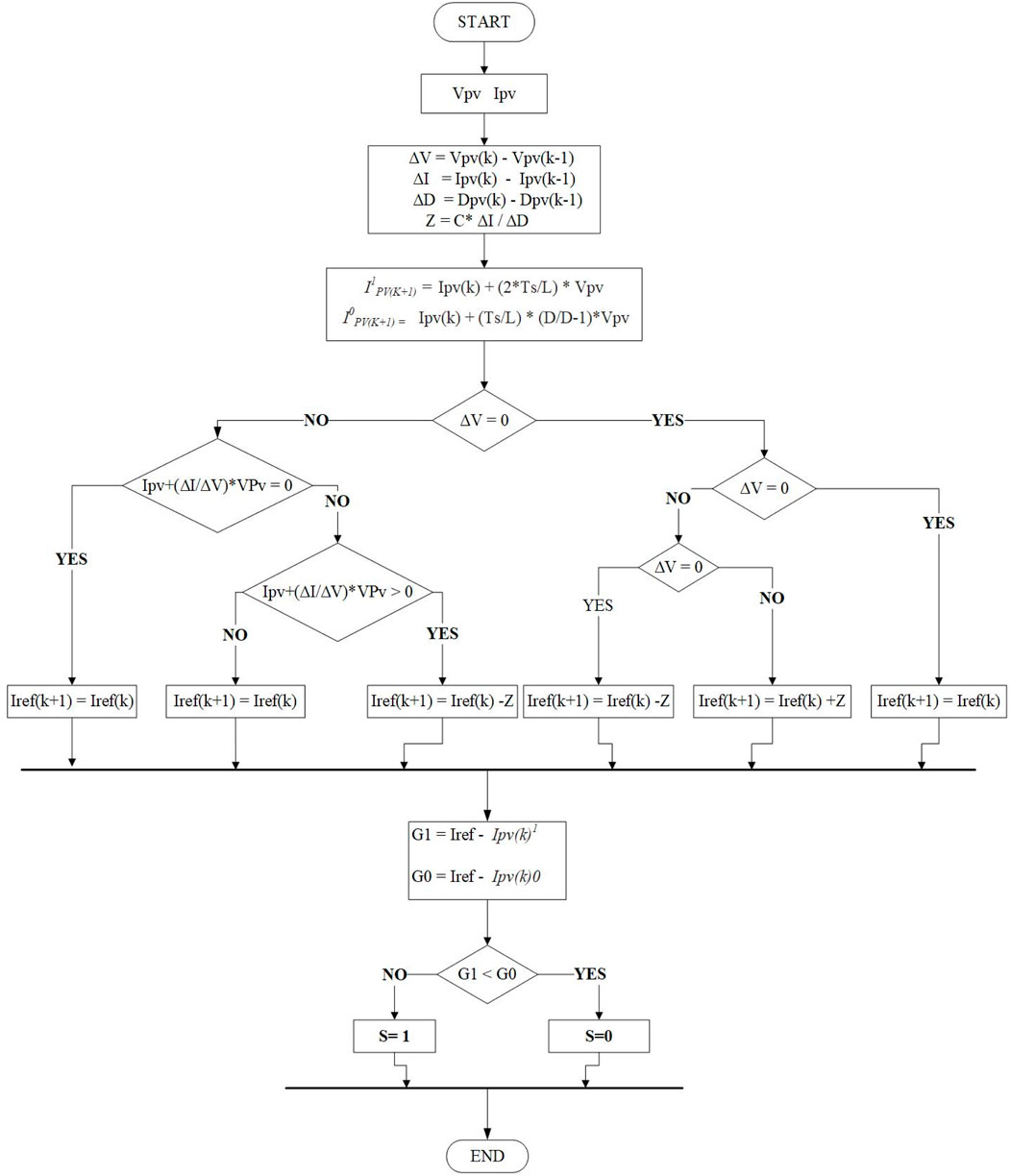
Figure 7. Flowchart of the algorithm for MPC-based MPPT.
In the MPC-based MPPT algorithm, the first step involves sensing Ipv and Vpv. Next, the conventional IC method is used to generate the reference current. Through this algorithm, the converter starts tracking the maximum power. The perturbation size Z shown in the flow chart is fixed or adaptive and is given by
Here, C is scaling factor,
4 Voltage regulation of the proposed PV system for microgrid application
Previously, the novel high-gain DC-DC converter and MPPT technique were explained; accordingly, the next step involves extending the proposed method by adding a DC-DC buck converter to regulate the PV system voltage to the required bus output voltage that can be maintained under time-varying irradiation and variable-load conditions. This overall structure is a two-stage grid-tied converter.
The development of renewable energy sources like solar energy as widespread and clean sources has attracted immense amounts of scientific and industrial interest in recent years. The applications of distributed PV systems and DC microgrids have increased the utilization of solar energy. Meanwhile, advancements in power electronic technologies have further extended the research boundaries of PV systems and improved the efficiency of energy conversion. However, rapid changes in environmental conditions still affect the efficiency and stability of PV systems. In addition, to inject the generated PV power into a grid with high quality, the output voltage of the PV system needs to be regulated. Hence, PV systems must be robust to MPPT and output voltage regulation. The circuit diagram for voltage regulation of the proposed system is shown in Figure 8.
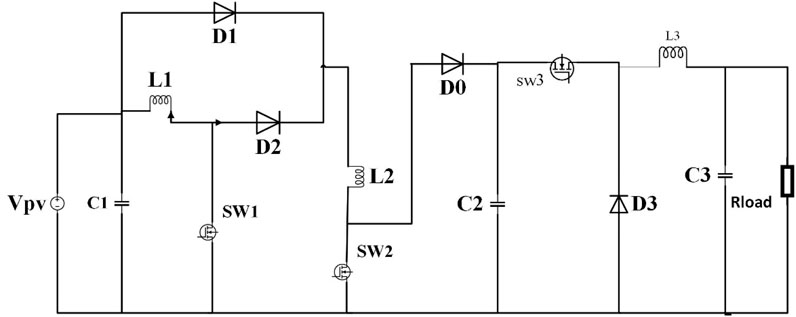
Figure 8. DC-DC buck converter circuit for voltage regulation of the PV system.
4.1 Design of the DC-DC buck converter
When designing the buck converter, some parameters like the output voltage and current of the high-gain DC-DC converter are assumed to be bound within particular ranges. The output voltage of the buck converter is optimized to the bus voltage using PI control of a specific load (resistive). After considering all the parameters, the operation is regarded to be continuous mode. The conventional formulas of the inductor current and output voltage ripples are used to calculate the values of the inductors and capacitors. These are given by the following equations.
To find the inductor value, we consider
To find the output capacitor value, we consider
4.2 PI-based voltage regulation
The control scheme for output voltage regulation of the PV system is as follows. When designing the control loop, two levels of loops are considered. First, the PI controller in the inner loop is designed to satisfy the high-frequency switching action. Then, the outer loop is designed to improve the dynamic performance of the DC-DC buck converter. The state-space model is required for the control analysis, where the state vector is given by
where i is the inductor current and v is the capacitor voltage. This results in two possible matrices depending on whether the switch is on or off. The switch state is given by the subscript j, which is set to 1 when the control is on and 2 when the control is off. The state equation of the DC-DC buck converter is given by
where
Using the averaging method, we have
4.2.1 Outer loop design
The outer loop is the voltage control loop, whose reference voltage is the bus voltage. The PI control law for voltage can be written as
4.2.2 Inner loop design
The inner loop is the current control loop that is managed by the PI controller; here, the reference current is generated using the outer loop. The PI control law for current can be written as
The values of the constants are found by trial and error methods for both loops.
5 Results and discussion
The simulation results are primarily divided into three parts as follows: open-loop operation of the high-gain DC-DC converter; application of the high-gain DC-DC converter to the PV system; voltage regulation of the PV system using the DC-DC buck converter. All the parameter ratings used in the simulations are shown in Table 1.
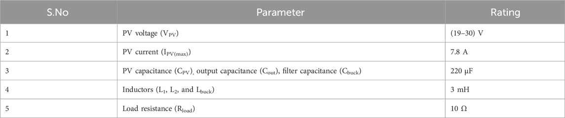
Table 1. Parameters and ratings.
5.1 Open-loop operation
The high-gain DC-DC converter was simulated in MATLAB 2016 and designed to boost the input voltage by 10 times. It can operate at an efficiency of around 93%.
Figure 9 shows the schematic for the simulation of the open-loop operation of the high-gain DC-DC converter at a duty cycle of 0.65. Analytically, the circuit is shown to boost the input voltage by up to 4.71 times. The magnified output voltage signal is shown in Figure 10, where the load resistance is observed to be approximately 10 Ω.
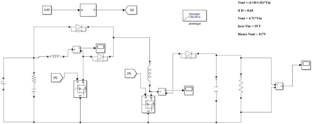
Figure 9. Open-loop simulation of the high-gain DC-DC converter.
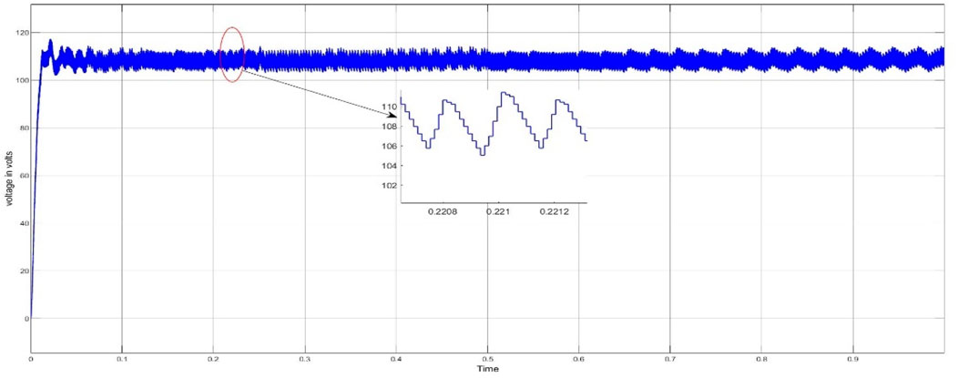
Figure 10. Output voltage of the high-gain DC-DC converter.
5.2 Application of high-gain DC-DC converter and MPC-based MPPT to PV systems
Herein, we demonstrate the application of the new MPC-based MPPT technique to a PV system based on the operation type as fixed or variable step. Additionally, the output power comparison is presented.
5.2.1 Fixed-step operation
The PV panel used in the simulation is inbuilt and present in the simulation library under the name “1soltech-1STH-215-P”. The inputs to this block were the temperature and irradiation, which were set to 25°C and 1,000 W/m2, respectively. The schematic of this simulation is depicted in Figure 11. This operation configuration is mostly concerned with power drawn using MPPT, but the system has a novel DC-DC converter that boosts the input voltage efficiently. The duty cycle was set as 0.65. Figure 12 shows the input and output power trends for the fixed-step operation, while Figure 13 shows the input and output voltage trends under this configuration.
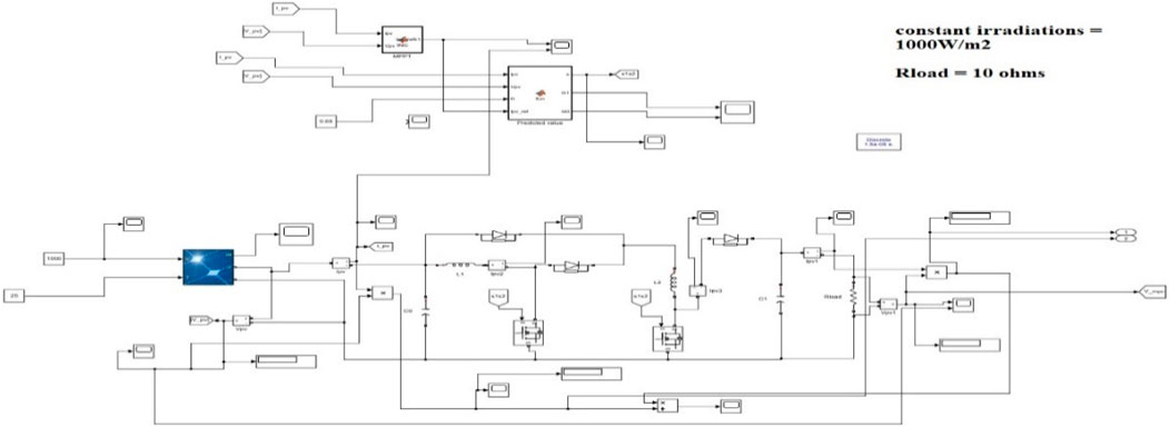
Figure 11. Fixed-step operation of the high-gain DC-DC converter of the PV system.
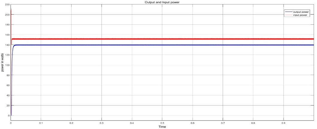
Figure 12. Output and input power values for fixed-step operation.
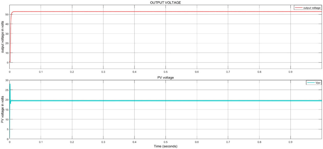
Figure 13. Output and input voltages for fixed-step operation.
The parameters are designed with respect to the inductor current shown in Figure 14 for the fixed-step operation. A magnified portion of this curve is highlighted by the red circle. Next, we examined the system response to variation in irradiation from 1,000 W/m2 to 800 W/m2 under fixed-step operation; these results are shown in Figure 15. Under fixed-step operation, the output power of the system is approximately 138–140 W; if this system were to be implemented under variable-step operation, there would be flexibility in choosing the step size as per requirement. This flexibility allows the system to produce more output power.

Figure 14. Inductor current during fixed-step operation.
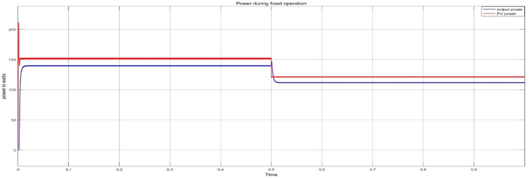
Figure 15. Change in the output power as the irradiation changes from 1,000 W/m2 to 800 W/m2 at t = 0.5 s.
5.2.2 Variable-step operation
As explained earlier, variable-step operation offers more flexibility and superior performance to fixed-step operation. The parameters are considered in this configuration are similar to those used previously. Figure 16 shows the schematic for variable-step operation under a constant temperature of 25°C and irradiation of 1,000 W/m2 (Figure 17). The variable-step operations under a change in irradiation from 1,000 W/m2 to 800 W/m2 are shown in Figure 18.
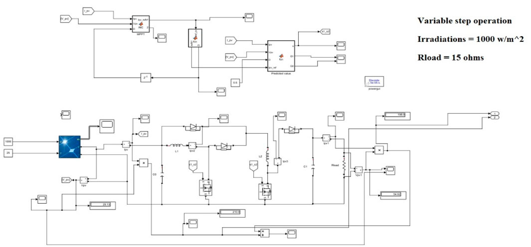
Figure 16. Simulation of the variable-step operation of the PV system.
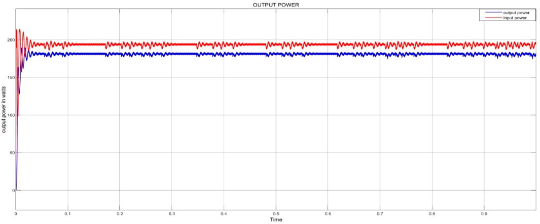
Figure 17. Output power of the variable-step operation under constant temperature and irradiation.
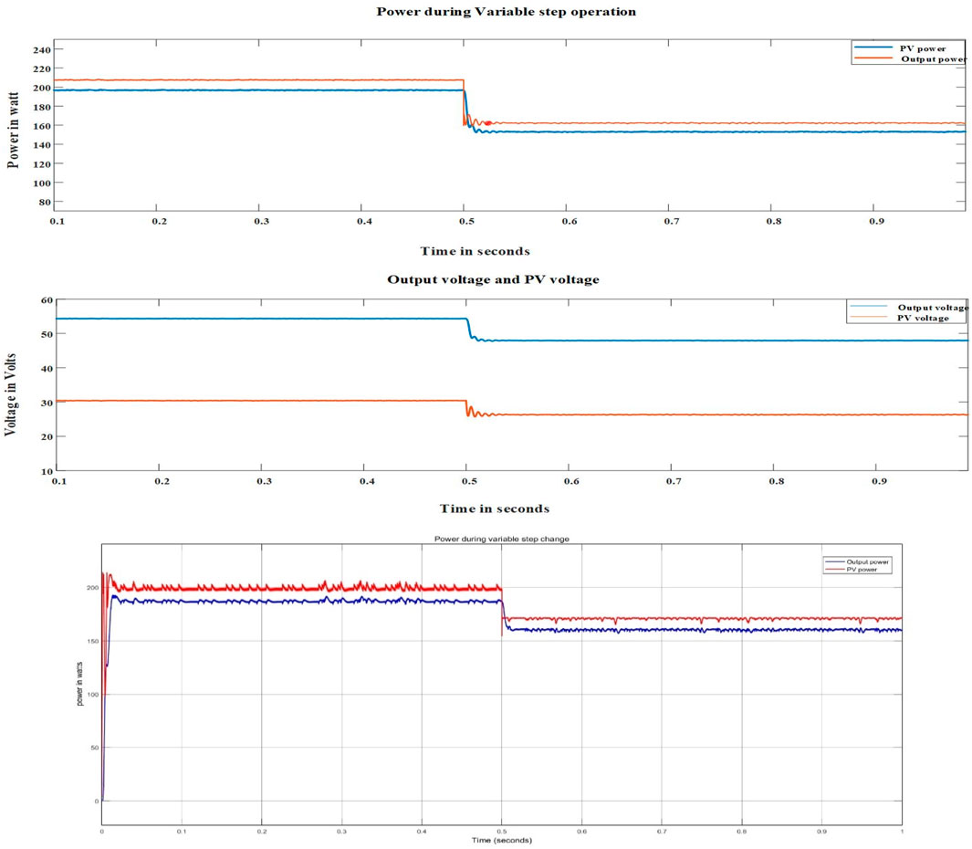
Figure 18. (i) Output responses for variable-step operation with change in irradiation at t = 0.5 s. (ii) Output power during variable-step operation with change in irradiation at t = 0.5 s.
5.3 Voltage regulation of the proposed PV system
The main principle of regulating the output voltage of a high-gain DC-DC converter is to supply the excess available power to different applications through a DC microgrid. To regulate the voltage, a two-stage converter was developed, where the first stage was the high-gain DC-DC converter and the second stage was a cascaded buck converter (Figure 19).
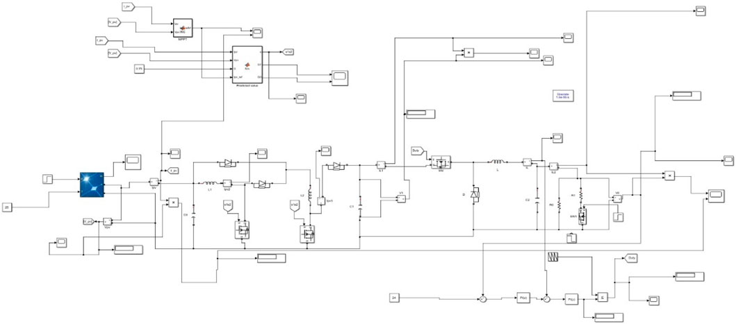
Figure 19. Simulation of voltage regulation of the proposed PV system using a DC-DC buck converter.
The analysis for this system is categorized under two scenarios, where the irradiation and load values are varied. Figure 20 shows the result for first changing the irradiation from 900 W/m2 to 1,000 W/m2 at t = 0.4 s, followed by changing the load resistance from 5 Ω to 4.17 Ω at t = 0.5 s. The changes caused by the irradiation and load resistance are reflected in the output voltage and power waveforms. From this figure, it is noted that the change in load at t = 0.5 s reflects a small dip attributable to the reference value over a short time; here, the reference value is 24 V. Next, the changes in the output power of the bus and PV system are shown in Figure 21. The nature of the output power is also influenced by the current, as seen from the output current in Figure 22.
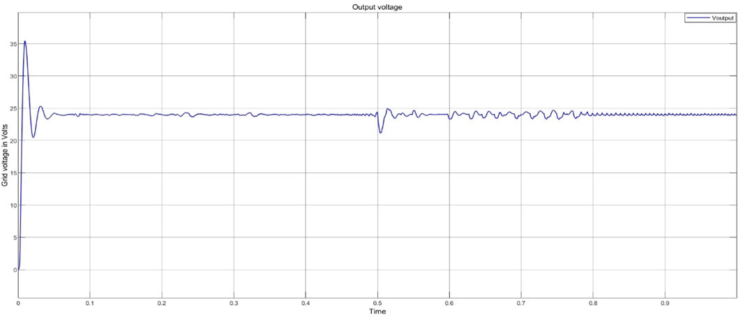
Figure 20. Voltage regulation of the PV system for varying load and irradiation conditions.
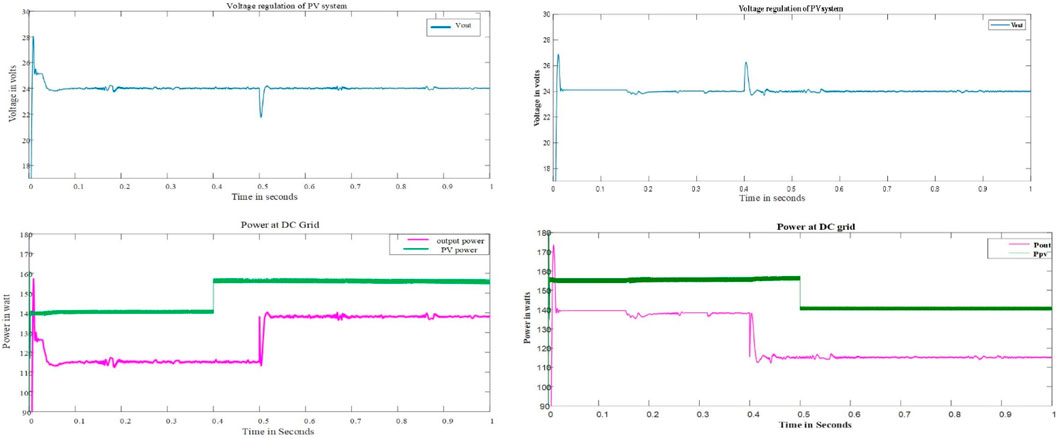
Figure 21. Output power at the bus and PV power under varying load and irradiation conditions.
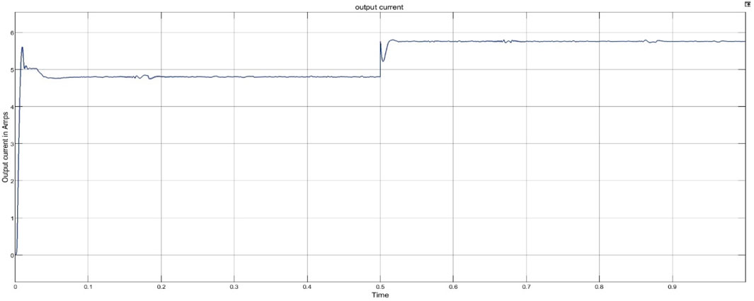
Figure 22. Output current at the under varying load and irradiation conditions.
5.4 Comparison between the proposed MPC-MPPT and IC methods
Figure 23 compares the output power and voltage values of the proposed and conventional IC methods. It is seen from the power generated at an irradiation intensity of 1,000 W/m2 that the proposed technique has better performance than the IC approach.
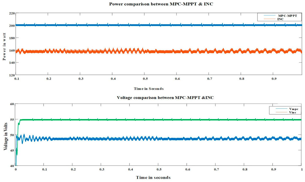
Figure 23. Comparison between the proposed MPC-based MPPT and incremental conductance methods.
6 Conclusion
Solar energy is one of the most prominent energy sources, and its efficient utilization has become a matter of important concern in recent times. In this work, we propose a new MPC-based MPPT technique with a high-gain DC-DC converter. We show through the results that MPPT with the MPC-based approach provides better transient responses. Similar advantages and results were observed even when different environmental conditions were considered. The selection of a control strategy for MPPT depends on its ease of application, simplicity, and cost reduction. The proposed MPPT achieves similar results as those in literature with only two sensors, namely one voltage and one current sensors. The MPC-MPPT has two operating modes based on fixed and variable step changes. The fixed-step operation was analyzed for different step changes between 0.02 and 0.05, and the results show significant differences and better results at a step value of 0.05. The variable-step operation was also evaluated and shown to be advantageous over fixed-step operation as the step size can be changed as per requirement. The second part of this work was concerned with voltage regulation of the PV system to allow injection of the excess available power into a grid or any to other application. Despite assessing the system for variations in the irradiation (900 W/m2 to 1,000 W/m2) and load (5–4.17 Ω) conditions, it was shown that the system managed to maintain the reference output voltage (24 V). The PV power increased as the irradiation increased, while the output power only increased when the load was reduced. As a result, the overall system performance was efficient, which is expected to improve the power quality supplied to DC microgrids. Our future work is aimed at validating the proposed concepts through experiments.
Data availability statement
The raw data supporting the conclusions of this article will be made available by the authors, without undue reservation.
Author contributions
KB: conceptualization, data curation, formal analysis, investigation, methodology, software, validation, and writing–original draft. UM: conceptualization, data curation, project administration, resources, supervision, validation, visualization, and writing–review and editing. FA: funding acquisition, project administration, resources, supervision, validation, and writing–review and editing.
Funding
The author(s) declare that no financial support was received for the research, authorship, and/or publication of this article.
Acknowledgments
This work was supported by the Researchers Supporting Project (no. RSPD2024R646) of King Saud University, Riyadh, Saudi Arabia.
Conflict of interest
The authors declare that the research was conducted in the absence of any commercial or financial relationships that could be construed as a potential conflict of interest.
Publisher’s note
All claims expressed in this article are solely those of the authors and do not necessarily represent those of their affiliated organizations, or those of the publisher, the editors, and the reviewers. Any product that may be evaluated in this article, or claim that may be made by its manufacturer, is not guaranteed or endorsed by the publisher.
Abbreviations
PV, photovoltaic; MPPT, maximum power point tracking; P&O, perturb and observe; MPC, model predictive control; DC, direct current; VMC, voltage multiplier cell; VMR, voltage multiplier rectifier; PID, proportional integral derivative; PWM, pulse width modulation; IC, incremental conductance; MPP, maximum power point.
References
Abdel-Rahim, O., and Wang, H. (2020). A new high gain DC-DC converter with model-predictive-control based MPPT technique for photovoltaic systems. CPSS Trans. Power Electron. Appl. 5 (2), 191–200. doi:10.24295/cpsstpea.2020.00016
Abdel-Salam, M., El-Mohandes, M. T., and El-Ghazaly, M. (2020). An efficient tracking of MPP in PV systems using a newly-formulated P&O-MPPT method under varying irradiation levels. J. Electr. Eng. and Technol. 15, 501–513. doi:10.1007/s42835-019-00283-x
Al-Wesabi, I., Fang, Z., Wei, Z., and Dong, H. (2022). Direct sliding mode control for dynamic instabilities in DC-link voltage of standalone photovoltaic systems with a small capacitor. Electronics 11 (1), 133. doi:10.3390/electronics11010133
Basha, C. H., and Rani, C. (2020). Different conventional and soft computing MPPT techniques for solar PV systems with high step-up boost converters: a comprehensive analysis. Energies 13 (2), 371. doi:10.3390/en13020371
Bollipo, R. B., Mikkili, S., and Bonthagorla, P. K. (2020a). Critical review on PV MPPT techniques: classical, intelligent and optimisation. IET Renew. Power Gener. 14 (9), 1433–1452. doi:10.1049/iet-rpg.2019.1163
Bollipo, R. B., Mikkili, S., and Bonthagorla, P. K. (2020b). Hybrid, optimal, intelligent and classical PV MPPT techniques: a review. CSEE J. Power Energy Syst. 7 (1), 9–33. doi:10.17775/CSEEJPES.2019.02720
Fang, X., Ding, X., Zhong, S., and Tian, Y. (2019). Improved quasi-Y-source DC-DC converter for renewable energy. CPSS Trans. Power Electron. Appl. 4 (2), 163–170. doi:10.24295/cpsstpea.2019.00016
Ferreira, S. C., Gonzatti, R. B., Pereira, R. R., da Silva, C. H., da Silva, L. E. B., and Lambert-Torres, G. (2018). Finite control set model predictive control for dynamic reactive power compensation with hybrid active power filters. IEEE Trans. Industrial Electron. 65 (3), 2608–2617. doi:10.1109/tie.2017.2740819
Forouzesh, M., Siwakoti, Y. P., Gorji, S. A., Blaabjerg, F., and Lehman, B. (2017). Step-up DC-DC converters: a comprehensive review of voltage-boosting techniques, topologies, and applications. IEEE Trans. Power Electron. 32 (12), 9143–9178. doi:10.1109/tpel.2017.2652318
Ibrahim, A. W., Zhijian, F., Farh, H. M. H., Dagal, I., Al-Shamma'a, A. A., Al-Shaalan, A. M., et al. (2024). Hybrid SSA-PSO based intelligent direct sliding-mode control for extracting maximum photovoltaic output power and regulating the DC-bus voltage. Int. J. hydrogen energy 51, 348–370. doi:10.1016/j.ijhydene.2023.10.034
Jiang, Y., Abu Qahouq, J. A., and Haskew, T. A. (2013). Adaptive step size with adaptive-perturbation-frequency digital MPPT controller for a single-sensor photovoltaic solar system. IEEE Trans. Power Electron. 28 (7), 3195–3205. doi:10.1109/tpel.2012.2220158
Kart, S., Demir, F., Kocaarslan, İ., and Genc, N. (2024). Increasing PEM fuel cell performance via fuzzy-logic controlled cascaded DC-DC boost converter. Int. J. Hydrogen Energy 54, 84–95. doi:10.1016/j.ijhydene.2023.05.130
Kumar, K., Kiran, S. R., Ramji, T., Saravanan, S., Pandiyan, P., and Prabaharan, N. (2020). Performance evaluation of Photo voltaic system with quadratic boost converter employing with MPPT control algorithms. Int. J. Renew. Energy Research-IJRER 10 (1).
Kumar, M., Panda, K. P., Rosas-Caro, J. C., Valderrabano-Gonzalez, A., and Panda, G. (2023). Comprehensive review of conventional and emerging maximum power point tracking algorithms for uniformly and partially shaded solar photovoltaic systems. Ieee Access 11, 31778–31812. doi:10.1109/access.2023.3262502
Liu, X., Zhang, X., Hu, X., Chen, H., Chen, L., and Zhang, Y. (2019). Interleaved high step-up converter with coupled inductor and voltage multiplier for renewable energy system. CPSS Trans. Power Electron. Appl. 4 (4), 299–309. doi:10.24295/cpsstpea.2019.00028
Lupangu, C., and Bansal, R. C. (2017). A review of technical issues on the development of solar photovoltaic systems. Renew. Sustain. Energy Rev. 73, 950–965. doi:10.1016/j.rser.2017.02.003
Ma, M., Liu, X., and Lee, K. Y. (2020). Maximum power point tracking and voltage regulation of two-stage grid-tied PV system based on model predictive control. Energies 13 (6), 1304. doi:10.3390/en13061304
Mei, Q., Shan, M., Liu, L., and Guerrero, J. M. (2011). A novel improved variable step-size incremental-resistance MPPT method for P.V. systems. IEEE Trans. Industrial Electron. 58 (6), 2427–2434. doi:10.1109/tie.2010.2064275
Metry, M., and Balog, R. S. (2020). An adaptive model predictive controller for current sensorless MPPT in PV systems. IEEE Open J. Power Electron. 1, 445–455. doi:10.1109/ojpel.2020.3026775
Rafikiran, S., and Alsaif, F. (2024). Design of adaptive hybrid MPPT controllers with universal input voltage DC–DC converter for RES’s. Sci. Rep. 14 (1), 11379. doi:10.1038/s41598-024-62208-7
Ram, P., Babu, T. S., and Rajasekar, N. (2017). A comprehensive review on solar P.V. maximum power point tracking techniques. Renew. and Sustain. Energy Rev. 67, 826–847. doi:10.1016/j.rser.2016.09.076
Sharma, R., and Suhag, S. (2020). Feedback linearization based control for weak grid connected PV system under normal and abnormal conditions. Front. Energy 14, 400–409. doi:10.1007/s11708-017-0459-5
Sunddararaj, S. P., Rangarajan, S. S., Subramaniam, U., Collins, E. R., and Senjyu, T. (2021). “Performance of P/PI/PID based controller in DC-DC converter for PV applications and smart grid technology,” in 2021 7th international conference on electrical energy systems (ICEES), 11-13 February 2021, Chennai, India, (IEEE), 171–176.
Suthar, M., Bhasker Manthati, U., Arunkumar, C. R., Punna, S., Alsaif, F., and Zaitsev, I. (2024). Enhancing electric vehicle performance with a hybrid PI-sliding mode controller for battery supercapacitor integration. Int. J. Energy Res. 2024, 1–13. doi:10.1155/2024/1105301
Tarzamni, H., Gohari, H. S., Sabahi, M., and Kyyrä, J. (2023). Nonisolated high step-up dc–dc converters: comparative review and metrics applicability. IEEE Trans. Power Electron. 39 (1), 582–625. doi:10.1109/tpel.2023.3264172
Xie, M., Gulzar, M. M., Tehreem, H., Javed, M. Y., and Rizvi, S. T. H. (2020). Automatic voltage regulation of grid connected photovoltaic system using Lyapunov based sliding mode controller: a finite—time approach. Int. J. Control, Automation Syst. 18 (6), 1550–1560. doi:10.1007/s12555-019-0563-x
Xu, Q., Vafamand, N., Chen, L., Dragičević, T., Xie, L., and Blaabjerg, F. (2020). Review on advanced control technologies for bidirectional DC/DC converters in DC microgrids. IEEE J. Emerg. Sel. Top. Power Electron. 9 (2), 1205–1221. doi:10.1109/jestpe.2020.2978064
Keywords: model predictive control, photovoltaic, maximum power point tracking, perturb and observe method, incremental conductance method, high-gain DC-DC converter, voltage regulation
Citation: Bhagwan KA, Manthati UB and Alsaif F (2024) A model predictive control based MPPT technique for novel DC-DC converter and voltage regulation in DC microgrid. Front. Energy Res. 12:1471499. doi: 10.3389/fenrg.2024.1471499
Received: 27 July 2024; Accepted: 12 August 2024;
Published: 29 August 2024.
Edited by:
Praveen Kumar Balachandran, Universiti Kebangsaan Malaysia, MalaysiaReviewed by:
Ahmed Allehyani, Jeddah University, Saudi ArabiaMusfer Alraddadi, Yanbu Industrial College, Saudi Arabia
Copyright © 2024 Bhagwan, Manthati and Alsaif. This is an open-access article distributed under the terms of the Creative Commons Attribution License (CC BY). The use, distribution or reproduction in other forums is permitted, provided the original author(s) and the copyright owner(s) are credited and that the original publication in this journal is cited, in accordance with accepted academic practice. No use, distribution or reproduction is permitted which does not comply with these terms.
*Correspondence: Faisal Alsaif, ZmFhbHNhaWZAa3N1LmVkdS5zYQ==