- School of Electrical Engineering, Vellore Institute of Technology, Vellore, Tamil Nadu, India
The increasing demand for renewable energy sources necessitates the development of sophisticated control systems that can seamlessly integrate and manage multiple power sources. This research introduces an advanced intelligent adaptive neuro fuzzy-based control (IANFC) for multiport DC-AC converters with differential power processing (DPP) converters, tailored for customized hybrid renewable power generation systems (HRPGS). The system aims to optimize HRPGS performance and efficiency through neuro-fuzzy control techniques. When integrating different DC power sources, such solar panels and wind turbines, into AC loads or the grid, multiport DC-AC converters are essential. These converters reduce the amount of power conversion steps, which improves the system’s overall efficiency and scalability. Complementary DPP converters process only the differential power, thereby significantly reducing total power consumption and conversion losses. The IANFC framework combines fuzzy logic reasoning, based on rules, with neural network adaptive learning capabilities. This hybrid control method effectively manages the nonlinear and dynamic behavior of HRPGS, ensuring reliable performance under varying load demands and environmental conditions. The controller dynamically adjusts the converter’s operating point to ensure optimal power flow and system stability. Simulation findings using MATLAB/Simulink verify the efficacy of the suggested IANFC system. Under various operational situations, key performance measures like response time, stability, and system efficiency are examined. As evidenced by the data, system performance has significantly improved as compared to traditional control techniques. The proposed system demonstrates an efficiency of 99.45% and achieves stability in just 0.02 s. Compared to conventional algorithms, this approach shows superior performance across multiple metrics.
1 Introduction
The growing need for renewable energy means that creative control systems are needed to efficiently integrate and manage multiple power sources. Hybrid renewable energy producing systems (HRPGS) combine many renewable energy sources, including solar and wind power, to deliver a consistent and reliable power supply. A multiport DC-AC converter is a crucial part of these systems, since it facilitates the integration of various DC inputs into a single AC output. By processing only differential power, DPP (Differential Power Processing) converters further improve efficiency and lower losses. This research suggests using intelligent adaptive neuro fuzzy control (IANFC) to maximize HRPGS performance. In order to manage the nonlinear and dynamic behavior of HRPGS, this advanced control technique makes use of rule-based fuzzy logic reasoning and neural networks’ adaptive learning capabilities. Real-time dynamic adjustment of the converter operating point is made by the IANFC system to guarantee stable and effective energy management. The suggested system performs well in terms of efficiency, stability, and response time under a range of operating situations, according to thorough simulations conducted in MATLAB/Simulink. Future developments and commercialization are made possible by the integration of IANFC with multiport DC-AC and DPP converters, which offers a strong, effective, and flexible response to the problems that contemporary renewable energy systems face.
The current electrical transmission system cannot handle the exponential growth in demand for electricity. In order to satisfy consumer demand, distributed generation must be generated locally or funds must be allocated to expand the transmission infrastructure’s capacity. Comparing renewable energy sources like solar and wind requires the usage of both large and local networks. If the effect on system voltage, frequency stability, and interference levels is not taken into consideration, the inclusion of an unconventional energy source may result in interruptions, power outages, and vulnerabilities in the network. Furthermore, during consumption, the voltage and frequency will fluctuate if the installed capacity of non-conventional energy is equal to that of conventional energy. Since unconventional energy is irregular and unpredictable, it is challenging to predict how much electricity will be produced.
Numerous experts have observed the possible effects of increasing small-scale power production technologies’ integration and deployment on grid efficiency. It is imperative to address the significant issue of microgrid electricity output’s unpredictability. The variability of the cargo supply can be mitigated in a number of methods, such as demand-side management, generation dispatch, and storage device integration. Engineers are never able to come up with a good solution when they have too many possibilities.
The global fight against global warming requires a significant increase in renewable energy in the electricity industry. This requires considering power quality, grid stability, and reliability. Utilizing renewable energy near the load centre can optimize operational efficiency and reduce transmission losses. Microgrids, small-scale grids, concentrate power generation resources in a small geographic region, using natural renewable energy as the primary energy source. Renewable energy systems’ intermittency needs to be managed in order to meet load requirements as shown in Supplementary Figure S1.
One of the key advantages of hybrid solar power systems over traditional solar power systems is continuous power delivery. The battery of a hybrid solar system can hold energy to deliver power continually. Batteries serve as inverters during blackouts, providing backup power for your home and important appliances. The battery provides backup power to keep the device operational during a blackout or power loss. This system’s long-term cost effectiveness is another benefit. The consumer ultimately saves money even though the initial cost of these systems may be higher because they require less maintenance and do not require the purchase of fuel, unlike generators. Conventional generators have a limited initial energy output as shown in Supplementary Figure S2. On the other hand, hybrid solar energy systems disperse energy at night after storing it during the day. Technology can be utilized to automatically modify a hybrid solar system’s energy intake according to the power requirements of particular appliances, including air conditioners and fans.
Multiport converters (MPCs) are a way to reduce the number of converters required in these power systems by combining many converters into a single unit. MPCs can be classified as partially insulated, insulated, or non-insulated. You can expand the number of input/output ports by using inverter bridges and windings. Power and storage components in DC microgrids are usually connected by means of separate power electronic converters (DCMGs), which can be single- or multi-stage. However, voltage fluctuations, complicated protection requirements, high system costs owing to switch activation, and decreased efficiency due to more conversion steps are the main drawbacks of these configurations (particularly for intermediate energy and energy storage devices). Multiport converter (MPC) technology is a great choice for different voltage levels since it enables bidirectional power flow between different energy storage devices (batteries, supercapacitors, etc.) and power sources (solar energy, fuel cells, etc.). Conventional DCMG architectures with their complex communication specifications and superfluous conversion steps are eliminated. The use of multiport converters (MPCs) is becoming increasingly popular in non-logic power supplies, satellite communications, microgrids, and hybrid vehicles. Transformer-isolated MPC topologies are particularly advantageous for applications requiring high voltage conversion rates, as they allow for the achievement of the desired voltage gain by adjusting the transformer’s turns ratio.
The energy demand boom is primarily driven by industrialization and population growth, along with a shortage of traditional energy sources like coal, oil, and natural gas. Self-renewable energy sources like geothermal, biomass, solar, wind, and water are crucial for environmental protection and energy security, with solar and wind being the most promising (Arani et al., 2019).
In renewable energy systems, static power converters are utilized to enhance power tracking, adjust the power supply according to load demands, and improve both static and dynamic characteristics (Mihai, 2015; Gunasekaran and Chakraborty, 2023), as noted by Mihai. Power electronic converters, either single- or multi-stage, are needed based on the output characteristics when connecting batteries and hybrid renewable energy sources to the load or grid. It is perfect to link several renewable energy sources to a load using multiport converters, which are more economical and efficient than standard converters, as shown in (Dobbs and Chapman, 2003; Jiang and Fahimi, 2011; Wu et al., 2015; Madhana and Geetha, 2022; Alargt et al., 2019a; Shanmugam and Sharmila, 2022; Benavides and Chapman, 2005). In addition to comparing the benefits and drawbacks of different multiport converter topologies, A.K. Bhattacharjee and associates (Bhattacharjee et al., 2018) give an overview of multiport converters used for combining solar energy generation with energy storage systems.
Multiport converter topologies fall into three categories: partially isolated, non-isolated, and isolated. DC link or electrical coupling is used in non-isolated arrangements, and transformers are used in fully and partially isolated topologies to connect various sources or loads via magnetic coupling (Madhana and Mani, 2022). The high power density and compact design are the result of a non-isolated topology, in which ports are not split but are instead directly connected to one another. You may find a report in (Tao et al., 2008; Krishnaswami and Mohan, 2009; Ajami and Shayan, 2015; Tao et al., 2005; Zeng et al., 2013; Zeng et al., 2014; Wu et al., 2014; Savitha and Kanakasabapathy, 2016) on discrete MICs with buck-boost topology. This design is more expensive since it requires multi-winding magnetically coupled transformers and larger energy storage coils. This makes it possible for the design to include elements like turns ratio and leakage inductance that are pertinent to transformers. Consequently, it is possible to achieve great efficiency under various operating conditions.
A new soft-switching non-isolated high-boost multiport DC-DC converter that can simultaneously charge and output ESS was proposed in Rasoul Faraji’s research (Matsuo et al., 2004). It considers several aspects, including minimal converter component count, independence of every power flow line, strong boost voltage gain, and smooth switching conditions. Numerous suggested topologies for more effective voltage rise have been published in scholarly journals. One notable achievement highlighted by the authors of (Wu et al., 2011; Iannone et al., 2005) involves the integration of fuzzy logic control into dual-input DC-DC converters. This fuzzy logic control approach aims to enhance the parameters of the PID controller and modify the duty cycle of the dual-input DC-DC converter by introducing an additional nonlinear characteristic source. A modular integrated converter with DPP capabilities that was built on cascading quasi-Z source inverters was introduced in (Chakraborty et al., 2015). (Faraji and Farzanehfard, 2020) published a distributed control technique based on DPP for tracking a solar cell system’s submodule maximum power point. It is common to connect DPP designs in parallel or series. The current differential between PV cells at the module, sub-module, or cell level is mainly provided by DPP converters. Thus, features of DPP designs include module or device level, bidirectional or unidirectional, isolated or non-isolated, shared between modules or between strings. A study that using a built pulsed current source cell in (Alargt et al., 2019b) synthesized a cascade structure from two input interleaved boost converters. In (Zhang et al., 2016; Alargt et al., 2019a; Chu et al., 2019; Uno and Shinohara, 2019; R and Mani, 2023; Chu et al., 2017), developed a MPC with centralized controller using various algorithm has been discussed.
This design, which comprises of a multiport DC-AC converter (MPC) and a DC-DC converter (DPPC), is recommended to be integrated with a solar PV system that is connected to a battery energy storage system (ESS). Only a tiny portion of the power, referred to as the differential power, needs to be controlled by the DPPC; the MPC efficiently controls the remainder of the active power distribution between the PV, battery, and AC grid. This suggested strategy offers better efficacy and affordability. While prior DPP techniques primarily addressed the DC-DC stage of PV systems, our research focuses on the DC-DC and DC-AC phases of the battery ESS-integrated PV system.
An altered SVPWM approach is used in the construction of the MPC to compensate variations in PV and battery voltages. Battery-ESS integrated solar cell systems are studied, and multi-port and partial current conversion techniques are used, drawing on the literature review. The major work is focused on creating highly integrated, economical, and efficient designs by utilizing latest technical developments.
Wang et al. (2021) introduced a differential power processing (DPPC) and multi-port DC-AC converter (MPC) to integrate battery ESS and solar PV systems. The MPC regulates active power flow, while DPPC handles the differential power component. The architecture offers high integration, efficiency, and cost-effectiveness.
Elkeiy et al. (2023) developed a multi-port DC-DC converter for EV rapid charging stations, improving efficiency and reducing costs. The architecture consists of two current flow paths: outer loop and inner loop, with a primary DPPC controlling the loop’s current and an auxiliary DC-DC converter managing fractional power. This configuration offers fault tolerance and cost-effectiveness.
Perera et al. (2021) propose a bidirectional multiport converter with twin inverters, allowing a single power unit to power DC/AC converters using solid-state and magnetic drives. This configuration offers more power limit and efficiency than traditional methods due to inverter multitasking and single-stage DC/DC and DC/AC power transmission techniques. Independent inverter control ensures uninterrupted power transfer even in case of failure.
Madana et al. developed an energy-efficient multiport converter using predictive energy correction algorithms. The converter maintains high power, transmission efficiency, and reliability while enhancing energy extraction from multiple ports. The dynamic duty cycle controls gate voltages, reducing fluctuations and improving system dependability. The converter’s performance was tested using MATLAB/SIMULINK, outperforming conventional PID controllers by 6.88%.
The major contribution of this paper in the differential power processing of MPC DC-AC converter is to manage power processing between various ports of MPC and grid. Additionally, the paper introduces the IANFC scheme for effectively controlling the nonlinear and dynamic behavior of MPC.
The Crayfish Optimization Algorithm (COA) is proposed for optimal optimization of multiple BESS sites and sizes, enhancing peak demand, power loss, and voltage deviation performance (Pompern et al., 2023). The study identifies optimal BESS locations and dimensions for distribution networks, aiming to reduce power loss and voltage variation expenses, comparing particle swarm optimization and genetic algorithms (Boonluk et al., 2020). BESS capacity, PV and EV integration improve distribution system efficiency, reduce expenses, and enhance voltage profile. Metaheuristic methods optimize setup, maintenance, transmission losses, and voltage profile (Wichitkrailat et al., 2024).
This is how the rest of the article is organized. In Section 2, the basic idea of the MPC with DPPC is provided, followed by the related topologies. A detailed discussion of the various control and modulation approaches is provided in Section 3. After a quantitative analysis of the MPC’s active power regulation, Section 4 presents the results of the suggested system’s simulation. Ultimately, significant conclusions are established in Section 5.
2 Multiport converter
In the context of this study, the Multiport Converter (MPC) is a crucial part that makes it easier for HRPGS to manage and integrate different renewable energy sources efficiently. An energy storage device, wind turbine, solar panel, or other DC source can be interfaced with an AC demand or grid through the use of an MPC. This allows for smooth power distribution while reducing the energy losses that occur during conversion operations. Because of its flexible, scalable, and efficient design, it can accommodate a wide range of energy sources and load needs. The MPC ensures optimal resource use by providing adaptability to changing system requirements through its modular architecture. Furthermore, the application of complex techniques like Differential Power Processing (DPP), which further improve system stability and efficiency, is made possible by the MPC’s sophisticated control capabilities. The performance of the MPC is examined in detail throughout this work, with the goal of enhancing its functioning under various operating conditions and load profiles using simulations and experimental validations. The MPC, a key component of HRPGS, not only makes it easier to integrate renewable energy sources smoothly, but it also makes a major contribution to the advancement of sustainable power generating techniques.
2.1 Configuration of the MPC with DPPC for different modes of operation
It has been researched that DPPC systems can function quite well under unfavorable and partial shadowing scenarios. While they are connected to each PV panel in a similar manner as Full Power Processing Converters (FPPCs), DPP converters are built differently. The DPP converters transfer very little power to keep the MPP operating in the case of a PV panel mismatch. Stated differently, DPP systems require less electricity processing than FPP systems. The main current flow of the DPP and FPP systems is depicted in Supplementary Figure S3. It is evident that the FPPC consumes all of the PV power after receiving the principal power in the FPPC system. Only a fraction of the electricity from the PV panels is processed by the DPP converters in the DPPC system. This implies that converter loss and component costs can be reduced because the DPP converter’s power rating is lower than the FPP converter’s. Since the DPP converters might not always receive full power, reducing wear on them also improves reliability.
Voltage equalizers and DPPC are being actively pursued as effective partial shading solutions. Different classes of DPP converters are categorized based on potential power redistribution scenarios. DPP converters can be made using single-input, multiple-output, bidirectional, and isolated converters. This is accomplished by using a Differential Electricity Processing (DPPC) converter, which transfers electricity to the battery by processing only a fraction of the power flowing from a generator (in this case, a PV string). In comparison, Supplementary Figure S4 illustrates a more conventional complete power processing method in which the converter processes all of the power a DPP converter operating in boost and buck modes is shown in Supplementary Figure S4. This DPP converter’s operating mode is determined by the relative voltages, which are boost mode for VPV > VBATT and buck mode for VPV < VBATT.
3 Control of MPC and PWM method
In the field of MPC control, pulse width modulation (PWM) techniques are essential for managing power flow between the converter’s ports and the load or grid. By altering the pulse widths of the signals, PWM approaches regulate the average voltage or current applied to the converter’s output. This provides accurate control over power transfer and improves system stability and efficiency. PWM control of MPC requires a number of important factors. First, the system topology, switching frequency, and required performance criteria all play a role in choosing the best PWM approach, be it space vector PWM or sinusoidal PWM. Space vector PWM, which offers improved efficiency and harmonic performance, and sinusoidal PWM, which is well-known for its simplicity and compatibility with grid-tied applications, are popular options. Furthermore, key factors in PWM control that affect the waveform and harmonic content of the converter’s output voltage are modulation index, duty cycle, and switching frequency. The MPC can minimize distortion and losses while meeting voltage and current requirements by precisely adjusting these parameters.
Along with PWM approaches, the control algorithm selection also has a big impact on MPC performance. Examples of sophisticated control systems that provide precise regulation of converter operation, enhancing dynamic response and stability under a variety of operating conditions, include hysteresis control, model predictive control and proportional-integral-derivative (PID) control. By combining advanced control algorithms and PWM approaches, MPCs in HRPGS are essentially given the ability to efficiently manage power flow between renewable energy sources and the grid. By combining robust control algorithms with PWM approaches, MPCs help to construct sustainable energy systems that facilitate dependable and efficient power conversion, contributing to the creation of a more ecologically friendly future.
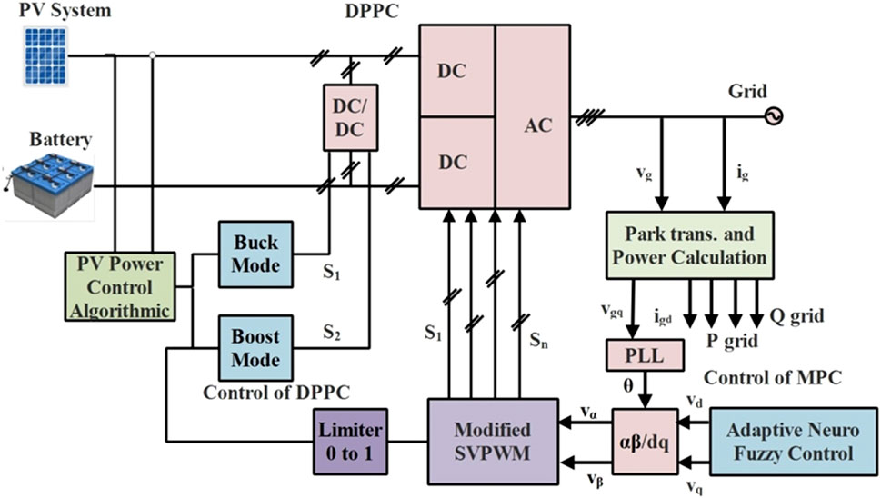
A Dual-Port Power Converter is used in Figure 1 to integrate a photovoltaic (PV) system with a battery storage unit and a power grid through a complex control architecture. A control algorithm is used to maximize the PV system’s output of electricity. The battery stores extra energy, which is then released when needed. Energy transfer between the PV system, battery, and grid is managed by the DPPC, which has stages for DC/DC and DC/AC conversion. It can function in either the Boost or Buck modes, depending on the situation. A limiter controls control signals, and modified space vector pulse width modulation, or SVPWM, enables effective inverter management.
The flexibility and resilience of an Adaptive Neuro-Fuzzy Control system are enhanced. Park transformation is utilized for power computation, phase-locked loops (PLLs) are used for grid synchronization, and dq coordinate transformation is employed for efficient inverter control. This integrated system ensures efficient power conversion, storage, and distribution while maintaining peak performance and stability. The output of the PV power control loop is indicated by the parameter k, and the ratio of positive to negative tiny vectors is controlled by the control parameter kc (0 ≤ kc < 1). The driving signal for switch S1 is obtained by comparing k to a triangle carrier ranging from −1 to 0, and the driving signal for switch S2 is obtained by comparing k to a triangular carrier ranging from 1 to 2. Figure 1 demonstrates how the system exhibits varied behavior based on different values of k.
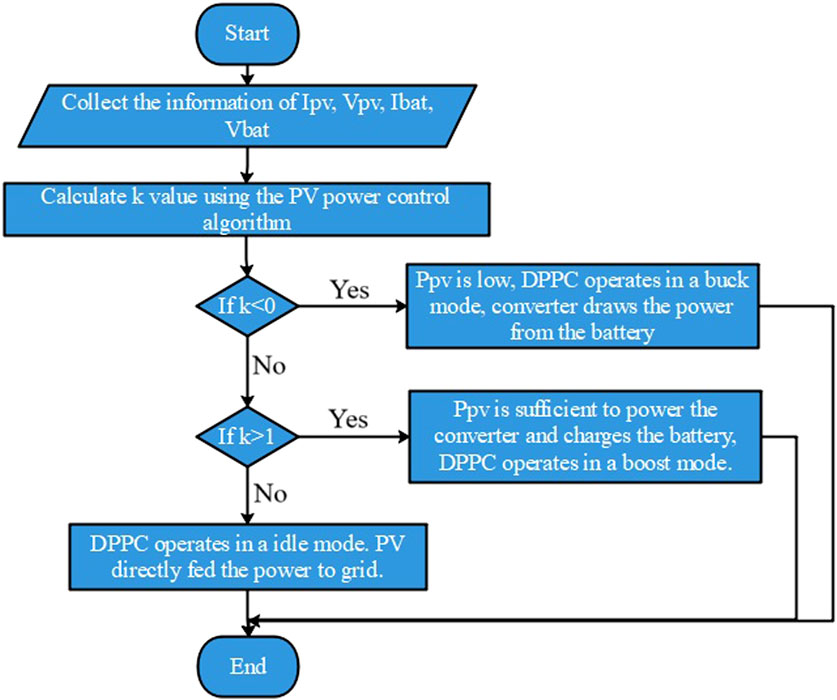
Case 1. where the k lies between 0 and 1 where k = kc where switches S1 and S2 are both turned off and DPPC is in non-operative condition where MPC regulates the SES and grid.
Case 2. where the k < 0 switch is When the solar energy power supply is low, S1 turns on and the DPPC operates in a buck fashion. The battery empties and powers the converter.
Case 3. where the DPPC operates in boost mode, charging the battery with solar energy and powering the converter, and the k > 1 switch S2 begins to turn on.
Figure 2 shows the flowchart of power flow management of HRPGS using differential power processing converter for the above-mentioned cases.
3.1 Modified space vector modulation PWM (MSVPWM)
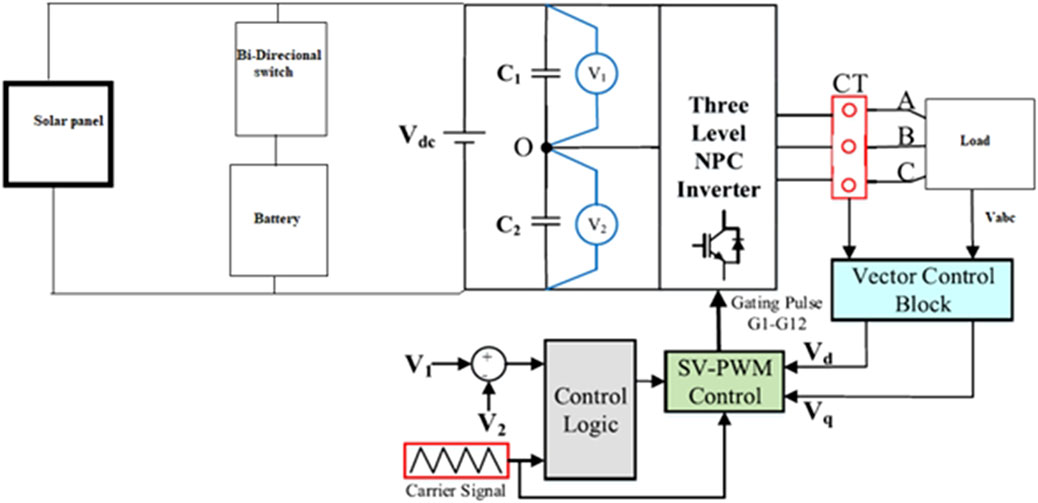
In the traditional SVPWM system, the number of switching sequences vary across subregions, changing the switching frequency and ultimately increasing the switching loss. Due to these drawbacks, improved space vector modulation PWM techniques have been published in a number of scholarly journals in an effort to reduce losses and maximize the DC link capacity. In this work, the voltages of the DC link capacitors are compared and incorporated into the control logic alongside a carrier signal. This combination of inputs is utilized to determine the necessary switching sequence for the Space Vector Modulation (SVM) approach.
The control system shown in Figure 3 combines a three-level Neutral Point Clamped (NPC) inverter with a load consisting of a solar panel and battery storage. The DC power produced by the solar panel is controlled by a bidirectional switch that is connected to the battery, allowing for flexible energy supply and energy storage. The DC power (V_dc) is received by the NPC inverter, which uses switches (V1, V2) and capacitors (C1, C2) to generate a three-level voltage output. The inverter converts DC power into AC power to service a load connected at points A, B, and C. Current transformers (CT) measure the current flowing to the load and supply the Vector Control Block with this information. This block computes the direct (V_d) and quadrature (V_q) voltage components in order to precisely control the inverter output.
The control logic receives the carrier signal (Vcarrier) and reference signals (V1, V2), and then creates the appropriate gating pulses (G1-G12) for the inverter switches. The SVPWM control optimizes the inverter switching to produce a stable AC output. This integrated system ensures the efficient conversion of solar and battery storage energy into the load, maintaining performance and stability through the application of cutting-edge control techniques.
When Vdc1 is greater than Vdc2, the switching sequence is selected to discharge Vdc1. In a similar vein, when Vdc2 surpasses Vdc1, the switching sequence is selected to permit Vdc2 to be discharged. The corresponding switching sequence is given in Supplementary Table S1. The DC link capacitance’s voltage is balanced using this arrangement. The control logic will only update the voltage difference information at the beginning of each switching cycle in order to prevent duty cycle alterations in between switching cycles. It generates PWM with a constant switching frequency and an equal switching sequence under all conditions as shown in Supplementary Figure S5. A consistent switching frequency leads to a decrease in the switching frequency.
3.2 Adaptive neuro-fuzzy inference system (ANFIS)
The ANFIS is a hybrid intelligent framework that combines the learning capabilities of neural networks with the reasoning abilities of fuzzy logic. This amalgamation effectively models complex, nonlinear systems by capitalizing on the strengths of both methodologies. The ANFIS utilizes a structured architecture that consists of a neural network training algorithm that optimizes the fuzzy if-then rules and membership functions using input-output data, and a fuzzy inference system that includes fuzzy rules. Five layers typically make up an architecture: the first layer handles input variables and their fuzzy membership functions; the second layer evaluates the strength of the rules using fuzzy logic operators; the third layer normalizes these strengths; the fourth layer establishes the rules’ consequent parameters; and the fifth layer aggregates the results to produce the final output. ANFIS modifies the parameters of the membership functions and rules during the learning process, frequently using techniques like backpropagation or hybrid learning integrating least squares and gradient descent. Improving forecast accuracy and reducing error are the main goals.
Due to its versatility in handling uncertainties, modeling nonlinear relationships, and adapting to varying conditions, ANFIS finds extensive application across various domains, including signal processing, control systems, pattern recognition, and decision-making processes. Its precision and adaptability enable the successful resolution of intricate problems in engineering, finance, and other fields. ANFIS controllers, resulting from the fusion of Fuzzy Logic Control (FLC) and artificial neural networks, are preferred for their capability to perform effectively across diverse scenarios and their automatic real-time parameter adjustments ensuring optimal control.
The architecture of an ANFIS is depicted in Supplementary Figure S6, illustrating the fusion of fuzzy logic reasoning and neural network learning. The process begins with the Fuzzification block, where an error signal is transformed into fuzzy inputs using predefined membership functions. The Decision Making block then analyzes these fuzzy inputs using a Knowledge Base containing membership functions and fuzzy rules. The system’s adaptability to changing input conditions is enhanced by the NN-based Rule Update block, which utilizes neural network training techniques to continually refine these rules and membership functions. This neural network approach maintains a knowledge base that enhances fuzzy inference, leading to more precise decision-making. Despite the decision-making process, the outcome remains uncertain. The Defuzzification block converts this fuzzy output into a crisp value, which is then utilized in real-world applications by control systems such as digital-to-analog converters (DAC). This transformation is crucial for the fuzzy logic system to produce actionable insights.
For a variety of intricate, nonlinear applications, our ANFIS architecture offers resilient and flexible control overall. By merging the advantages of neural networks and fuzzy systems, it achieves this. NN receives different inputs according to inputs; NN has a standard output, thus training NN depends on both input and output; the FL receives the NN output and uses MATLAB to create the IF THEN rules and membership functions.
FL and ANN have emerged as prominent areas of study for addressing control problems. This trend can be attributed to the limitations of classical control theory, which often necessitates statistical controller designs. Control performance is frequently hindered by the imprecision in the mathematical modeling of the plant, particularly in complex and nonlinear control scenarios. The advancement of neural controllers based on multi-layered neural networks (NNs) and fuzzy logic controllers (FLCs) holds promise for enhancing control efficacy and expanding knowledge in this field. The integration of FL and NN has led to the development of FNN, commonly referred to as ANFIS. Unlike a FL network, which typically has multiple inputs and a single output, a neural network features multiple inputs and multiple outputs. The fusion of these two approaches is proposed to yield ANFIS for nonlinear applications.
The ANFIS controllers are designed using FLC and artificial neural networks. These controllers are used because they can operate efficiently in a variety of settings and dynamically modify their settings in real time to attain the best possible control.
To model complex, nonlinear systems, the ANFIS combines the linguistic representation capacity of fuzzy logic with the adaptability of neural networks. Fuzzy sets, language variables, and inference methods like Sugeno and Mamdani are some of the tools that ANFIS, which is founded on the ideas of fuzzy logic, employs to manage uncertainty in control systems. Layers for fuzzification, rule assessment, aggregation, and defuzzification are included in ANFIS structures. These layers are complemented by neural networks, which are superior at approximating complex functions and learning from data, leading to precise outputs, as seen in Supplementary Figure S7. By fine-tuning its parameters—which are usually a combination of least squares estimation and backpropagation—the hybrid learning algorithm maximizes ANFIS performance. Real-world applications in robotics, process control, finance, and healthcare show how flexible ANFIS is when handling stochastic and nonlinear systems. Evaluation metrics like as mean squared error and correlation coefficient are used to quantify ANFIS performance, and these metrics often outperform traditional control techniques. Future research directions promise to advance ANFIS control further; these include integrating deep learning, enhancing scalability, and addressing real-time implementation challenges.
The ANFIS architecture is built upon the Sugeno Model, which consists of five layers, one output, and two inputs. Initially, the inputs undergo fuzzification, followed by de-fuzzification using an internal rule knowledge base. Each rule within the hierarchy is assigned a weight indicating its relative importance. These rules and weights can be adjusted during training to minimize errors and achieve the desired controller response. The first-order Sugeno model can be represented as follows:
u1 is the result if inputs e = A1 and Δe = B1.
u2 is the result if inputs e = A2 and Δe = B2.
Consequently, output u = w1u1 + w2u2.
The inputs that have been fuzzified are A and B, and the chosen weight is denoted by w. Supplementary Figure S8 shows the ANFIS controller’s structural layout. The following layers make up the ANFIS structure.
3.2.1 Layer 1 (input or fuzzification layer)
Membership grades are generated for the input vectors Ai = 1, 2. n for each adaptive node in this layer.
A membership function, also known as the degree of membership, is a curve ranging from 0 to 1, illustrating how input data points are transformed into membership values. The parameters within the equation aij, bij, and cij correspond to the membership functions. In this study, the crossover slope value, bij, for the Gaussian membership function is typically set to 1. The curve’s midpoint, denoted by the parameter cij, and its inflection point, represented by aij, collectively determine the curve’s width as per Equations 1–3.
3.2.2 Layer 2 (rule inference layer)
Each node’s output in this layer represents the level of activation of each rule.
3.2.3 Layer 3 (normalization layer)
The fixed node I of this layer determines the ratio of the degree of activation of the ith rule to the sum of all degrees of activation:
3.2.4 Layer 4 (consequent layer)
This layer’s adaptive node I calculates the contribution of the ith rule to the overall output using the node function below.
3.2.5 Layer 5 (output layer)
This layer’s lone fixed node computes the overall output, which is a summary of the contributions made by each rule.
Equations 3–7, which produce the result z, are simplified as in Equation 8.
4 Simulation results
The design and assessment of a simulation setup is done using MATLAB/Simulink software to confirm that the suggested configuration, control, and modulation strategies work as intended. Supplementary Tables S2, S3 present an illustration of the simulation parameters. Supplementary Table S2 contains the solar system’s parameters, while Supplementary Table S3 lists the battery system’s specifications. Using Vbat = 90 V in the experiments, the improved SVPWM scheme for the MPC is validated. The steady-state waveforms of the switching sequence are shown in Supplementary Figure S5. The reference voltage vector Vref rotates anticlockwise via S2, S3, S6, S5, and S6 when Vbat = 90 V or 100 V. It also rotates between S1 and S6 counterclockwise when Vbat = 150 V. For example, as Fiure. 4 shows, the switching sequences when Vref spins about S6 are (l,l,0)→(h,l,0)→(h,l,l)→(h,h,l)→(h,l,l)→(h,l,0)→(l,l,0). Moreover, it is observed that the halfway point of phase voltages, vxn, have been asymmetrically distributed in all other instances, with the exception of those in which the battery voltage, Vbat, is equal to half of the PV voltage, Vpv (i.e., Vbat = 100 V).
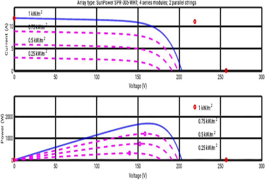
Supplementary Table S4 describes the performance of proposed IANFIS converter for different irradiation. Figure 4 depicts the IV and PV characteristics, which provide valuable insights into the behavior of electrical devices. Regarding photovoltaic systems, the I-V curve demonstrates the correlation between the current generated by a solar panel and the voltage across its terminals, thereby illustrating the panel’s response to variations in temperature and irradiance. At the short circuit current (Isc), there is no voltage across the terminals, while at the open circuit voltage (Voc), no current flows. The shape of the I-V curve can be utilized to estimate the efficiency and condition of the solar panel. Conversely, the P-V curve illustrates the relationship between the power output and the voltage across the panel, highlighting the MPP at which the solar panel operates optimally. To ensure maximum energy harvesting in a range of operating scenarios and to improve solar system efficiency and design, it is imperative to get an understanding of these qualities. A visual representation of these curves can provide valuable insights for engineers and academics in optimizing solar energy consumption and system efficiency.
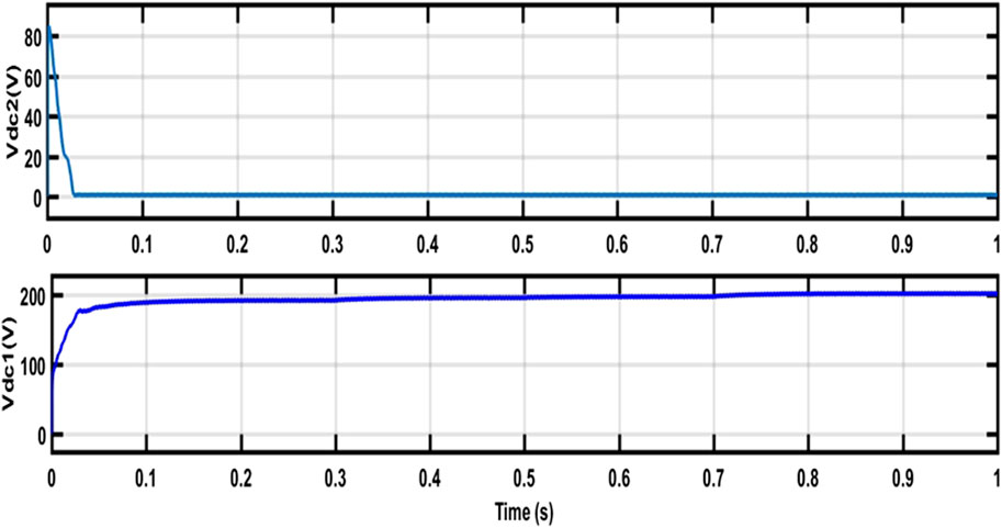
The function of capacitor voltages (Vdc1 and Vdc2) in energy storage and regulation in electrical circuits is demonstrated in Supplementary Figure S4. When shown visually, these voltages demonstrate the dynamic behavior of capacitors over time. Generally speaking, one capacitor’s voltage is indicated by Vdc1, while another capacitor’s voltage is indicated by Vdc2, usually when they are linked in series or parallel.
As the conditions of the circuit vary, capacitors charge and discharge, causing these voltage values to fluctuate. It is essential to comprehend capacitor voltage fluctuations to guarantee the stability, effectiveness, and appropriate operation of electronic systems. These voltage profiles are used by designers and engineers to maintain ideal operating conditions, avoid voltage spikes, and maximize circuit performance. Capacitor voltage visualization aids in the investigation, debugging, and optimization of electrical circuits, advancing a range of technologies from telecommunications to power electronics.
The revised SVPWM scheme for the MPC is validated through simulations using Vbat = 150 V. Figure 5 displays the switching sequence’s steady-state waveforms. When Vbat is less than the rated voltage, the reference voltage vector Vref spins through S2, S3, S6, S5, and S6 in an anticlockwise manner. When Vbat = 150 V, it also rotates counterclockwise between S1 and S6. For instance, as Vref rotates around S6, the switching sequences are as follows: (l,l,0)→(h,l,0)→(h,l,l)→(h,h,l)→(h,l,l)→(h,l,0)→(l,l,0). Moreover, it is observed that the halfway point of phase voltages, vxn, have been asymmetrically distributed in all other circumstances, except in those where the Vbat, is equal to half of the PV voltage.
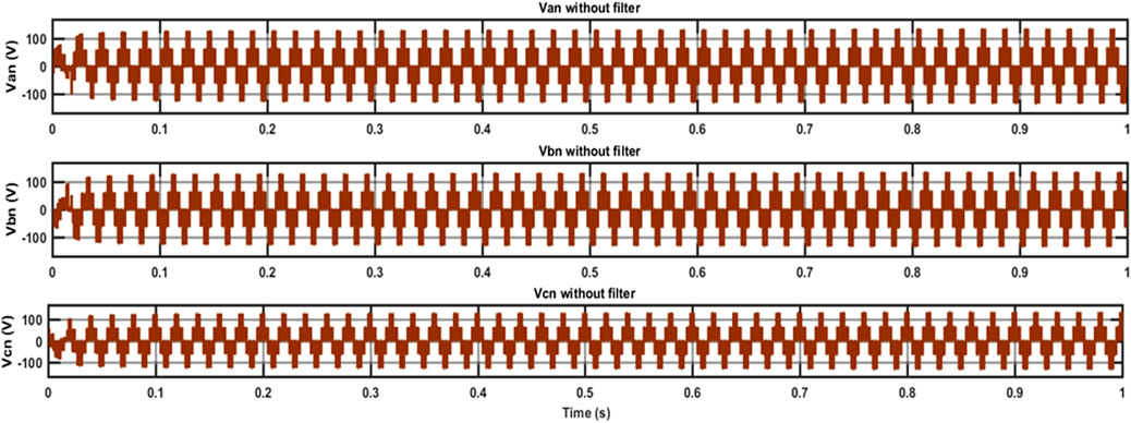
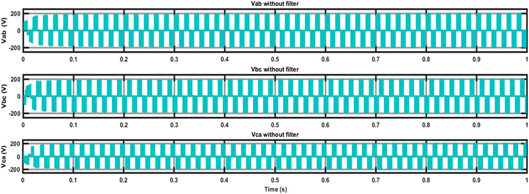
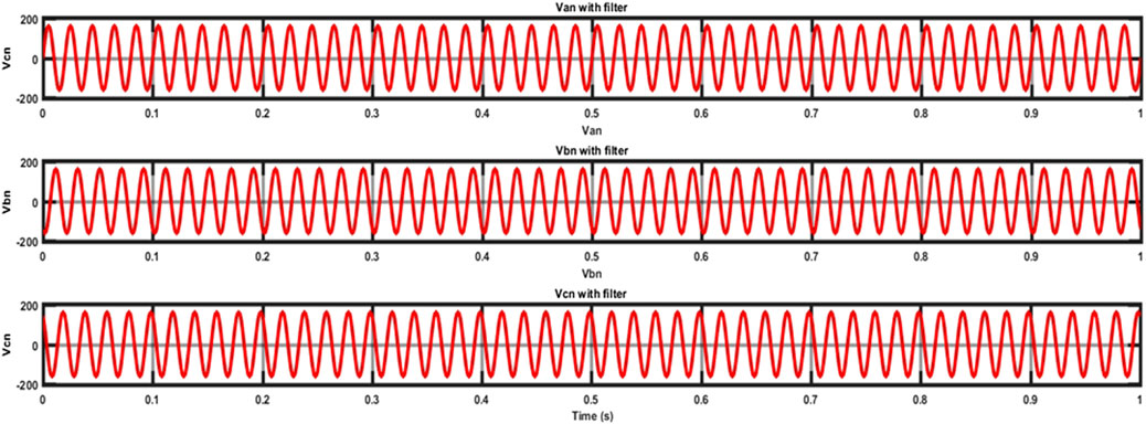
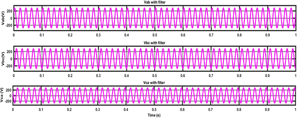
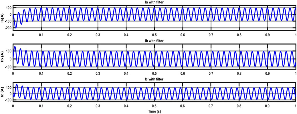
The voltage and current waveforms with and without filters are shown in graphs 6 through 10. The system’s phase and line voltages without the filter connected are displayed in Figures 6, 7, respectively. The phase and line voltage waveforms following the filter’s connection are shown in Figures 8, 9, respectively. It is evident that once the filter is connected to the circuit, the ripple content is significantly decreased. After the filter is connected, the current waveform is seen in Figure 10.
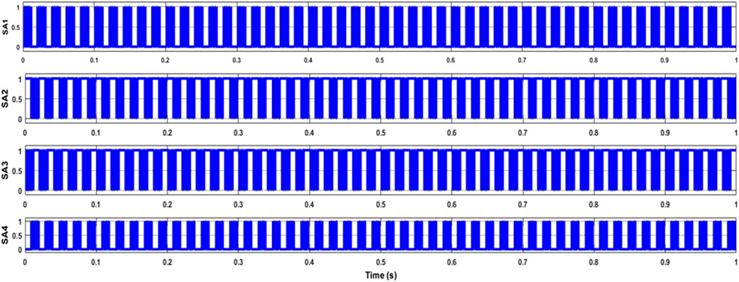
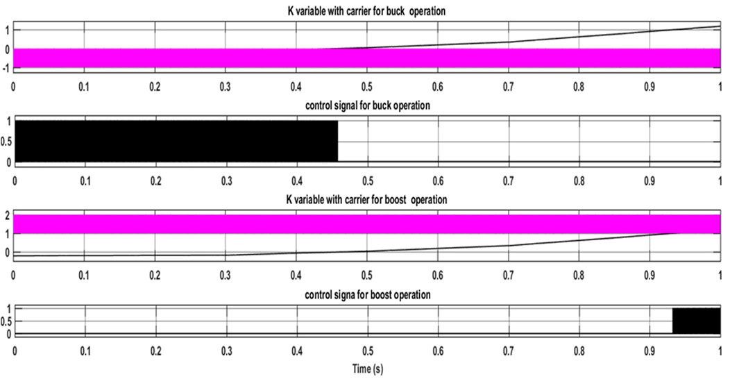
By comparing the simulation results in different scenarios, the functioning of the suggested setup is tested. Pulse signal production for various instances is shown in Figure 11. In case 1, power control is handled only by the MPC; the DPPC is not used. It drains the battery to give the remaining power needed by the grid-side power because it operates on a buck cycle. This example has a lower PV power output (Ppv) than grid-side power Battery charging or discharging is not required because photovoltaic (PV) energy supplies the ac grid with active power by matching grid-side power. In this instance, when PV power exceeds grid-side power, some of it is transferred to the ac grid and the rest is used to charge the battery. Within a certain Ppv range, it is evident that the MPC can accomplish active power regulation between the PV, battery, and ac grid.
Switch S1 on the DPPC goes on while switch S2 stays off in the following example, demonstrating how the DPPC enters the buck mode of operation when Ppv reaches its maximum value. In this case, half of the PV power that charges the battery is processed by the DPPC and the other half by the MPC. The final conceivable state is reached when Ppv reaches zero. The DPPC is using boost mode in this instance, with switch S1 off and switch S2 on. In this case, the DPPC and the MPC each supply a percentage of the battery’s active power to the ac grid. In conclusion, Figure 11 shows how the suggested configuration modifies the k value to offer appropriate performance in various scenarios depending on the fluctuating PV power.
In the following example, it is evident that the DPPC enters the buck mode of operation when Ppv reaches its maximum value, since switch S1 on the DPPC turns on while switch S2 remains off. The MPC processes a portion of the PV power used to charge the battery in this instance, while the DPPC processes the remaining portion. When Ppv is zero, that is the last case. In this instance, switch S1 is off and switch S2 is on, meaning that the DPPC is operating in boost mode. Both the DPPC and the MPC contribute a portion of the battery’s active power to the ac grid in this instance. To summarize, the recommended arrangement based on changing PV power modifies the k value to give good performance in various conditions, as shown in Figure 11.
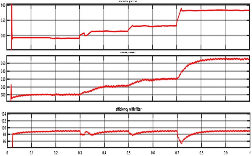
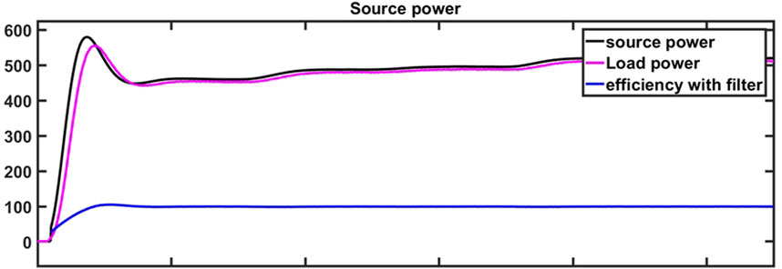
The solar input and battery system’s current, voltage, and power waveforms are shown in Supplementary Figure S9. Figure 12 shows display the fluctuation of the k value and the solar irradiance curve. Figures 13A–C, 14 shows the source power, load power, and the system’s overall efficiency in relation to each other. At the points k = 1 and k = 0, the proposed method offers a higher system efficiency. Efficiency is almost constant in the region where only MPC functions exist. Efficiency decreases as DPPC processes additional power outside of this range. Table 1 describes the comparison of different algorithms with proposed technique. The proposed IANFIS approach provided the better efficiency (99.45%) and minimum stability period (0.02s) and minimum distortion.
5 Conclusion
A reliable method for enhancing hybrid renewable power generation systems (HRPGS) is the Intelligent Adaptive Neuro-fuzzy based Control (IANFC) suggested for Multiport DC-AC converters with Differential Power Processing (DPP). This strategy provides a thorough framework for handling the challenges of integrating renewable energy sources and improving system performance by fusing cutting-edge converter technologies with sophisticated control approaches. The results of simulations and experimental validations demonstrate the efficacy of the proposed control system, underscoring its potential to significantly improve HRPGS’s efficiency, adaptability, and stability. The proposed IANFIS approach provided the better efficiency (99.45%) and minimum stability period (0.02s) and minimum distortion loss. The IANFC guarantees effective power management and distribution by dynamically modifying converter operating points in real-time, hence making a positive impact on the energy landscape. Subsequent investigations pertaining to this study may concentrate on the realistic application of the suggested control system in actual HRPGS installations, permitting additional verification and improvement. Furthermore, continuous efforts to create optimization algorithms specific to HRPGS control systems may open up new possibilities for enhancing resource usage and system efficiency. Additionally, investigating sophisticated converter topologies and incorporating smart grid technologies have the potential to improve system resilience and make the grid integration of renewable energy sources easier. The goal of a future powered by HRPGS for greener, more sustainable energy can be achieved by carrying out more innovation and advancement in these fields.
Data availability statement
The original contributions presented in the study are included in the article/Supplementary Material, further inquiries can be directed to the corresponding author.
Author contributions
SS: Conceptualization, Data curation, Investigation, Methodology, Validation, Writing–original draft, Writing–review and editing. AS: Supervision, Validation, Writing–review and editing.
Funding
The author(s) declare that no financial support was received for the research, authorship, and/or publication of this article.
Conflict of interest
The authors declare that the research was conducted in the absence of any commercial or financial relationships that could be construed as a potential conflict of interest.
Publisher’s note
All claims expressed in this article are solely those of the authors and do not necessarily represent those of their affiliated organizations, or those of the publisher, the editors and the reviewers. Any product that may be evaluated in this article, or claim that may be made by its manufacturer, is not guaranteed or endorsed by the publisher.
Supplementary material
The Supplementary Material for this article can be found online at: https://www.frontiersin.org/articles/10.3389/fenrg.2024.1471265/full#supplementary-material
References
Ajami, A., and Shayan, P. A. (2015). Soft-switching method for multiport DC/DC converters applicable in grid-connected clean energy sources. IET Power Electron. 8 (7), 1246–1254. doi:10.1049/iet-pel.2014.0592
Alargt, F. S., Ashur, A. S., and Kharaz, A. H. (2019a). “Parallel interleaved multi-input DC-DC converter for hybrid renewable energy systems,” in 54th international universities power engineering conference (UPEC). Bucharest, Romania, 1–5.
Alargt, F. S., Ashur, A. S., and Kharaz, A. H. (2019b). “Analysis, simulation, and comparison of multi-module interleaved DC-DC converter for hybrid renewable energy systems,” in 54th international universities power engineering conference (UPEC). Bucharest, Romania, 1–6.
Arani, A. K., Gharehpetian, G., and Abedi, M. (2019). Review on energy storage systems control methods in microgrids. Int. J. Electr. Power Energy Syst. 107, 745–757. doi:10.1016/j.ijepes.2018.12.040
Benavides, N. D., and Chapman, P. L. (2005). Power Budgeting of a multiple-input buck-boost converter. IEEE Trans. Power Electron. 20 (No.6), 1303–1309. doi:10.1109/tpel.2005.857531
Bhattacharjee, A. K., Kutkut, N., and Batarseh, I. (2018). Review of multiport converters for solar and energy storage integration. IEEE Trans. Power Electron. 34, 1431–1445. doi:10.1109/tpel.2018.2830788
Boonluk, P., Siritaratiwat, A., Fuangfoo, P., and Khunkitti, S. (2020). Optimal siting and sizing of battery energy storage systems for distribution network of distribution system operators. Batteries 6 (4), 56. doi:10.3390/batteries6040056
Chakraborty, S., Simões, M. G., and Kramer, W. E. (2015). Power electronics for renewable and distributed energy systems. Berlin, Germany: Springer, 1–620.
Chu, G., Wen, H., Jiang, L., Hu, Y., and Li, X. (2017). Bidirectional flyback based isolated-port submodule differential power processing optimizer for photovoltaic applications. Sol. Energy 158, 929–940. doi:10.1016/j.solener.2017.10.053
Chu, G., Wen, H., Yang, Y., and Wang, Y. (2019). Elimination of photovoltaic mismatching with improved submodule differential power processing. IEEE Trans. Industrial Electron. 67, 2822–2833. doi:10.1109/tie.2019.2908612
Dobbs, B. G., and Chapman, P. L. (2003). A multiple-input DC-DC converter topology. IEEE Power Electron. Lett. 1 (No.1), 6–9. doi:10.1109/lpel.2003.813481
Elkeiy, M. A., Abdelaziz, Y. N., Hamad, M. S., Abdel-Khalik, A. S., and Abdelrahem, M. (2023). Multiport DC-DC converter with differential power processing for fast EV charging stations. Sustainability 15 (4), 3026. doi:10.3390/su15043026
Faraji, R., and Farzanehfard, H. (2020). “Fully soft switched multi-port DC-DC converter with high integration,” in IEEETransactions on power electronics.
Gunasekaran, V., and Chakraborty, S. (2023). Technical and environmental aspects of solar photo-voltaic water pumping systems: a comprehensive survey. Water Supply 23 (7), 2676–2710. doi:10.2166/ws.2023.165
Iannone, F., Leva, S., and Zaninelli, D. (2005). “Hybrid photovoltaic and hybrid photovoltaic-fuel cell system: economic and environmental analysis,” in Proceedings of the IEEE power engineering society general meeting (San Francisco, CA, USA), 1503–1509.
Jiang, W., and Fahimi, B. (2011). Multiport power electronic interface—concept, modeling, and design. IEEE Trans. Power Electron. 26 (7), 1890–1900. doi:10.1109/tpel.2010.2093583
Krishnaswami, H., and Mohan, N. (2009). Three-port series-resonant DC-DC converter to interface renewable energy sources with bidirectional load and energy storage ports. IEEE Trans. Power Electron. 24 (No.10), 2289–2297. doi:10.1109/tpel.2009.2022756
Madhana, R., and Geetha, M. (2022). Power enhancement methods of renewable energy resources using multiport DC-DC converter: a technical review. Sustain. Comput. Inf. Syst. 35, 100689. doi:10.1016/j.suscom.2022.100689
Madhana, R., and Mani, G. (2022). Design and analysis of the multi-port converter based power enhancement for an integrated power generation system using predictive energy amendment algorithm. Front. Energy Res. 10, 1000242. doi:10.3389/fenrg.2022.1000242
Matsuo, H., Lin, W., Kurokawa, F., Shigemizu, T., and Watanabe, N. (2004). Characteristics of the multiple-input DC-DC converter. IEEE Trans. Industrial Electron. 51 (3), 625–631. doi:10.1109/tie.2004.825362
Mihai, M. (2015). “Multiport converters - a brief review,” in 7th international conference on electronics, computers and artificial intelligence (ECAI), 27–30.
Perera, C., Salmon, J., and Kish, G. J. (2021). Multiport converter with enhanced port utilization using multitasking dual inverters. IEEE Open J. Power Electron. 2, 511–522. doi:10.1109/ojpel.2021.3109098
Pompern, N., Premrudeepreechacharn, S., Siritaratiwat, A., and Khunkitti, S. (2023). Optimal placement and capacity of battery energy storage system in distribution networks integrated with pv and evs using metaheuristic algorithms. IEEE Access 11, 68379–68394. doi:10.1109/access.2023.3291590
R, M., and Mani, G. (2023). A novel assimilate power flow control technique based multi port converter for hybrid power generation system with grid connected application. Authorea Prepr. doi:10.22541/au.167710239.95236779/v1
Savitha, K. P., and Kanakasabapathy, P. (2016). “Multi-port DC-DC converter for DC microgrid applications,” in IEEE 6th international conference on power systems (ICPS)-New Delhi, 1–6.
Shanmugam, S., and Sharmila, A. (2022). Multiport converters for incorporating solar photovoltaic system with battery storage: a pilot survey towards modern influences, challenges and future scenarios. Front. Energy Res. 10, 947424. doi:10.3389/fenrg.2022.947424
Tao, H., Duarte, J. L., and Hendrix, M. A. M. (2008). Three-port triple-half-bridge bidirectional converter with zero-voltage switching. IEEE Trans. Power Electron. 23 (2), 782–792. doi:10.1109/tpel.2007.915023
Tao, H., Kotsopoulos, A., Duarte, J. L., and Hendrix, M. A. M. (2005). Multi-input bidirectional DC-DC converter combining DC-link and magnetic-coupling for fuel cell systems. Fourtieth IAS Annu. Meet. Conf. Rec. Industry Appl. Conf. 3, 2021–2028. doi:10.1109/ias.2005.1518725
Uno, M., and Shinohara, T. (2019). Module-integrated converter based on cascaded quasi-Z-source inverter with differential power processing capability for photovoltaic panels under partial shading. IEEE Trans. Power Electron. 34, 11553–11565. doi:10.1109/tpel.2019.2906259
Wang, J., Sun, K., Xue, C., Liu, T., and Li, Y. (2021). Multi-port DC-AC converter with differential power processing DC-DC converter and flexible power control for battery ESS integrated PV systems. IEEE Trans. Industrial Electron. 69 (5), 4879–4889. doi:10.1109/tie.2021.3080198
Wichitkrailat, K., Premrudeepreechacharn, S., Siritaratiwat, A., and Khunkitti, S. (2024). Optimal sizing and locations of multiple BESSs in distribution systems using crayfish optimization algorithm. IEEE Access 12, 94733–94752. doi:10.1109/access.2024.3425963
Wu, H., Xing, Y., Xia, Y., and Sun, K. (2011). “A family of non-isolated three-port converters for the stand-alone renewable power system,” in IECON 37th annual conference of the. Melbourne: IEEE Industrial Electronics Society, 1030–1035.
Wu, H., Xu, P., Hu, H., Zhou, Z., and Xing, Y. (2014). Multiport converters based on integration of full-bridge and bidirectional DC-DC topologies for renewable generation systems. IEEE Trans. Industrial Electron. 61 (2), 856–869. doi:10.1109/tie.2013.2254096
Wu, H., Zhang, J., and Xing, Y. (2015). A family of multiport buck-boost converters based on DC-link-inductors (DLIs). IEEE Trans. Power Electron. 30 (No.2), 735–746. doi:10.1109/tpel.2014.2307883
Zeng, J., Qiao, W., and Qu, L. (2014). An isolated multiport bidirectional DC-DC converter for PV-battery-DC microgrid applications. IEEE Energy Convers. Congr. Expo. (ECCE), 4978–4984. doi:10.1109/ecce.2014.6954084
Zeng, J., Qiao, W., and Qu, L. (2013). An isolated three-port bidirectional DC-DC converter for photovoltaic systems with energy storage. IEEE Ind. Appl. Soc. Annu. Meet., 1–8. doi:10.1109/ias.2013.6682520
Keywords: hybrid energy systems, intelligent adaptive neuro-fuzzy based control (IANFC), SES, BESS, MPC, MSVPWM and ANFIS, DPC
Citation: Shanmugam S and Sharmila A (2024) An intelligent adaptive neuro-fuzzy based control for multiport DC-AC converter with differential power processing converter for hybrid renewable power generation systems. Front. Energy Res. 12:1471265. doi: 10.3389/fenrg.2024.1471265
Received: 27 July 2024; Accepted: 22 November 2024;
Published: 23 December 2024.
Edited by:
Sunday Olayinka Oyedepo, Bells University of Technology, NigeriaReviewed by:
Elizabeth Oses Amuta, Covenant University, NigeriaSirote Khunkitti, Chiang Mai University, Thailand
Copyright © 2024 Shanmugam and Sharmila. This is an open-access article distributed under the terms of the Creative Commons Attribution License (CC BY). The use, distribution or reproduction in other forums is permitted, provided the original author(s) and the copyright owner(s) are credited and that the original publication in this journal is cited, in accordance with accepted academic practice. No use, distribution or reproduction is permitted which does not comply with these terms.
*Correspondence: A. Sharmila, YXNoYXJtaWxhQHZpdC5hYy5pbg==
 S. Shanmugam
 A. Sharmila