 Youzhuo Zheng
 Yutao Xu
- Electric Power Research Institute of Guizhou Power Grid Co., Ltd, Guizhou, China
In the process of integrating distributed energy, photovoltaic (PV) power generation systems encounter issues of intermittency and volatility, posing significant challenges to the stability of the power grid. Numerous studies have explored various control strategies to address these challenges, including droop control, virtual synchronous generator (VSG) control, and others. However, existing methods often struggle to provide sufficient inertia and damping support to the power system, particularly under dynamic conditions. This paper aims to address these limitations by introducing an adaptive inertia control method based on an improved active power loop in a PV-storage system. This method aims to optimize the impact and instability phenomena that occur during the integration of distributed PV, reduce system fluctuations, decrease the overshoot of oscillations, and enhance the dynamic performance of the system. Firstly, the mathematical models and control methods of photovoltaic cells and batteries are introduced. Secondly, the control principle of the traditional VSG is explained. Then, the adaptive inertia algorithm is incorporated into the active power loop of the VSG control, and an adaptive inertia control method based on the improved active power loop is proposed. Finally, the effectiveness of the proposed method is verified through simulations.
1 Introduction
With the depletion of fossil fuels and the increasingly prominent issue of the greenhouse effect, photovoltaic power generation has developed rapidly (Mohamed et al., 2022; Zhou et al., 2022). The integration of high-penetration renewable energy into the grid has introduced problems such as weak damping and low inertia to the power system, posing significant challenges to the safe and stable operation of the grid (Zhang et al., 2022b; Yu et al., 2023). In this context, scholars have proposed the Virtual Synchronous Generator (VSG) control technology, which simulates a Synchronous Generator (SG) to provide inertia and damping support to the system (Tahir et al., 2024).
Photovoltaic power generation systems are affected by environmental factors (Qiu et al., 2023), resulting in intermittency and volatility issues. Large-scale grid integration of such systems may lead to fluctuations or even oscillations in grid voltage and frequency (Liu et al., 2023). VSG control technology can enhance the performance of the system and maintain its stability. Zhong et al. (2022) proposed a DC-side synchronous active power control for two-stage PV DG. In contrast to the conventional VSG strategies, the control is applied to a DC–DC converter. The strategy significantly improves the frequency nadir and the steady frequency and maintains DC-link voltage stability during irradiance change conditions. Grover et al. (2024) proposed an adaptive parameter adjustment strategy for VSG under islanding conditions. It adapts the model through two levels of optimization, adjusting VSG parameters. This method improves the frequency oscillations that occur due to the uncertainty of the load and PV output. Hasabelrasul et al. (2022) implemented a novel VSG controller to adjust the inverter output, while employing the MPPT control algorithm to achieve the maximum power of the PV scheme. This method has the ability to respond quickly. To mitigate the impact of intermittency and volatility on the smooth output of photovoltaic power generation (Yao et al., 2023), some researchers have proposed combining energy storage technology with photovoltaic power generation (Liang et al., 2024).
Energy storage systems can establish a dynamic link between the frequency variations and energy of the power generation system (Li and Yuan, 2021), simulating the rotational characteristics of synchronous generators to control grid-connected inverters. By absorbing and releasing energy, these systems can regulate the grid frequency and voltage (Zhang et al., 2022a). This concept has been widely applied.
Chen et al. (2024) presented a comprehensive parameter optimization method for the oscillation characteristics of grid-connected PV generation and ES systems in various frequency ranges. The method effectively overcomes the coupling characteristics between control parameters and oscillatory modes. Yan et al. (2021) proposed a unified control strategy. In the grid-connected state, the strategy adjusts the output power of the VSG by changing the position of the primary frequency modulation curve. In the off-grid state, the strategy uses FPPT technology and superimposes the voltage components onto the voltage loop. This method improves the stability of the system. Liu et al. (2022) associated the energy storage system with the DC link voltage, classifying the DC link voltage into different levels. They utilized the DC voltage deviation to control the inverter output power, thereby distinguishing the control methods of photovoltaic converters, grid-connected inverters, and energy storage DC/DC converters. This approach achieved a balance between different photovoltaic power sources and reduced the pressure on the capacity requirements of the energy storage system. Quan et al. (2019) proposed an AC-coupled solution based on an AC-coupled supercapacitor energy storage system. This solution achieved instantaneous power flow control through DC and AC voltage control, thereby enhancing power tracking performance. Mao et al. (2018) proposed a VSG coordinated control strategy for islanded microgrids composed of photovoltaic and DC-side energy storage systems. This strategy adapts the switching characteristics based on DC bus voltage variations. Power is allocated according to the maximum output power of the photovoltaic system and the charge/discharge power limits of the battery storage, achieving efficient utilization of photovoltaics and reasonable power distribution among converters, thereby enhancing system stability. Zhang et al. (2020) proposed a control strategy combining Maximum Power Point Tracking (MPPT) with VSG for a Cascaded H-bridge (CHB) converter. This strategy leverages the characteristics of the CHB converter to retain a certain proportion of photovoltaic power generation, providing a power buffer between the VSG and photovoltaic generation, thereby enabling the CHB converter to have frequency regulation capability. Hua et al. (2017) designed a photovoltaic virtual synchronous generator model, using 10% of the maximum output power of the photovoltaic array as the spinning reserve capacity of distributed generation to provide frequency support. However, the proportion of reserved photovoltaic power is a fixed value and cannot adapt to environmental changes. Jiang and Chen (2023) proposes a two-stage photovoltaic virtual synchronous generator control strategy without energy storage, achieving source-load dynamic balance through Constant DC Bus Voltage control (CBV) combined with Maximum Power Point Tracking (MPPT). However, the new control elements increase the complexity of the control system and cannot achieve rapid adjustment. Shi et al. (2023) propose an adaptive optimal control approach for the parameter in the VSG. This strategy considers the power angle curve and analyzes the principles of inertia and damping within the oscillation period and its range of values. By coordinating the values of parameters, it achieves the optimization of these parameters. Shi et al. (2023) also take into account the demand for fast regulation response under normal operation control conditions and the demand for synchronization support under disturbance fault conditions, a multi-mode switching control strategy including virtual synchronization control and conventional PQ control is further proposed. Shi et al. (2023) relies on a state-space-based optimal control method to tune inertia and damping parameters in the adaptive control strategy. Their model uses optimization techniques to achieve a balance between inertia and damping to stabilize the VSG’s frequency response. In contrast, our proposed method integrates an adaptive inertia control specifically focused on improving the active power loop of the VSG. Our method embeds transient damping power compensation within the active power loop, using a control structure that balances stability without the need for complex optimization algorithms. We focus on modifying the active power-frequency loop by dynamically adjusting the inertia in real-time to minimize overshoot and oscillatory behavior during transient events. This allows for a more practical and robust implementation in systems where high-frequency adjustments are required.
The research focuses on a hybrid photovoltaic-storage system, which combines photovoltaic panels, an energy storage unit, and a bidirectional DC/DC converter. To ensure frequency and voltage stability, the system employs a virtual synchronous generator (VSG) control approach. This control strategy mimics the inertial behavior of conventional synchronous generators, dynamically modulating power output in response to system frequency and voltage deviations. For the modeling, simulation, and analysis of this dynamic system, MATLAB/Simulink was selected as the platform. Its proven capability in precisely simulating power systems and control methodologies, especially in the context of renewable energy integration, makes it an ideal choice for conducting these simulations. The simulation model includes detailed representations of the photovoltaic array, energy storage system, and control loops, such as the VSG’s adaptive inertia control strategy. This allows us to evaluate system performance under various operating conditions, including frequency fluctuations and step changes in power demand. This study employs virtual synchronous generator (VSG) control technology and proposes an adaptive inertia control method based on an improved active power loop to enhance the dynamic response performance and system stability of the VSG. This approach addresses the intermittency and randomness issues of photovoltaic power generation systems, reduces system fluctuations and oscillation overshoot, and enables the energy storage system to actively participate in grid voltage and frequency regulation. In the following chapters, the integration of the photovoltaic energy storage system with the proposed strategies will be elaborated in detail.
2 Combined PV-storage power generation system
The photovoltaic energy storage combined power generation system is primarily composed of a photovoltaic array, an energy storage system, a bidirectional DC/DC converter for controlling energy conversion, and a photovoltaic grid-connected inverter. The energy storage system delivers the energy generated by the photovoltaic power generation system to the inverter unit through a Boost converter. The energy is then stepped up and fed into the grid via a three-phase grid-connected inverter. The bidirectional DC/DC converter is responsible for controlling the charging and discharging of the energy storage system (Meng et al., 2022).
2.1 Photovoltaic cell modeling and control
The theoretical foundation of photovoltaic power generation technology is the photovoltaic effect, and the most critical component in a photovoltaic power generation system is the photovoltaic cell. The equivalent circuit of a photovoltaic cell is shown in Figure 1.
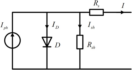
Figure 1. Equivalent circuit diagram of photovoltaic cells.
According to Figure 1, applying Kirchhoff’s current law, we can derive Equation 1:
where
According to the voltage-current relationship, the mathematical expression can be derived as Equation 2:
where
The three parameters
In practical scenarios,
This term can generally be neglected in practical applications.
In general,
where
where
To fully harness the power of photovoltaic (PV) systems, it is essential to achieve the Maximum Power Point (MPP). As solar irradiance varies, maximizing PV system efficiency requires studying MPPT methods. The equivalent circuit of a solar cell is a typical nonlinear circuit where the load voltage and current at the MPP change with irradiance variations. To consistently obtain maximum output power from the load, MPPT techniques are employed (Yan et al., 2018). Commonly used MPPT control methods in engineering include constant voltage tracking, perturb and observe method, and incremental conductance method.
This paper adopts the most commonly used perturb and observe method, whose specific process is illustrated in Figure 2.
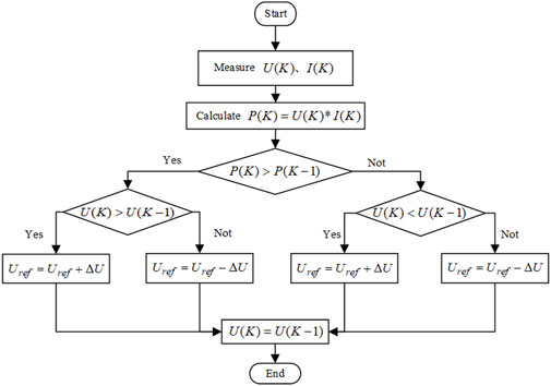
Figure 2. Flow diagram of perturbation observation method.
The principle of the perturb and observe method involves initially selecting a random point
2.2 Battery and bidirectional DC/DC converter
There are various circuit models for batteries, including the Rint model, Thevenin first-order model, and the PNGV (Partnership for a New Generation of Vehicles) second-order model, etc. (He et al., 2011). The equivalent circuits are shown in Figure 3.
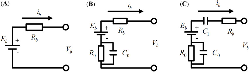
Figure 3. Battery equivalence model. (A) Rint model; (B) Thevenin model; (C) PNGV model.
The Rint model is a fundamental model for batteries and serves as a generic model for various types of batteries. Therefore, this paper adopts the Rint model for battery modeling. Based on Figure 3, we can get Equation 13:
The expression for the battery during the charging and discharging process is given by Equation 14:
where
In order to facilitate bidirectional energy flow, a bidirectional DC/DC converter is essential for the battery. Presently, four primary topologies exist for non-isolated bidirectional DC/DC converters, namely,: bidirectional Buck/Boost, bidirectional half-bridge, bidirectional Cuk, and bidirectional Sepic. After evaluating the distinct features of these topologies, this paper opts for the bidirectional half-bridge DC/DC converter as the battery’s charging and discharging converter. This choice is attributed to its notable advantages, including high efficiency, reduced voltage and current stress on the switches, and minimal conduction losses. Consequently, the bidirectional half-bridge DC/DC converter is adopted in this study for battery charge/discharge management.
In the bidirectional half-bridge DC/DC circuit, there are two switches, S1 and S2. By controlling these two switches, the battery can be charged and discharged. The drive signals for the two switches can either be complementary or independently control each switch.
In this paper, the switches S1 and S2 are controlled independently. To achieve rapid switching between charging and discharging of the battery, a dual-loop voltage and current control strategy is employed for the energy storage DC/DC converter to achieve voltage regulation. Both the voltage loop and the current loop are regulated by PI controllers. The outer voltage loop ensures stable control of the DC bus voltage, while the inner current loop regulates the inductor current.
In summary, the operational structure of the photovoltaic energy storage system discussed in this paper is shown in Figure 4.
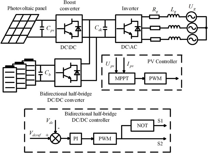
Figure 4. Diagram of the operation structure of the optical storage system.
3 Traditional VSG control method
Virtual Synchronous Generator introduces the electromechanical transient characteristics of a synchronous generator, such as rotational inertia and damping, to enable the inverter to have active frequency regulation and reactive voltage regulation capabilities. The control structure block diagram is shown in Figure 5.
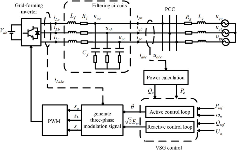
Figure 5. VSG grid-tied system topology.
In the main circuit topology of Figure 5,
3.1 Active power-frequency control
The VSG active power-frequency control can provide inertia support and primary frequency regulation characteristics for the system. Based on the second-order model of the SG, the VSG active power-frequency control equation can be derived as shown in Equation 17:
where
Based on Equation 17, the VSG active power-frequency control structure is illustrated in Figure 6.
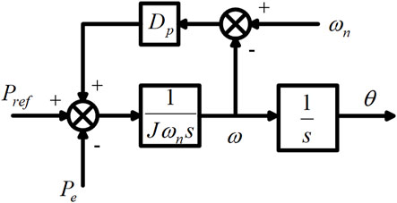
Figure 6. VSG active -frequency control structure.
3.2 Reactive power-voltage control
The VSG reactive power-voltage control simulates the primary voltage regulation characteristics of a synchronous generator (SG). Its mathematical expression is given by Equation 18:
where
Based on Equation 18, the VSG reactive power-voltage control structure is depicted in Figure 7.
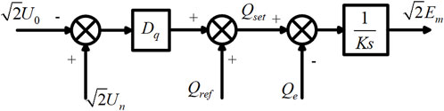
Figure 7. VSG reactive-voltage control structure.
The output of the VSG reactive power-voltage loop is the peak amplitude of the three-phase modulation waveform
The generated modulation waveforms are subjected to PWM (Pulse Width Modulation) to obtain the drive signals for the grid-connected inverter, thereby controlling the system.
4 Adaptive inertia control strategy based on improved active power-frequency loop
4.1 Adaptive inertia control for VSG
VSG provides effective damping for system disturbances, but traditional VSG with fixed inertia lacks robust dynamic adjustment capabilities to swiftly respond to changes in system power and frequency. If the value of
The VSG rotor angle and frequency oscillation curves are depicted in Figures 8, 9 respectively, where scenarios ①, ②, ③, and ④ correspond to moments
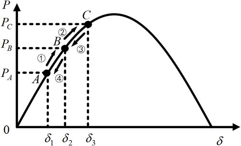
Figure 8. VSG power angle curve.

Figure 9. VSG rotor angular frequency oscillation curve.
Based on the above curves, the system’s dynamic adjustment process can be divided into four stages (Shi et al., 2023):
Stage ①: When the system active power reference exceeds the output value, power increases from
Stage ②: At point B, the VSG reaches a brief equilibrium where the angular acceleration is 0. However, the angular frequency
Stage ③: At point C, the VSG briefly reaches equilibrium. However, at this moment, the system’s active power reference is less than the output value. To prevent angular frequency deviation, the rotational inertia
Stage ④: At time
The oscillation continues in this manner until the angular frequency deviation reaches zero, and the system returns to stability. The demand for rotational inertia
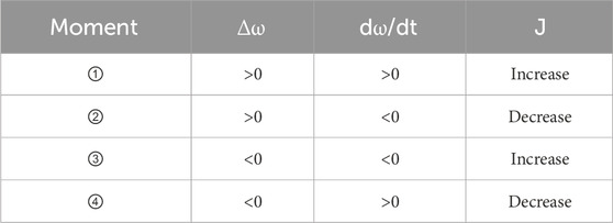
Table 1. The requirement for moment of inertia during VSG oscillation.
Based on Table 1, an adaptive virtual inertia algorithm is proposed and designed as Equation 20:
where
Therefore, the constant moment of inertia

Figure 10. VSG adaptive inertia control structure.
4.2 Improved active power-frequency loop
For the traditional VSG control, the introduction of virtual inertia in the active power-frequency control loop provides inertia support to the system, but also increases the possibility of system oscillations and may result in larger overshoots (Yang et al., 2023). Therefore, this paper emends transient damping power compensation control within the VSG active power loop, and thereby proposes an improved active power-frequency loop (Wang et al., 2022). The proposed active power-frequency loop can suppress oscillations in active power and frequency fluctuations generated during system power and frequency fluctuations. The specific control structure is illustrated in Figure 11.
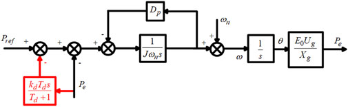
Figure 11. Improved active-frequency control of VSG.
In Figure 11,
According to Figure 11, the closed-loop transfer function of the improved active power-frequency loop is derived as Equation 21:
where
The closed-loop transfer function expression of the traditional VSG active power-frequency loop can be obtained as Equation 22:
Perform Bode plot analysis of the closed-loop transfer functions before and after improvement in the active power-frequency loop, as illustrated in Figure 12.
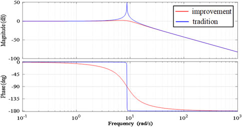
Figure 12. Closed-loop transfer function bode plot of active-frequency loop before and after improvement.
From Figure 12, it can be noted that in terms of amplitude response, the traditional control strategy exhibits oscillatory behavior, whereas the improved control strategy eliminates oscillations, resulting in smoother curves and enhanced system stability. Regarding phase response, the improved control strategy shows smoother phase transitions. Compared to the traditional control strategy, the phase descent near the cutoff frequency is more gradual, indicating a wider stable phase margin and improved system robustness. Overall, the improved control strategy enhances the system’s disturbance rejection capability and improves dynamic response performance.
4.3 Proposed VSG control method
According to the above analysis, the traditional VSG control adopts a fixed inertia and cannot provide effective damping. Besides, the introduction of virtual inertia in the active power-frequency control loop also increases the possibility of the system oscillation and overshoot and reduces the system stability. In order to simultaneously solve these two issues, an adaptive inertia control strategy based on the improved active power-frequency loop is proposed in this paper, which combines the adaptive inertia control method for VSG and the improved active-frequency loop.
Therefore, combining Figures 10, 11, the adaptive inertia control structure of VSG based on the improved active power-frequency loop is designed, shown as Figure 13. The proposed strategy can improve the system intermittency and variability issues by reducing system fluctuations and minimizing oscillatory overshoot and enhance system dynamic response performance and stability, providing inertia and damping characteristics similar to synchronous generators.
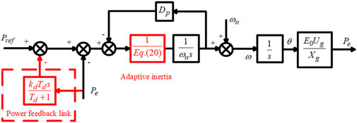
Figure 13. Adaptive inertia control based on an improved active-frequency loop.
5 Simulation results
To validate the proposed control strategy, a simulation model is constructed in MATLAB/Simulink. This study compares the output characteristics of traditional VSG control, adaptive inertia VSG control, and the proposed VSG control under various conditions such as frequency fluctuations, power reference step changes, and double fluctuation of photovoltaic frequency to assess their performance across different operating scenarios. The main parameters of the simulation model are listed in Table 2.
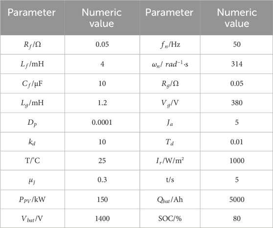
Table 2. Main circuit and control circuit parameters.
5.1 Simulation verification of system frequency fluctuation
To study the performance of VSG during system frequency fluctuations, we consider the operation of VSG output power under varying system frequencies. The simulation duration is 6 s with initial active and reactive power setpoints of 150 kW and 0 Var, respectively, and an initial illumination intensity of 1000 W/m2. At 2 s, the system frequency changes from 50 Hz to 49.9 Hz, returning to 50 Hz at 4 s. The system frequency response waveform is shown in Supplementary Figure S1. The active power output of VSG under different control strategies is shown in Supplementary Figure S2. Under the proposed control method, the VSG output power is illustrated in Supplementary Figure S3, the DC bus voltage in Supplementary Figure S4, and the output powers of each module in Supplementary Figure S5.
From Supplementary Figure S1, it can be observed that frequency fluctuations affect the output of VSG, and all three control strategies exhibit characteristics similar to primary frequency regulation in traditional generators. Compared to the other two controls, the proposed strategy shows smaller fluctuations in output power, achieves power setpoints quickly, and maintains smoother operation.
From Supplementary Figures S2, S3, it can be observed that the proposed strategy exhibits primary frequency regulation characteristics, effectively increasing power output to counter frequency deficits. The DC bus voltage shows minimal fluctuation during system frequency variations, quickly returning to stability, highlighting the proposed method’s advantage in transient system stability.
From Supplementary Figure S4, it can be seen that when the system frequency decreases, VSG modules emulate the primary frequency regulation characteristic of synchronous generators by increasing power generation. However, since the illumination intensity remains unchanged during this time, the output from the photovoltaic modules remains constant. The additional power generated by VSG is supplied by the energy storage modules, with the energy storage batteries being in a discharge state.
5.2 Simulation verification of power reference step
To study the transient behavior of VSG, we consider the operation when the VSG power setpoint undergoes a step change. At 3 s, the given active power setpoint increases from 150 kW to 250 kW, while other settings remain the same as described earlier. The active power output of VSG under different control strategies is shown in Supplementary Figure S5. Under the proposed control method, the output powers of each module are depicted in Supplementary Figure S6.
From Supplementary Figure S5, it can be clearly observed that when the power reference undergoes a step change from 150 kW to 250 kW at 3 s, the proposed control strategy enables the PV-storage system to quickly reach the new active power setpoint. Compared to the traditional VSG control and the adaptive inertia VSG control, the proposed method shows significantly smaller power fluctuations and faster transient response, demonstrating its effectiveness in reducing system overshoot and enhancing dynamic performance. From Supplementary Figure S6, it can be clearly observed that when the system active power reference value increases, the additional power generated by the VSG is provided by the energy storage module, and the energy storage battery is in a discharged state.
5.3 Simulation verification of double fluctuation of photovoltaic frequency
To study the overall performance of the solar energy storage system under combined fluctuations of irradiance and frequency, we consider the system power output when both irradiance and frequency fluctuate simultaneously. At 2 s, the system frequency decreases by 0.1 Hz, and irradiance drops by 200 W/m2. At 4 s, the system frequency returns to 50 Hz, and irradiance increases by 400 W/m2. All other settings remain the same as described earlier. Under the proposed control method, the output powers of each module are shown in Supplementary Figure S7.
From Supplementary Figure S7, it can be observed that when the system frequency decreases, VSG modules emulate the primary frequency regulation characteristic of synchronous generators by increasing power generation. However, due to a decrease in irradiance by 200 W/m2, the system experiences an active power deficit consisting of the reduced output from the photovoltaic modules plus the additional active power generated by VSG modules for primary frequency regulation. These deficits are compensated by the energy storage modules, leading to a significant increase in output power from the energy storage batteries, which discharge during this period. When the system frequency returns to normal, the additional power generation by VSG ceases, maintaining steady-state operation. However, with an increase in irradiance by 400 W/m2, the output from the photovoltaic modules increases, resulting in an excess of active power in the system. This surplus power is stored by the energy storage modules, leading to the energy storage batteries being in a charging state.
In summary, the proposed method efficiently integrates renewable energy sources, reducing the variability of photovoltaic generation. By dynamically adjusting the inertia parameter based on real-time system conditions, the method ensures that the PV-storage system can respond swiftly and effectively to changes in grid frequency and load demand. This adaptive control strategy not only enhances the stability of the PV-storage system but also improves its dynamic response performance, making it a promising solution for the grid integration of renewable energy.
6 Conclusion
This paper integrates the solar energy storage system with VSG and proposes an adaptive inertia control method based on improved active power regulation. Compared to traditional control methods, the proposed approach addresses the intermittency and variability issues of photovoltaic (PV) systems by reducing system fluctuations and minimizing oscillatory overshoot. It enhances system dynamic response performance and stability, providing inertia and damping characteristics similar to synchronous generators. This enables participation in grid frequency and voltage regulation, thereby improving the grid integration of renewable energy generation.
Data availability statement
The raw data supporting the conclusion of this article will be made available by the authors, without undue reservation.
Author contributions
YZ: Methodology, Writing–review and editing. YX: Investigation, Methodology, Writing–original draft. YeY: Investigation, Software, Writing–original draft, LH: Investigation, Writing–original draft. YuY: Writing–original draft.
Funding
The author(s) declare that financial support was received for the research, authorship, and/or publication of this article. This work was financially supported by the Science and Technology Support Program of Electric Power Scientific Research Institute of Guizhou Power Grid Co., Ltd. and China Southern Power Grid Co., Ltd. (GZKJXM20222419). The funder was not involved in the study design, collection, analysis, interpretation of data, the writing of this article, or the decision to submit it for publication.
Conflict of interest
Authors YZ, YX, YeY, LH, and YuY were employed by Electric Power Research Institute of Guizhou Power Grid Co., Ltd.
Publisher’s note
All claims expressed in this article are solely those of the authors and do not necessarily represent those of their affiliated organizations, or those of the publisher, the editors and the reviewers. Any product that may be evaluated in this article, or claim that may be made by its manufacturer, is not guaranteed or endorsed by the publisher.
Supplementary material
The Supplementary Material for this article can be found online at: https://www.frontiersin.org/articles/10.3389/fenrg.2024.1468629/full#supplementary-material
References
Chen, Q., Zhu, B., Liu, M., and Mao, S. (2024). Analysis of grid-connected stability of VSG-controlled PV plant integrated with energy storage system and optimization of control parameters. Electronics 13 (7), 1343. doi:10.3390/electronics13071343
Grover, H., Sharma, S., Verma, A., Hossain, M. J., and Kamwa, I. (2024). Adaptive parameter tuning strategy of VSG-based islanded microgrid under uncertainties. Electric Power Systems Research 235, 110854. doi:10.1016/j.epsr.2024.110854
Hasabelrasul, H., Cai, Z., Sun, L., Suo, X., and Matraji, I. (2022). Two-stage converter standalone PV-battery system based on VSG control. IEEE Access 10, 39825–39832. doi:10.1109/access.2022.3165664
He, H., Xiong, R., and Fan, J. (2011). Evaluation of lithium-ion battery equivalent circuit models for state of charge estimation by an experimental approach. Energies 4 (4), 582–598. doi:10.3390/en4040582
Hua, T., Yan, X., and Fan, W. (2017). “Research on power point tracking algorithm considered spinning reserve capacity in gird-connected photovoltaic system based on VSG control strategy,” in 2017 IEEE 3rd international future energy electronics Conference and ECCE Asia (IFEEC 2017-ECCE Asia: IEEE), 2059–2063.
Jiang, L., and Chen, X. (2023). “An adaptive power control of photovoltaic virtual synchronous generators,” in 2023 6th International Conference on Power and energy applications (ICPEA: IEEE), 27–32.
Li, C., and Yuan, S. (2021). Research on frequency modulation control of photovoltaic power generation system based on VSG. International Journal of Low-Carbon Technol. 16 (2), 287–293. doi:10.1093/ijlct/ctaa054
Liang, J., Fan, H., Cheng, L., Rong, S., Li, T., Yu, T., et al. (2024). Control strategy for improving the frequency response characteristics of photovoltaic and energy storage systems based on VSG control. Energy Rep. 11, 2295–2305. doi:10.1016/j.egyr.2024.01.036
Liu, J., Hou, Y., Guo, J., Liu, X., and Liu, J. (2023). A cost-efficient virtual synchronous generator system based on coordinated photovoltaic and supercapacitor. IEEE Trans. Power Electron. 38, 16219–16229. doi:10.1109/TPEL.2023.3317497
Liu, Y., Wang, Y., Wang, M., Xu, Z., Peng, Y., and Li, M. (2022). Coordinated VSG control of photovoltaic/battery system for maximum power output and grid supporting. IEEE Journal Emerg. Sel. Top. Circuits Systems 12 (1), 301–309. doi:10.1109/JETCAS.2022.3143716
Mao, M., Qian, C., and Ding, Y. (2018). Decentralized coordination power control for islanding microgrid based on PV/BES-VSG. CPSS Trans. Power Electron. Appl. 3 (1), 14–24. doi:10.24295/CPSSTPEA.2018.00002
Meng, J., Sun, Y., Wang, Y., Zhao, P., Liu, B., and Wang, K. (2022). Cooperative adaptive inertial control for PV and energy storage units with multiple constraints. IET Renew. Power Gener. 16 (10), 2076–2087. doi:10.1049/rpg2.12488
Mohamed, M. M., El Zoghby, H. M., Sharaf, S. M., and Mosa, M. A. (2022). Optimal virtual synchronous generator control of battery/supercapacitor hybrid energy storage system for frequency response enhancement of photovoltaic/diesel microgrid. Journal of Energy Storage 51, 104317. doi:10.1016/j.est.2022.104317
Qiu, T., Gong, Z., Zhang, H., Li, J., Wang, J., Wu, Q., et al. (2023). A multi-objective optimization model of an integrated electric and thermal energy system considering the consumption of renewable energy. Power big data 26 (5), 18–24. doi:10.19317/j.cnki.1008-083x.2023.05.003
Quan, X., Yu, R., Zhao, X., Lei, Y., Chen, T., Li, C., et al. (2019). Photovoltaic synchronous generator: architecture and control strategy for a grid-forming PV energy system. IEEE Journal of Emerg. Sel. Top. Power Electron. 8 (2), 936–948. doi:10.1109/JESTPE.2019.2953178
Shi, T., Sun, J., Han, X., and Tang, C. (2023). Research on adaptive optimal control strategy of virtual synchronous generator inertia and damping parameters. IET Power Electron. 17 (1), 121–133. doi:10.1049/pel2.12620
Tahir, W., Farhan, M., Bhatti, A. R., Butt, A. D., and Farid, G. (2024). A modified control strategy for seamless switching of virtual synchronous generator-based inverter using frequency, phase, and voltage regulation. International Journal of Electr. Power and Energy Systems 157, 109805. doi:10.1016/j.ijepes.2024.109805
Wang, Z., Chen, Y., Li, X., Xu, Y., Luo, C., Li, Q., et al. (2022). Active power oscillation suppression based on decentralized transient damping control for parallel virtual synchronous generators. IEEE Trans. Smart Grid 14 (4), 2582–2592. doi:10.1109/TSG.2022.3233121
Yan, X., Li, J., Wang, L., Zhao, S., Li, T., Lv, Z., et al. (2018). Adaptive-MPPT-based control of improved photovoltaic virtual synchronous generators. Energies 11 (7), 1834. doi:10.3390/en11071834
Yan, X., Wang, C., Wang, Z., Ma, H., Liang, B., and Wei, X. (2021). A united control strategy of photovoltaic-battery energy storage system based on voltage-frequency controlled VSG. Electronics 10 (17), 2047. doi:10.3390/electronics10172047
Yang, M., Wang, Y., Chen, S., Xiao, X., and Li, Y. (2023). Comparative studies on damping control strategies for virtual synchronous generators. IEEE Trans. Power Deliv. 39, 859–873. doi:10.1109/TPWRD.2023.3339288
Yao, J., Zhang, X., Song, J., and Dong, X. (2023). Short-term load forecasting of power systems that take into account the integration of PV and wind power into the grid. Power big data 26 (7), 10–22. doi:10.19317/j.cnki.1008-083x.2023.07.002
Yu, G., Xu, J., Wu, G., Zhang, Z., and Zhao, D. (2023). Improved virtual synchronous generator control strategy for the flexible interconnection system in distribution transformer areas. Electric Power Systems Research 214, 108877. doi:10.1016/j.epsr.2022.108877
Zhang, B., Zhang, X., Yang, E., and Yan, X. (2022a). Economic analysis and configuration design for the energy storage unit of photovoltaic virtual synchronous generator based on the inertia support and primary frequency control. International Journal of Electr. Power and Energy Systems 134, 107349. doi:10.1016/j.ijepes.2021.107349
Zhang, B., Zhao, P., and Zhao, J. (2022b). Research on control strategy of two-stage photovoltaic virtual synchronous generator with variable power point tracking. Energy Rep. 8, 283–290. doi:10.1016/j.egyr.2021.11.191
Zhang, X., Hu, Y., Mao, W., Zhao, T., Wang, M., Liu, F., et al. (2020). A grid-supporting strategy for cascaded H-bridge PV converter using VSG algorithm with modular active power reserve. IEEE Trans. Industrial Electron. 68 (1), 186–197. doi:10.1109/TIE.2019.2962492
Zhong, C., Zhou, Y., Chen, J., and Liu, Z. (2022). DC-side synchronous active power control of two-stage photovoltaic generation for frequency support in Islanded microgrids. Energy Rep. 8, 8361–8371. doi:10.1016/j.egyr.2022.06.030
Keywords: combined PV-storage system, grid-forming inverter, VSG, adaptive inertia, active power loop
Citation: Zheng Y, Xu Y, Yang Y, Hua L and Yang Y (2025) Application of adaptive virtual synchronous generator based on improved active power loop in photovoltaic storage systems. Front. Energy Res. 12:1468629. doi: 10.3389/fenrg.2024.1468629
Received: 22 July 2024; Accepted: 30 December 2024;
Published: 17 January 2025.
Edited by:
Minh Quan Duong, University of Science and Technology, The University of Danang, VietnamReviewed by:
Huy Nguyen Duc, Hanoi University of Science and Technology, VietnamNgo Minh Khoa, Quy Nhon University, Vietnam
Copyright © 2025 Zheng, Xu, Yang, Hua and Yang. This is an open-access article distributed under the terms of the Creative Commons Attribution License (CC BY). The use, distribution or reproduction in other forums is permitted, provided the original author(s) and the copyright owner(s) are credited and that the original publication in this journal is cited, in accordance with accepted academic practice. No use, distribution or reproduction is permitted which does not comply with these terms.
*Correspondence: Youzhuo Zheng, Mjk3NTI5NTY5MEBxcS5jb20=